modelling_the_wireless_propagation_channel_a
Autodesk Nastran 2023 参考手册说明书
FILESPEC ............................................................................................................................................................ 13
DISPFILE ............................................................................................................................................................. 11
File Management Directives – Output File Specifications: .............................................................................. 5
BULKDATAFILE .................................................................................................................................................... 7
simulink中model reference的用法 -回复
simulink中model reference的用法-回复Simulink中的Model Reference是一个非常强大且常用的功能,它允许用户在一个模型中嵌入另一个模型,从而使得系统的设计和开发更加模块化、可维护和可扩展。
在本文中,我们将逐步介绍Simulink中Model Reference的用法,并提供实例来帮助读者更好地理解。
Model Reference的概念和作用Model Reference是指在一个主模型中嵌入一个或多个子模型的设计方法。
在Simulink中,主模型通常被称为父模型或顶层模型,子模型则是在顶层模型中使用的模块化组件。
Model Reference的好处主要有以下几个方面:1. 模块化开发:通过使用Model Reference,用户可以将复杂系统分解为更小、更易于管理的模块,使得系统的开发和维护变得更加简单和高效。
2. 可重用性:子模型可以重复使用,减少系统设计中的重复劳动,并提高代码的可维护性和可扩展性。
3. 团队协作:不同的团队成员可以独立开发和测试不同的子模型,从而提高团队的并行开发能力和协同工作效率。
Model Reference的使用步骤下面将介绍在Simulink中使用Model Reference的具体步骤。
步骤一:创建子模型在使用Model Reference之前,首先需要创建子模型。
可以将子模型定义为独立的模型文件,也可以在主模型中创建子系统,并将其转换为子模型。
子模型可以包含各种Simulink模块和功能,例如信号处理算法、控制逻辑和状态机等。
确保子模型在单独的命名空间中工作,以避免可能的变量名称冲突。
步骤二:在主模型中添加Model Reference Block一旦子模型创建完成,下一步是在主模型中添加Model Reference Block。
这可以通过在Simulink库浏览器中找到Model Reference Block,然后将其拖放到主模型中完成。
ASAAC通用功能模块规范

Ministry of DefenceInterim Defence Standard 00-76 Issue 1 Publication Date 14 January 2005ASAAC StandardsPart 1Proposed Standards for CommonFunctional ModulesNOTEThis standard is ProvisionalIf you have Difficulty with itsApplicationPlease Advise UK DefenceStandardizationAMENDMENT RECORDAmd No Date Text Affected Signature and DateREVISION NOTEHISTORICAL RECORDDefenceM R C. S IMS TANDARDS P ROGRAMME M ANAGER 2Procurement AgencyD/DStan/21/76/1UK Defence StandardizationRm 1138Kentigern House65 Brown StreetGlasgow G2 8EXDirect line:0141 224 2585Switchboard:0141 224 2531Facsimile:0141 224 2503e-mail:pdgsts1@14 December 2004INTERIM DEFENCE STANDARD - INVITATION TO COMMENTDefence Standard Number: 00-76 Part 1 Issue 1 INTERIMTitle: Standards for Common Functional ModulesThe above Defence Standard has been published as an INTERIM Standard and is provisional because it has not been agreed by all authorities concerned with its use. It shall be applied to obtain information and experience on its application which will then permit the submission of observations and comments from users.The purpose of this form therefore is to solicit any beneficial and constructive comment that will assist the author and/or working group to review the INTERIM Standard prior to it being converted to a normal Standard.Comments are to be entered below and any additional pertinent data which may also be of use in improving the Standard should be attached to this form and returned to writer at the above address.No acknowledgement to comments received will normally be issued.NAME: Calum Sim SIGNATURE: Calum Sim BRANCH: STAN OPS SPM 21. Does any part of the Standard create problems or require interpretation:YES NO If “yes” state under section 3:a. the clause number(s) and wording;b. the recommendation for correcting the deficiencies.2. Is the Defence Standard restrictive:YES NO If “yes” state in what way under section 3.AN EXECUTIVE AGENCY OF THE MINISTRY OF DEFENCE3. Comments, general or any requirement considered too rigid:Page Clause Comments Proposed Solution4. I/We agree that this Draft Standard, subject to my/our comments being taken into consideration, when published in final form will cover my/our requirements in full. Should you find my/our comments at variance with the majority, I/we shall be glad of the opportunity to enlarge upon them before final publication. Signature.................................................................Representing.................................................Submitted by (print or type name and address)Telephone number:Date:Our Ref:DSTAN Form 42INTERIM DEF STAN 00-76 PART 1Contents0Introduction (5)0.1Purpose (5)0.2Document structure (5)1Scope (7)1.1Relationship with other ASAAC Standards (7)2WARNING (7)3Normative references (8)4Terms, definitions and abbreviations (9)4.1Terms and definitions (9)4.2Abbreviations (9)4.3Conventions used in this Standard (11)4.3.1Special Fonts (11)4.3.2Naming Conventions (11)5CFM Definition (12)5.1Generic CFM (12)5.1.1Generic CFM – Description (12)5.1.2Generic CFM – Requirements (14)5.2Module Support Unit (15)5.2.1Module Support Unit – Description (15)5.2.2Module Support Unit – Requirements (15)5.2.3Module Support Layer (18)5.2.4Module Initialisation (19)5.3Module Processing Capability (22)5.3.1Data Processing Module (DPM) (24)5.3.2Signal Processing Module (SPM) (24)5.3.3Graphic Processing Module (GPM) (25)5.3.4Mass Memory Module (MMM) (26)5.3.5Power Conversion Module (PCM) (27)5.3.6Network Support Module (NSM) (29)5.4Network Interface Unit (NIU) and Routing Unit (RU) (30)5.4.1NIU and RU Description (30)5.4.2NIU and RU Requirements (31)5.5Module Power Supply Element (31)5.5.1Module Power Supply Element Description (31)5.5.2Module Power Supply Requirements (32)5.6Module Physical Interface (MPI) (32)5.6.1MPI Description (32)5.6.2MPI Requirements (32)6Common Functional Module Interfaces (32)6.1Module Logical Interface (MLI) (32)6.1.1MLI Description (32)6.1.2MLI Requirements (33)6.2Module Physical Interface (MPI) (33)6.2.1MPI Description (33)6.2.2MPI Requirement (33)6.3MOS Interface (33)6.3.1MOS Interface Description (33)6.3.2MOS Interface – Requirement (34)7CFM System Support and Guidelines (34)7.1Fault Management (34)7.2Fault Detection (34)7.3Fault Masking (34)7.4Fault Confinement (35)7.5Safety and Security (35)7.5.1Safety35iiiINTERIM DEF STAN 00-76 PART 17.5.2Security (35)A.1.Data Processor Module (37)A.2.Signal Processing Module (38)A.3.Graphic Processing Module (39)A.4.Mass Memory Module (40)work Support Module (40)A.6.Power Conversion Module (41)FiguresFigure 1 - ASAAC Standard Documentation Hierarchy (5)Figure 2 - Functional representation of a generic CFM (14)Figure 3 - IMA Common Functional Modules – Graphical Composition (24)Figure 4 - The Power Supply Distribution functions of the PCM (29)Figure 5 - Power Supply Element functions (32)Figure 6 - Software Architecture Model - Three Layer Stack (35)TablesTable 1 - CFM Embedded Information - Read Only (16)Table 2 - CFM Embedded Information - Read / Write (18)Table 3 - PCM output characteristics (30)Table 4 - PSE input voltage characteristics (33)Table A-1 - Performance sheet for a DPM (39)Table A-2 - Performance sheet for a SPM (40)Table A-3 - Performance sheet for a GPM (41)Table A-4 - Performance sheet for a MMM (42)Table A-5 - Performance sheet for a NSM (42)Table A-6 - Performance sheet for a PCM (43)ivINTERIM DEF STAN 00-76 PART 11Introduction 0.1 PurposeThis document is produced under contract ASAAC Phase II Contract n°97/86.028.The purpose of the ASAAC Programme is to define and validate a set of open architecture standards,concepts and guidelines for Advanced Avionics Architectures (A3) in order to meet the three main ASAAC drivers. The standards, concepts and guidelines produced by the Programme are to be applicable to both new aircraft and update programmes from 2005.The three main goals for the ASAAC Programme are:1. Reduced life cycle costs.2. Improved mission performance.3. Improved operational performance.The ASAAC standards are organised as a set of documents including:- A set of agreed standards that describe, using a top down approach, the Architecture overview to allinterfaces required to implement the core within avionics system.-The guidelines for system implementation through application of the standards.The document hierarchy is given hereafter: (in this figure the document is highlighted)Figure 1 - ASAAC Standard Documentation HierarchyINTERIM DEF STAN 00-76 PART 120.2 Document structureThe document contains the following sections:-Section 1, scope of the document.-Section 2, normative references.-Section 4, the terms, definitions and abbreviations.-Sections 5 and 6 provide CFM concept definition, requirements and standards.-Section 7 provides guidelines for implementation of standards.- Performance sheets for each of the CFMs are attached to the end of the document. These sheetscontain a list of attributes to be defined by the system designer and used by the CFM provider.INTERIM DEF STAN 00-76 PART 131 ScopeThis standard defines the functionality and principle interfaces for the Common Functional Module (CFM) to ensure the interoperability of Common Functional Modules and provides design guidelines to assist in implementation of such a CFM. It is one of a set of standards that define an ASAAC (Allied Standard Avionics Architecture Council) Integrated Modular Avionics System.This definition of interfaces and functionality allows a CFM design that is interoperable with all other CFM to this standard, that is technology transparent, that is open to a multi-vendor market and that can make the best use of COTS technologies.Although the physical organisation and implementation of a CFM should remain the manufacturer’s choice,in accordance with the best use of the current technology, it is necessary to define a structure for each CFM in order to achieve a logical definition of the CFM with a defined functionality. This definition includes:- The Generic CFM, which defines the generic functionality applicable to the complete set of CFMs. Thegeneric functionality is defined in section 5.1.- The processing capability, which defines the unique functionality associated with each CFM type within the set. This functionality is defined in section 5.3.- The logical and physical interfaces that enable CFMs to be interoperable and interchangeable, these are defined in section 6.-The functionality required by a CFM to support the operation of the System is defined in section 7.1.1 Relationship with other ASAAC StandardsThe definition of the complete CFM is partitioned and is covered by the following ASAAC standards:-CFM Mechanical properties and physical Interfaces – ASAAC Standards for Packaging.-CFM Communication functions – ASAAC Standards for Software.-CFM Network interface – ASAAC Standards for Communications and Network.-CFM Software architecture – ASAAC Standards for Software.- CFM Functional requirements – This document.2 WARNINGThe Ministry of Defence (MOD), like its contractors, is subject to both United Kingdom and European laws regarding Health and Safety at Work, without exemption. All Defence Standards either directly or indirectly invoke the use of processes and procedures that could be injurious to health if adequate precautions are not taken. Defence Standards or their use in no way absolves users from complying with statutory and legal requirements relating to Health and Safety at Work.INTERIM DEF STAN 00-76 PART 13 Normative references3.1The publications shown below are referred to in the text of this Standard. Publications are grouped and listed in alphanumeric order.This European Standard incorporates by dated or undated reference, provisions from other publications. These normative references are cited at the appropriate places in the text and the publications are listed hereafter. For dated references, subsequent amendments to or revisions of any of these publications apply to this European Standard only when incorporated in it by amendment or revision. For updated references the latest edition of the publication referred to applies (including amendments).A) References to published standards[1] ISO/CD 1540Aerospace - Characteristics of aircraft electricalsystems - ISO/TC20/SC 1/WG 13 - Date: 20/04/1998B) References to standards in preparation[2] ASAAC2-STA-32410-001-SWG Issue 01Final Draft of Proposed Standards for Software1[3] ASAAC2-STA-32420-001-HWG Issue 01Final Draft of Proposed Standards forCommunications/Network1[4] ASAAC2-STA-32440-001-HWG Issue 01Final Draft of Proposed Standards for Packaging1[5] ASAAC2-GUI-32450-001-CPG Issue 01Final Draft of Proposed Guidelines for System Issues –Volume 2: Fault Management1[6] ASAAC2-STA-32460-001-CPG Issue 01Final Draft of Proposed Standards for Architecture1C) References to other documents[7] The Common Object Request Broker Architecture and Specification, Issue 2.3, OMG2[8] ASAAC2-GUI-32450-001-CPG Issue 01Final Draft of Proposed Guidelines for System Issues –Volume 5: Time ManagementD) References to documents from other organisations[9] IEEE Std JTAG 1149.1 Boundary Scan33.2Reference in this Standard to any related document means in any Invitation to Tender or contract the edition and all amendments current at the date of such tender or contract unless a specific edition is indicated.3.3In consideration of clause 3.2 above, users shall be fully aware of the issue and amendment status of all related documents, particularly when forming part of an Invitation to Tender or contract. Responsibility for the correct application of standards rests with users.3.4DStan can advise regarding where related documents are obtained from. Requests for such information can be made to the DStan Helpdesk. How to contact the helpdesk is shown on the outside rear cover of Def Stans.1 Published by: Allied Standard Avionics Architecture Council2 Published by: Object Management Group3 Published by: IEEE44 Terms, definitions and abbreviations4.1 Terms and definitionsUse of “shall”, “should” and “may” within the standards observe the following rules:- The word SHALL in the text expresses a mandatory requirement of the standard.- The word SHOULD in the text expresses a recommendation or advice on implementing such a requirement of the standard. It is expected that such recommendations or advice will be followed unless good reasons are stated for not doing so.- The word MAY in the text expresses a permissible practice or action. It does not express a requirement of the standard.Open System: A system with characteristics that comply with specified, publicly maintained, readily available standards and that therefore can be connected to other systems that comply withthese same standards.4.2 Abbreviations2D Two Dimensional3D Three DimensionalA3Advanced Avionics ArchitectureAGT Absolute Global TimeALT Absolute Local TimeAPOS Application to Operating System InterfaceASAAC Allied Standard Avionics Architecture CouncilBIT Built-in TestCBIT Continuous BITCFM Common Functional ModuleCORBA Common Object Request Broker ArchitectureCOTS Commercial Off The ShelfCRC Cyclic Redundancy Checkdc Direct CurrentDPM Data Processing ModuleDSP Digital Signal ProcessorEDAC Error Detection And CorrectionFFT Fast Fouriert TransformationFIR Finite Impulse response FilterFMECA Fault Mode Effect and Criticality AnalysisGPM Graphic Processing ModuleGSM Generic System ManagementHW HardwareHDD Head-Down DisplayHMD Helmet Mounted DisplayHUD Head-Up DisplayIBIT Initiated BITID IdentificationIDL Interface Definition LanguageIEEE Institute of Electrical and Electronics Engineers IFFT Inverse Fast Fourier TransformationIMA Integrated Modular AvionicsISO International Standards OrganisationITM Integrated Test and MaintenanceJTAG Joint Test Action GroupMC Module ControllerMIS Module Initialisation SupportMLI Module Logical InterfaceMMM Mass Memory ModuleMOS Module Support Layer to Operating System Interface MPI Module Physical InterfaceMSL Module Support LayerMSU Module Support UnitMTP Maintenance Test PortN/A Not ApplicableNIU Network Interface UnitNSM Network Support ModuleOMG Object Management GroupO/P OutputOS Operating SystemOSL Operating System LayerPBIT Power-up / power-down BITPCM Power Conversion ModulePCU Power Conversion UnitPE Processing ElementPMS Power Management SystemPSA Power Switch ArrayPSE Power Supply ElementPU Processing UnitRC Reference ClockRLT Relative Local TimeRTBP Runtime BlueprintsRU Routing UnitSPM Signal Processing ModuleTC Transfer ConnectionTLS Three Layer StackVdc Voltage dc4.3 Conventions used in this StandardThe Interface Definition Language (IDL) as defined in the Common Object Request Broker Architecture (CORBA) 2.3 is used to express the MOS services as programming language independent services in this document. Fore more details refer to [7] .The conventions used in this document are as follows:4.3.1 Special FontsWords that have a special meaning appear in specific fonts or font styles. All code listings, reserved words and the name of actual data structures, constants, and routines are shown in Courier.4.3.2 Naming ConventionsParameter and variable names contain only words with lower case letters, which are separated by underscore.Example:vc_messageNOTE: Upper and lower case letters are treated as the same letter.5 CFM DefinitionThe Common Functional Modules (CFMs) are line replaceable items and provide an ASAAC IMA system with a computational capability, network support capability and power conversion capability. The following set of modules have been defined for use within an IMA core processing system:- Signal Processing Module (SPM).- Data Processing Module (DPM).- Graphics Processing Module (GPM).- Mass Memory Module (MMM).- Network Support Module (NSM).- Power Conversion Module (PCM).This set of CFMs complies with the generic CFM format defined in this section.It is assumed that a System Design Specification will be raised for each specific project implementation in which the detailed performance requirements for each CFM will appear.5.1 Generic CFM5.1.1 Generic CFM – DescriptionThe internal architecture of each CFM consists of a set of functional elements that are applied to each CFM implementation. These are shown graphically in Figure 2 and are detailed below. All functions, with the exception of the Processing Unit, are generic to each CFM type.PowerLinks to NetworkFigure 2 - Functional representation of a generic CFM(For PCM and NSM refer to Figure 3)- The Module Support Unit (MSU) controls and monitors the module and provides common functions such as Built-in-Test (BIT) control, module initialisation, time management, status recording/reporting and support for MLI (section 6), system management and debugging.- The Processing Unit (PU) provides the specific function of a CFM, for example data processing, signal processing, mass storage. These are defined in section 5.3.- The Module Physical Interface (MPI) defines the physical characteristics of the module and implements the mechanical, optical, electrical and cooling interfaces. These are detailed in section 6 and are fully defined in the ASAAC Standards for Packaging [4] .- The Routing Unit (RU) provides the internal communications capability of the CFM and interconnects the Network Interface Unit (NIU) with the Processing Unit (PU) and the Module Support Unit (MSU). The RU also provides a direct coupling between a network input link and a network output link. The RU iscontrolled by the MSU.- The Network Interface Unit (NIU) performs the external communications capability by interfacing the off-module network with the module internal data paths implemented by the Routing Unit. The NIU supports the implementation of the communication part and the Network properties part of the Module Logical Interface (MLI). These are defined in the ASAAC Software Standard [2] and the ASAAC Standards for Communications and Network [3] respectively. It also supports network configuration in conjunction with the MSU.- The Power Supply Element (PSE) converts the external supply voltage into the appropriate internal supply voltages. Consolidation of redundant multiple power inputs shall also be provided by the PSE.The power supply architecture is defined in the ASAAC Standards for Architecture [6] .The CFM shall comprise hardware components, that implement the mechanical and electrical functionality and the physical interfaces of the CFM and software components collectively termed the “Module Support Layer” (MSL). The MSL provides, in conjunction with the hardware, the functional requirements and logical interfaces defined in the ASAAC Standards identified in section 1.1.The interfaces for the CFM are as follows and are detailed in section 6:- The Module Physical Interface (MPI), which defines the physical properties of the CFM including the mechanical, optical, electrical and cooling interfaces.- The Module Logical Interface (MLI), which defines the logical communication and command interface of the CFM.- The interface between the Module Support Layer (MSL) and the Operating System, the MOS, which provides generic, technology independent access to the low-level resources of a CFM and thecommunications interface to the other CFMs.5.1.2 Generic CFM – RequirementsAll CFMs designed to this standard shall meet the following requirements:- Have all set of functional elements as shown in Figure 2 for DPM, SPM, MMM and GPM. For PCM and NSM refer to Figure 3.- Provide open system (see for definition 4.1) compliant processing hardware,- Promote insertion and use of commercial and military standards and technologies, and the reuse of software.- Provide integrated diagnostics (built-in test) and fault isolation means to support fault tolerance, failure management, reconfiguration and maintenance.- Conform to the Module Physical Interface (MPI) definition [4] and section 5.6.- Support at least one input and one output link to the network. The number of links will be dependent on the module type and system implementation.- Comply with the MOS interface definition and provide the required supporting software in the MSL. This software must also meet the requirements defined in the ASAAC Standards for Software [2] . The NSM is exempt from this requirement.- Provide the common communication services, within the MOS interface, to allow access to the network resources [2] .- Comply with the MLI definition. Note, that the NSM shall comply to the appropriate sub-set [2] .- Be programmable in high-level languages.- Time synchronisation, for more details see reference [8] . Note that the NSM and MMM have additional time distribution capability.- Ensure internal communication bandwidth is compatible with external communication.- Comply with the Power Supply Architecture Specified in the ASAAC Standards for Architecture [6] : - Provide the second stage of the power supply architecture.- Be capable of operating in a fault tolerant configuration, i.e. it shall be possible to consolidate power supplies of a CFM (with the exception of the PCM) from two or more PCMs.5.2 Module Support UnitThis section covers the generic functionality provided by the MSU.5.2.1 Module Support Unit – DescriptionThe module support functionality is to be provided by the logical element the MSU. The MSU controls and monitors all activities for a DPM, SPM, GPM and MMM. The MSU provides all functions and services required for system management, external and internal communications and module management. Guidelines for these functions are provided in the ASAAC Standards for Software [2] . In order to achieve the flexibility to control different types of modules a general-purpose processor called a Module Controller (MC) may be used.5.2.2 Module Support Unit – RequirementsThe services and capabilities, which shall be provided by the MSU, are described in the following sections.5.2.2.1 CFM Embedded InformationEach CFM shall contain information regarding particular characteristics of the CFM itself. This information shall be located in non-volatile storage to ensure no loss of information caused by removal of power.The information to be stored shall be distinguished as follows:- Read-Only is information that, after definition and programming, cannot be altered during operational use. The original manufacturer shall be the only one who is capable of programming or modifying these data. This constitutes data such as the manufacturers identity, CFM type, production batch number etc.that reflect the identity of the CFM. The required retrievable information are listed in Table 1.- Read/Write is information that can be updated whenever the module is operational. This constitutes data such as the hours of operation, executed maintenance activities, operational log, etc. that reflect the operational history of the CFM. The required information that shall be available is listed in Table 2. Fault Logging is considered separately in section 5.2.2.3.The information with read-only access shall be accessible using the following methods:- By interrogation of the Maintenance Test Port, a function covered in detail in section 5.2.2.6.- By use of the MOS services, defined in the Software Standard, reference [2] .Table 1 - CFM Embedded Information - Read OnlyName Definition Type Lengthin BytesScope Accessed Via manufacturer_id Manufacturer's ID String30Global moduleInfo/MTPserial_id Serial ID unsignedShort Specific to a singlemanufacturermoduleInfo/MTPprod_batch_ date Date of production (week:2year: 4)String6N/A MTPcfm_type Standard type of CFM (SPM,DPM, GPM, MMM, NSM, PCM)String10Global moduleInfo/MTPhw_version Version of hardware unsignedShort Specific to a single manufacturerMTPmsl_version Version of MSL code stored on-CFM unsignedShortSpecific to a singlemanufacturerMTPName Definition Type Lengthin BytesScope Accessed Viastandard_mpi_ version_ compliance Version of the MPI standard thatthe CFM is compatible withunsignedShortGlobal MTPstandard_mos_ve rsion_ compliance Version of the MOS standardthat the CFM is compatible withunsignedShortGlobal moduleInfo/MTPstandard_mli_ version_ compliance Version of the MLI standard thatthe CFM is compatible withunsignedShortGlobal moduleInfo/MTPnum_network Number of different networkinterfaces on the CFM unsignedShortSpecific to CFM moduleInfo/MTPnum_pe Number of PEs resident on theCFM unsignedShortSpecific to CFM moduleInfo/MTPFor each Network interface resident on the CFMnetwork_if_id Network interface ID unsignedShortSpecific to CFM moduleInfo/MTPnetwork_if_type Type of network interface(variable scope shall be acrossall possible network interfacetypes)String10Global moduleInfo/MTPFor each PE resident on the CFMpe_id PE ID unsignedShortSpecific to CFM moduleInfo/MTPpe_type Type of PE (variable scope shallbe across all possible PE types)String10Global moduleInfo/MTPpe_performance Standardised performanceavailable from PE in MOPS unsignedLongSpecific to PE moduleInfo/MTPpe_nonvol_ memory Amount of available non-volatilememory within each PE inMbytesunsignedLongSpecific to PE moduleInfo/MTPpe_vol_memory Amount of available volatilememory within each PE inMbytes unsignedLongSpecific to PE moduleInfo/MTPpe_num_timer Number of Timers within the PE unsignedShortSpecific to PE moduleInfo/MTP For each Timer within each PE resident on the CFMpe_timer_id Timer ID unsignedShortSpecific to PE moduleInfo/MTPpe_timer_ resolution Resolution of the timer innanosecondsunsignedShortSpecific to PETimerModuleInfo/MTPTable 2 - CFM Embedded Information - Read / WriteName Definition Type LengthIn BytesAccessed viaoperational_hou rs Number of operational hours for the CFM(resolution = 1 minute)unsigned Long moduleStatus/MTP: read onlymaintenance_log Log describing the maintenance history of theCFM. A log entry needs to include:Up to 256bytes perentryreadLogDevice:read onlyMTP: read/write•Time-stamp (op hours)•Maintainer identity •Maintenance action identity unsigned LongStringString30222system_log Log describing the usage history of the CFM.A log entry needs to include:32 bytesper entryreadLogDevice/MTP: read onlywriteLogDevice:write only•Time-stamp (op hours)•Relevant system identity unsigned LongString28cfm_status Present status of the CFM; OK, Fail, PBIT inprogress, IBIT in progress etc.String10moduleStatus/MTP: read only5.2.2.2 Built-in Test Capability (BIT)Each CFM shall provide hardware and software resources to provide a level of fault detection within its own resources according to the following three BIT capabilities:- Power-up/Power-down BIT (PBIT) - Performs built-in test subsequent to module power-up. PBIT shall verify that the resources available on the CFM are fully operational before operational code isdownloaded. Details on the initialisation are given in section 5.2.4.- Continuous BIT (CBIT) - CBIT shall be performed as a background activity during normal operation of the CFM.- Initiated BIT (IBIT) - IBIT shall be performed when initiated by another entity. After initiation of IBIT the normal operation of the CFM shall be interrupted and IBIT performed. After IBIT has terminated the CFM shall return to normal operation.All BIT results, with the exception of a CBIT pass result, shall be reported to the Fault Log. The requirements for fault logging are given in section 5.2.2.3.5.2.2.3 Fault LoggingEach CFM shall provide a Fault Log implemented in non-volatile storage. Each entry in the Fault Log shall be time stamped.The Fault Log shall be accessible for off-aircraft test and maintenance via the Maintenance Test Port (MTP), which is detailed in section 5.2.2.6.Details on fault management are given in ASAAC guidelines for Fault Management, refer to [5] .NOTE: The fault log should be readable without the rest of the module being powered. Therefore the test connector should provide power inputs directly to the memory hardware that is used to implement the log.。
Arista MultiAccess产品简介说明书
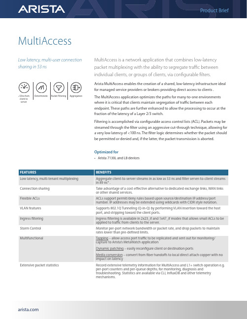
MultiAccessLow latency, multi-user connection sharing in 53 nsMultiAccess is a network application that combines low-latency packet multiplexing with the ability to segregate traffic between individual clients, or groups of clients, via configurable filters.Arista MultiAccess enables the creation of a shared, low-latency infrastructure ideal for managed service providers or brokers providing direct access to clients .The MultiAccess application optimizes the paths for many-to-one environments where it is critical that clients maintain segregation of traffic between eachendpoint. These paths are further enhanced to allow the processing to occur at the fraction of the latency of a Layer 2/3 switch.Filtering is accomplished via configurable access control lists (ACL). Packets may be streamed through the filter using an aggressive cut-through technique, allowing for a very low latency of <100 ns. The filter logic determines whether the packet should be permitted or denied and, if the latter, the packet transmission is aborted.Optimized for• Arista 7130L and LB devices<53ns from client to serverDeterministicPacket FilteringAggregation* based on lowest latency configurationLatency TablesLow Latency ModesLow latency modes are highly optimised for low latency. Features that increase the latency are disabled in these modes,including VLAN support, ingress filtering, and large ACL scale:Table 1.1 Client to Server path – Low Latency modesServer to Client latency in Low Latency modes is similar to regular MultiAccess modes, however only ACLs up to 8 rulesdeep are supported:Table 1.2 Server to Client path modes Latency for the Server to Client return path for modes supporting larger ACLs on the return path. Using 7130-LB with 10G client and 10G server port configuration asa representative sample:Table 1.4 Server to Client return path modes – larger ACLsFull Featured ModesLatency for the Client to Server path for modes supporting VLANs, ingress filtering, and larger ACLs on the return path. Using 7130-LB with 10G client and 10Gserver port configuration as a representative sample:Table 1.3 Client to Server path modes – larger ACLsArista MultiAccess for Managed Service Providers & BrokersLower-latency Exchange AccessManaged Service Providers and Brokers offer their clients access to financial exchanges and can use MultiAccess to provide significantly lower latency than typical network switches.Arista MultiAccess allows these firms to share the connection to the exchange with more than one client, while maintaining isolation between the clients. MultiAccess hence provides an ideal solution combining multiplexing (aggregation) functionality with a high-performance return path; filtering the return-path individually per client. The latter benefit from significantly lower latency in their trading connectivity as well as smaller variation in that latency.Arista MultiAccess implements a number of features which enhance this use case, for example implementing ACL filters on ingress before multiplexing, and storm control, which can avoid specific clients using an unfair amount of the network capacity.Figure 1.4 Low latency exchange accessSanta Clara—Corporate Headquarters 5453 Great America Parkway,Santa Clara, CA 95054Phone: +1-408-547-5500Fax: +1-408-538-8920Email:***************Ireland—International Headquarters3130 Atlantic AvenueWestpark Business CampusShannon, Co. ClareIrelandVancouver—R&D Office9200 Glenlyon Pkwy, Unit 300Burnaby, British ColumbiaCanada V5J 5J8San Francisco—R&D and Sales Office 1390Market Street, Suite 800San Francisco, CA 94102India—R&D OfficeGlobal Tech Park, Tower A & B, 11th FloorMarathahalli Outer Ring RoadDevarabeesanahalli Village, Varthur HobliBangalore, India 560103Singapore—APAC Administrative Office9 Temasek Boulevard#29-01, Suntec Tower TwoSingapore 038989Nashua—R&D Office10 Tara BoulevardNashua, NH 03062Copyright © 2020 Arista Networks, Inc. All rights reserved. CloudVision, and EOS are registered trademarks and Arista Networks is a trademark of Arista Networks, Inc. All other company names are trademarks of their respective holders. Information in this document is subject to change without notice. Certain features may not yet be available. Arista Networks, Inc. assumes no responsibility for any errors that may appear in this document. 09/20WAN Link MultiplexingArista MultiAccess can be used to aggregate several sources of network traffic into a WAN link and, optionally, de-multiplex from a WAN link. Often these links can be bandwidth limited (e.g. 1 GbE) with MultiAccess being able to provide a low-latency translation to and from the bandwidth-limited link. The layer 1 functionality in the Arista 7130 can be used to tap those links.To reduce the traffic volume transmitted, Arista MultiAccess can filter market data down a single, bandwidth-limited (1GbE) line. VLAN tagging and stripping can be used to multiplex multiple independent layer 2 links into a single VLAN trunk to be transmitted and then de-multiplexed. The link partner may be a traditional VLAN-aware switch, or another instance of MultiAccess.Figure 1.5 WAN Link Multiplexing。
Dell Networking W-Series 即时接入点快速入门指南说明书
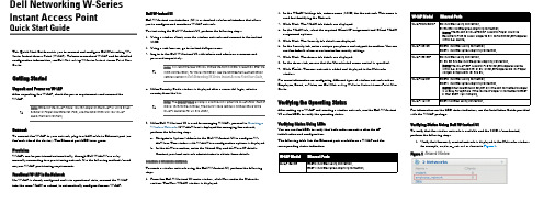
Dell Networking W-Series Instant Access PointQuick Start GuideThis Quick Start Guide assists you to connect and configure Dell Networking W-Series Instant Access Point (W-IAP). To learn more about W-IAP and for detailed configuration information, see Dell Networking W-Series Instant Access Point User Guide .Getting StartedUnpack and Power on W-IAPAfter unpacking the W-IAP, check the power requirements and connect the W-IAP .ConnectTo connect the W-IAP to your network, plug in a LAN cable to Ethernet port (on the back side of the device). The Ethernet port LED turns green.ProvisionW-IAPs can be provisioned automatically, through Dell W-AirWave or bymanually connecting to a provisioning network. Use the following methods based on your W-IAP provisioning requirements.Functional W-IAP in the NetworkIf a W-IAP is already configured and is in operational state, connect the W-IAP into the same VLAN or subnet, to automatically configure the new W-IAP.Dell W-Instant UIDell W-Instant user interface (UI) is a standard web-based interface that allows you to configure and monitor a W-IAP network.To start using the Dell W-Instant UI, perform the following steps:ing a wireless client, scan the wireless networks and connect to the instant SSID.ing a web browser, go to .3.Log in to the Dell W-Instant UI with admin and admin as username and password respectively.4.If the Country Code window is displayed after a successful login, select a country from the list.5.If the Dell W-Instant UI is used for managing W-IAPs, proceed to Creating a Wireless Network . If W-AirWave is deployed for managing the network, perform the following steps.a.Navigate to System>Admin in the Dell W-Instant UI to configure W-AirWave. The window with W-AirWave configuration options is displayed.b.In the AirWave section, enter the Shared Key and AirWave IP details. Contact your local network administrator to obtain these details.Creating a Wireless NetworkTo create a wireless network using the Dell W-Instant UI, perform the following steps:1.From the Dell W-Instant UI main window, click New under the Networks section. The New WLAN window is displayed.2.In the WLAN Settings tab, enter a name (SSID) for the network. This name is used for identifying the Network.3.Click Next . The VLAN tab details are displayed.4.In the VLAN tab, select the required Client IP assignment and Client VLAN assignment options.5.Click Next . The Security tab details are displayed.6.In the Security tab, enter a unique passphrase and retype it to confirm. You can use the default values or customize the security settings.7.Click Next . The Access tab details are displayed.8.In the Access tab, ensure that the Unrestricted access control is specified. 9.Click Finish . The new network is added and displayed in the Networks window.For more information on configuring different types of wireless network such as Employee, Guest, or Voice, see Dell Networking W-Series Instant Access Point User Guide .Verifying the Operating StatusAfter setting up a W-IAP and creating a wireless network, use the Dell W-Instant UI or the LEDs to verify the operating status.Verifying Status Using LEDsYou can use the LEDs to verify that both radios are active after the AP initialization and configuration.The following table lists the Ethernet ports available on a W-IAP and the corresponding status indication:For information on the LED status indicators, see the Installation Guide provided with the W-IAP package.Verifying Status Using Dell W-Instant UITo verify that the wireless network is available and the SSID is broadcasted, perform the following steps:1.Verify that the newly created network is displayed in the Networks window: for example, employee_network as shown in Figure 1.Figure 1Network WindowW-IAP ModelEthernet PortsW-IAP134/135ENET0: Indicates uplink connection.ENET1: Indicates wired downlink connection.W-IAP3WN/3WNPE0: Indicates uplink connection.E1 and E2: Indicate wired downlink connection.NOTE: The E2 port on W-IAP3WNP supports Power SourcingEquipment (PSE) to supply power to any compliant 802.3af powered (class 0-4) device.W-IAP108/109ENET0: Indicates uplink connection.ENET1: Indicates wired downlink connection.W-IAP155/155PE0: Indicates uplink connection.E1, E2, E3, and E4: Indicate wired downlink connection.NOTE: The W-IAP155P supports PSE for 802.3at powered device (class 0-4) on one port (E1 or E2), or 802.3af powered DC IN (Power Socket) on two ports (E1 and E2).W-IAP224/225ENET0: Indicates uplink connection.ENET1: Indicates wired downlink connection.NOTE: When operating on 802.3af, only the port connected to power is usable. For example, if the source of power is connected to ENET 0, then ENET 1 will not work.W-IAP114/115ENET: Indicates uplink connection.Dell Networking W-Series Instant Access Point | Quick Start Guide Part Number 0511486-02 | December 2013Dell Networking W-SeriesInstant Access PointQuick Start GuideContacting DellMain Website Contact Information /contactdell Support Website /support Documentation Website/support/manualsCopyright© 2013 Aruba Networks, Inc. Aruba Networks trademarks include , Aruba Networks®, Aruba Wireless Networks®, the registered Aruba the Mobile Edge Company logo, and Aruba Mobility Management System®. Dell™, the DELL™ logo, and PowerConnect™ are trademarks of Dell Inc.All rights reserved. Specifications in this manual are subject to change without notice.Originated in the USA. All other trademarks are the property of their respective owners.Open Source CodeCertain Aruba products include Open Source software code developed by third parties, including software code subject to the GNU General Public License (GPL), GNU Lesser General Public License (LGPL), or other Open Source Licenses. Includes software from Litech Systems Design. The IF-MAP client library copyright 2011Infoblox, Inc. All rights reserved. This product includes software developed by Lars Fenneberg, et al. The Open Source code used can be found at this site:/open_source Legal NoticeThe use of Aruba Networks, Inc. switching platforms and software, by all individuals or corporations, to terminate other vendors’ VPN client devices constitutes complete acceptance of liability by that individual or corporation for this action and indemnifies, in full, Aruba Networks, Inc. from any and all legal actions that might be taken against it with respect to infringement of copyright on behalf of those vendors.2.Disconnect the client from instant , the default provisioning network to which your client system is connected.3.Connect your client to the newly created network.4.Log in to the Dell W-Instant UI with the administrator credentials. The instant provisioning network is automatically deleted and will no longer be available.Converting a W-IAPA W-IAP can be converted to operate as a Campus AP or Remote AP managed by a Dell Networking W-Series Mobility Controller.To convert a W-IAP through the Dell W-Instant UI, perform the following steps:1.Log in to the Dell W-Instant UI with the administrator credentials.2.Click the Maintenance link at the top right corner of the Dell W-Instant main window.3.Click the Convert tab.4.Based on your requirement, select an appropriate option from the Convert one or more Access Points to drop-down menu.5.Enter the IP address of the Dell Mobility Controller.6.Click Convert Now . The W-IAP reboots and begins operating in the mode that you configured. To convert a W-IAP from a controller-managed mode to Dell W-Instant mode,manually reset the W-IAP.For more information on the W-IAP conversion process, see the Dell Networking W-Series Instant Access Point User Guide .。
WLN00100-无线局域网控制器(WLC)最优配置方法
【标题】无线局域网控制器(WLC)最优配置方法【译者姓名】彭国勇【校对人】【翻译完成时间】2008-1-19【原文英文标题】Wireless LAN Controller (WLC) Configuration Best Practices【原文链接】/en/US/tech/tk722/tk809/technologies_tech_note09186a008081088 0.shtml【翻译内容】目录介绍 (2)先决条件 (2)要求 (2)使用组件 (2)公约 (3)最佳做法 (3)无线/射频 (3)网络连接 (4)网络设计 (8)移动性 (8)安全 (13)总结 (16)如何把WLC 崩溃文件从WLC传输到TFTP服务器 (21)本文档提供了WLC的简短配置窍门,包括在TAC中心常见的几个有关无线统一基础设施问题。
该文档适用于大多数网络实现环境,以便最大限度减少可能发生的问题。
注意:并不是所有的网络都是等同的,因此,一些建议可能并不适用于您的网络安装环境。
总是需要核实,然后再进行一些更改。
先决条件要求思科建议您了解这些议题:∙了解如何配置无线局域网控制器( WLC )和轻量级接入点(LAP)的基本操作∙轻量级接入点协议( LWAPP )和无线安全的基本知识使用组件此文档中的信息是基于这些软件和硬件版本:∙思科2000/2100/4400系列WLC ,运行软件版本在4.2或5.0∙LWAPP的接入点, 1230,1240,1130,10x0和1510 系列本文件中所涉及的设备均在特定的实验室环境。
本文件中使用所有设备开始为默认配置,在配置网络之前,要确保了解潜在影响的任何命令。
在文件公约中,如了解更多信息请参考Cisco Technical Tips Conventions 连接。
最佳做法无线/射频对于无线/射频( RF )最佳做法如下:∙对于任何无线部署,前期必须要进行一个适当的实地勘察,以确保为无线用户提供适当的服务质量。
set_ideal_network -no_propagation用法 -回复
set_ideal_network -no_propagation用法-回复“set_ideal_network no_propagation用法”指的是在构建神经网络时,采用了无传播(no propagation)的理想网络(ideal network)设置。
本文将逐步介绍这个用法,包括它的定义、作用、使用场景以及具体操作步骤。
通过阐述这些内容,读者将能够深入了解set_ideal_networkno_propagation的用途和实践方法。
一、定义与作用在开始之前,我们先来了解“set_ideal_network no_propagation”的定义和作用。
set_ideal_network是指在神经网络构建的过程中,创建一个没有传播的理想网络。
no_propagation表示网络在训练过程中不进行传播,即不计算梯度。
这种设置的主要作用是为了比较网络在完全无传播的情况下的性能表现。
通过与其他传统的网络进行对比,可以验证传统网络中传递的信息对模型的训练和性能产生的影响。
二、使用场景接下来,我们来探讨一些使用set_ideal_network no_propagation的典型场景。
这种设置通常用于以下情况:1. 网络设计和优化:理想网络的设置可以帮助设计者更好地理解各个网络层级之间的复杂关系,提供参考用于优化网络的结构和参数。
2. 梯度分析和网络评估:通过与传统网络进行比较,可以分析并评估梯度对训练过程和模型效果的影响。
这有助于深入研究网络的训练机制以及隐藏层间的信息流动。
3. 比较不同模型结构:使用理想网络进行比较可以帮助研究人员更好地理解不同模型结构对学习能力和权重更新的影响,进而优化网络架构。
三、操作步骤现在,我们将介绍一些具体的操作步骤来使用set_ideal_networkno_propagation。
1. 定义理想网络:首先,我们需要定义一个不进行传播的理想网络。
这可以通过在定义网络模型时注意不进行反向传播来实现。
WRFChem Users Guide

The following institutions were instrumental in the development of the WRF-Chem model and its documentation. Department of Commerce/National Oceanic and Atmospheric Administration The Cooperative Institute for Research in Environmental Sciences The University Corporation for Atmospheric Research (UCAR) The National Center for Atmospheric Research (NCAR) The Max Plank Institute The University of Chile Centro de Previsão de Tempo e Estudos Climáticos This document does not constitute endorsement of the information, products or services contained herein by the contributing institutions previously named or unnamed. For other than authorized activities, the contributing institutions do not exercise any editorial control over the information contained herein. Any opinions, findings, conclusions or recommendations expressed in this document are those of the authors and do not necessarily reflect those of the contributing institutions. In no event shall these institutions, or any unmentioned institution associated with WRF-Chem development, be liable for any damages, whatsoever, whether direct, indirect, consequential or special, that arise out of or in connection with the access, use or performance of WRF-Chem, including infringement actions. The Weather Research and Forecasting model (WRF hereafter) was developed at the National Center for Atmospheric Research (NCAR) that is operated by the University Corporation for Atmospheric Research (UCAR). NCAR and UCAR make no proprietary claims, either statutory or otherwise, to this version and release of WRF and consider WRF to be in the public domain for use by any person or entity for any purpose without any fee or charge. UCAR requests that any WRF user include this notice on any partial or full copies of WRF. WRF is provided on an “AS IS” basis and any warranties, either express or implied, including but not limited to implied warranties of non-infringement, originality, merchantability and fitness for a particular purpose, are disclaimed. In no event shall UCAR be liable for any damages, whatsoever, whether direct, indirect, consequential or special, which arise out of or in connection with the access, use or performance of WRF, including infringement actions.
- 1、下载文档前请自行甄别文档内容的完整性,平台不提供额外的编辑、内容补充、找答案等附加服务。
- 2、"仅部分预览"的文档,不可在线预览部分如存在完整性等问题,可反馈申请退款(可完整预览的文档不适用该条件!)。
- 3、如文档侵犯您的权益,请联系客服反馈,我们会尽快为您处理(人工客服工作时间:9:00-18:30)。
BrochureMore information from /reports/2171649/Modelling the Wireless Propagation Channel. A simulation approach with Matlab. Wireless Communications and Mobile ComputingDescription: A practical tool for propagation channel modeling with MATLAB® simulations.Many books on wireless propagation channel provide a highly theoretical coverage, which for someinterested readers, may be difficult to follow. This book takes a very practical approach by introducing thetheory in each chapter first, and then carrying out simulations showing how exactly put the theory intopractice. The resulting plots are analyzed and commented for clarity, and conclusions are drawn andexplained from the obtained results.Key features include:A unique approach to propagation channel modeling with accompanying MATLAB® simulations todemonstrate the theory in practiceContains step by step commentary and analysis of the obtained simulation results in order to provide acomprehensive and structured learning toolCovers a wide range of topics including shadowing effects, coverage and interference, MultipathNarrowband channel, Multipath Wideband channel, propagation in micro and pico–cells, the land mobilesatellite (LMS) channel, the directional Multipath channel and MIMO and propagation effects in fixed radiolinks (terrestrial and satellite)The book comes with an accompanying website that contains the MATLAB® simulations and allows readersto try them out themselvesWell suited for lab–use, as reference and as a self–learning tool both for advanced students andprofessionalsModeling the Wireless Propagation Channel: A simulation approach with MATLAB® will be best suited forpostgraduate (Masters and PhD) students and practicing engineers in telecommunications and electricalengineering fields, who are seeking to familiarise themselves with the topic without too many formulas. Thebook will also be of interest to network engineers, system engineers and researchers.Contents:ContentsAbout the Series EditorsPrefaceAcknowledgments1Introduction to Wireless Propagation1.1 Introduction1.2 Wireless Propagation Basics1.3 Link Budgets1.4 Projects1.5 SummaryReferencesSoftware Supplied2Shadowing Effects2.1 Introduction2.2 Projects2.3 SummaryReferencesSoftware Supplied3Coverage and Interference3.1 Introduction3.2 Hata Model3.3 Projects3.4 SummaryReferencesSoftware Supplied4Introduction to Multipath4.1 Introduction4.2 Projects4.3 SummaryReferencesSoftware Supplied5Multipath: Narrowband Channel5.1 Introduction5.2 Projects5.3 SummaryReferencesSoftware Supplied6Shadowing and Multipath6.1 Introduction6.2 Projects6.3 SummaryReferencesSoftware Supplied7Multipath: Wideband Channel7.1 Introduction7.2 Deterministic Multiple Point–Scatterer Model 7.3 Channel System Functions7.4 Stochastic Description of the Wireless Channel 7.5 Projects7.6 SummaryReferencesSoftware Supplied8Propagation in Microcells and Picocells8.1 Introduction8.2 Review of Some Propagation Basics8.3 Microcell and Picocell Empirical Models8.4 Projects8.5 SummaryReferencesSoftware Supplied9The Land Mobile Satellite Channel9.1 Introduction9.2 Projects9.3 SummaryReferencesSoftware Supplied10The Directional Wireless Channel10.1 Introduction10.2 MIMO Systems10.3 Projects10.4 SummaryReferencesSoftware SuppliedIndexOrdering:Order Online - /reports/2171649/ Order by Fax - using the form belowOrder by Post - print the order form below and send toResearch and Markets,Guinness Centre,Taylors Lane,Dublin 8,Ireland.Fax Order FormTo place an order via fax simply print this form, fill in the information below and fax the completed form to 646-607-1907 (from USA) or +353-1-481-1716 (from Rest of World). If you have any questions please visit/contact/Order Information Please verify that the product information is correct.Product Format Please select the product format and quantity you require:* Shipping/Handling is only charged once per order.Contact InformationPlease enter all the information below in BLOCK CAPITALSProduct Name:Modelling the Wireless Propagation Channel. A simulation approach with Matlab.Wireless Communications and Mobile Computing Web Address:/reports/2171649/Office Code:SCD2KSXH QuantityHard Copy (HardBack):USD 121 + USD 29 Shipping/HandlingTitle:MrMrsDrMissMsProf First Name:Last Name:Email Address: *Job Title:Organisation:Address:City:Postal / Zip Code:Country:Phone Number:Fax Number:* Please refrain from using free email accounts when ordering (e.g. Yahoo, Hotmail, AOL)Payment InformationPlease indicate the payment method you would like to use by selecting the appropriate box.Please fax this form to:(646) 607-1907 or (646) 964-6609 - From USA+353-1-481-1716 or +353-1-653-1571 - From Rest of World Pay by credit card:You will receive an email with a link to a secure webpage to enter yourcredit card details.Pay by check:Please post the check, accompanied by this form, to:Research and Markets,Guinness Center,Taylors Lane,Dublin 8,Ireland.Pay by wire transfer:Please transfer funds to:Account number833 130 83Sort code98-53-30Swift codeULSBIE2D IBAN numberIE78ULSB98533083313083Bank Address Ulster Bank,27-35 Main Street,Blackrock,Co. Dublin,Ireland.If you have a Marketing Code please enter it below:Marketing Code:Please note that by ordering from Research and Markets you are agreeing to our Terms and Conditions at /info/terms.asp。