VAG 操作手册-RIKO-活塞阀-中文
阿法拉伐无菌取样阀中文版

及冰激凌等。
Keofitt无菌取样阀W9型阀门可配备有微型接口,以便用户能够使用皮下注射用针头进行取样操作。
接式连接端口,也有卡箍式连接端口或带螺纹式的端口。
阀体:T型:适用于罐体连接(焊接式)。
P型:适用于管道连接(焊接式)。
C型:卡箍式。
S型:插口式(带螺纹)。
阀门头H型:转动把手。
a.开启阀门,取样K型:钥匙。
N型:气动式。
该款型阀门已经得到授权可以使用3A标记。
b.关闭阀门,灭菌消毒操作图1工作原理尺寸(mm)阀门位置M4W9A7090B49C58 D(罐体)2828D(管道)25或2825或28D(卡箍)2550(1/2"卡箍)(1"卡箍) D(插口)M28x1.5M28x1.5E4768材料阀体:.................不锈钢,1.4404(316L)阀头:.................不锈钢,301,303,316L薄膜:.................硅橡胶(标准型阀门用)EPDM橡胶(带微型接口的阀门用)技术数据压力阀座上最大.............工作压力(关闭阀门):........600kPa(6巴)阀盖上最大.............工作压力(开启阀门):........橡胶材料:1200kPa(12巴)不锈钢材料:1500kPa(15巴)温度最大灭菌消毒温度,干蒸汽(2-3巴):121-134℃。
蒸汽务必是干的,因为冷凝水会损坏薄膜。
我们向用户建议,每100次取样操作或灭菌消毒操作之后,应该更换薄膜片,或者也可以根据工作条件或经验进行更换。
Valve粘度M40-100cPW90-1000cP W150-50000cPW250-250000cP 可选项A.阀头的钥匙链,型号K。
B.用于进行气动操作的阀门头,型号N(“A”尺寸要放大)。
C.阀头,型号H及K,带微型接口,用于W9型。
D.阀头,型号B(阻断型)不带弹簧,可在出现压力冲击(手柄为红色)危险的情况下使用产品订购用户在订购时,请说明以下事项:-阀门规格,M4型或者是W9型。
调流调压阀运行维护手册
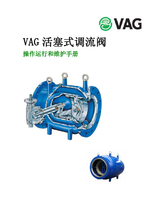
VAG活塞式调流阀 操作运行和维护手册目录1、概述 12、标示 23、应用范围 24、驱动(执行)装置 25、运输及储存 36、安装 37、调试和试运行 48、拆卸阀门的安全事项 59、阀门的现场测压 510、维护保养 511、运行极限 612、最大操作扭力矩 613、执行器的安装 614、设计—零部件更换 71、概述所有的V AG阀门产品都是按照国际设计与工程标准设计和制造的。
原则上,他们都是安全的,然而,如果他们被不正当地应用,或使用在超出设计应用范围之外,那么,他们也可以变成危险的制造者。
在用户公司,每一个涉及和参与阀门的安装、调试、零部件更新、维护保养和操作的人都必须认真完整地阅读和理解本操作手册。
在拆除任何阀门的保护设施和/或对阀门进行安装测试之前,都必须确保与之相连的管道区域被从整个系统中隔离出来。
尽可能地避免风险。
任何未授权的、错误和突然性的操作必须被防止,同时也要小心察看以保证释放掉任何形式的能量(如压缩空气,带压的水等)。
当使用阀门时,必须遵守工程指示;如:DIN标准,DVGW指示,VDI指示等。
如果要将保压管道末端的阀门打开,要保证流出的水流不会损坏或伤及其他。
在关阀时,必须设立警告标志,因为任何试图在阀体和活塞之间的阻止阀门关闭的人都将受到伤害。
如果从管线上卸掉阀门,都会有水渗漏出来。
在卸载阀门之前,应尽可能地清空管线,同时要小心残留物。
2、标示依照DIN EN 19的要求,每一个阀门都被标记公称直径、公称压力、阀体材质和制造商。
V AG产品的铭牌上有下列信息:制造商V AG的名字;阀门的公称直径;阀门的公称压力;控制单元;阀体材质:铸钢;制造日期。
3、应用范围V AG 活塞调流阀能更优越的应用于流量,压力,水位的控制,特别在高压差和大流量的供水及能量供应系统中及工业处理工程中。
4、驱动(执行)装置手动减速箱、气动执行器和电动执行器等驱动装置都是按照DIN EN 1074-1的规定设计的,任何有别于此规定的操作条件,制造商都应该做出说明。
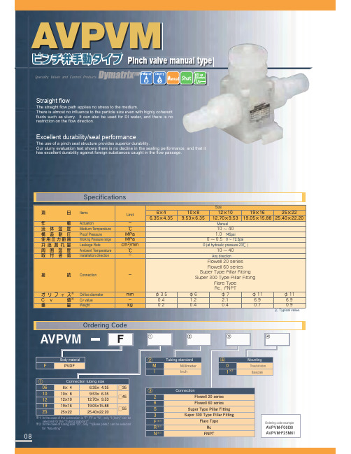
自动真空阀 AVPVM-F R N 产品手册说明书
ʷ
ʷ
˘
ʷ ʷ
ʷ ʷ
˘
ʷ ʷ
ʷ ʷ
˘
˞1: In the case of the connection is "F","R" or "N", only "I (Inch)" can be selected for the "Tubing Standard".
'MPXFMMTFSJFT
'MPXFMMTFSJFT " 4VQFS5ZQF1JMMBS'JUUJOH
4VQFS5ZQF1JMMBS'JUUJOH 'MBSF5ZQF 3Dɺ'/15
# $ % & ' ( )
4UBOEBSE
JODI NN JODI NN JODINN JODINN JODI JODI
ᶅ ̨ ̛˞ ̧˞ ̣˞
Connection 'MPXFMMTFSJFT 'MPXFMMTFSJFT
4VQFS5ZQF1JMMBS'JUUJOH 4VQFS5ZQF1JMMBS'JUUJOH
'MBSF5ZQF 3D
'/15
Ordering code example
Unit
ʵ ˆ .1B .1B DNNJO ˆ ʵ
ଓ Connection
ʵ
Φ Ϧ ϑ Ο ε˞ Orifice diameter
NN
$ W ɹ ˞ Cv value
ʵ
ॏ
ྔ Weight
LH
ʷ ʷ
П
Size
瓦尔特兵卒1控制阀使用指南说明书

Valtek Trooper1Valtek Trooper2The Valtek ® Trooper valve is a high-performance,general-service control valve with a high-thrust dia-phragm actuator. The valve is designed for use in ANSI Class 150 or 300 service applications with temperatures ranging from -20° to 650° F / -30° to 345° C.In addition to its high thrust, the reversible actuator is compact. An optional integral I/P or P/P positioner ensures high positioning accuracy proportional to the valve instrument signal. The integrally mounted posi-tioner eliminates external tubing requirements, reduces pinch points and keeps moving parts safe from external dirt and damage. Reversing the actuator does not require positioner, tubing changes or extras parts.The actuator accepts air supply pressures up to 60 psig / 4 Barg allowing the valve to shutoff against high-pressure drops. Different spring-sets are available to meet individual application requirements. Removing the reversible actuator from the valve is easy with the unique yoke design and yoke clamps.Many of the standard Mark One valve features are included in the Trooper general service valve including heavy duty, stem guides; self-centering, clamped-in seat ring; raised face integral flanges, multiple trim reductions and easy top-entry valve accessibility.The Trooper valve is available in 1, 11/2, 2, 3 and 4-inch valve sizes and with carbon steel or stainless steel bodies. Valve sizes 1 through 2-inch are also available in socketweld or NPT end connections.The Trooper control valve is the solution for most general-service applications.TMGeneral Service Control ValvesValtek TrooperFeatures & Advantages3Valtek Trooper Options / Flow Capacity4Valtek TrooperTechnical DataTable III: Actuator Data3 lbs / 1.4 kg for I/P positioner.5Valtek Trooper* Per ANSI/ISA S75.03, 1985; ANSI/ISA S75.12, 1987. Socketweld and NPT end connections are available on 1 through 2-inch valves with equivalent face-to-face dimensions.** With top-mounted handwheel add 3.6 in. / 91 mm to actuators sizes 48, 38, 38 I/P; add 4.9in. / 124 mm to actuator sizes 49, 39, 39 I/P.All trademarks and tradenames shown in this literature are the property of their respective owners.DimensionsTable VI: Dimensions (inches /mm )Flowserve Corporation has established industry leadership in the design and manufacture of its products. When properly selected, this Flowserve product is designed to perform its intended function safely during its useful life. However, the purchaser or user of Flowserve products should be aware that Flowserve products might be used in numerous applications under a wide variety of industrial service conditions. Although Flowserve can (and often does) provide general guidelines, it cannot provide specific data and warnings for all possible applications. The purchaser/user must therefore assume the ultimate responsibility for the proper sizing and selection, installation, operation and maintenance of Flowserve products.The purchaser/user should read and understand the Installation Operation Maintenance (IOM) instructions included with the product, and train its employees and contractors in the safe use of Flowserve products in connection with the specific application.While the information and specifications presented in this literature are believed to be accurate, they are supplied for informative purposes only and should not be considered certified or as a guarantee of satisfactory results by reliance thereon. Nothing contained herein is to be construed as a warranty or guarantee, express or implied, regarding any matter with respect to this product. Because Flowserve is continually improving and upgrading its product design, the specifications, dimensions and information contained herein are subject to change without notice. Should any question arise concerning these provisions, the purchaser/user should contact Flowserve Corporation at any of its worldwide operations or offices.。
avk工业阀门 - 产品手册说明书
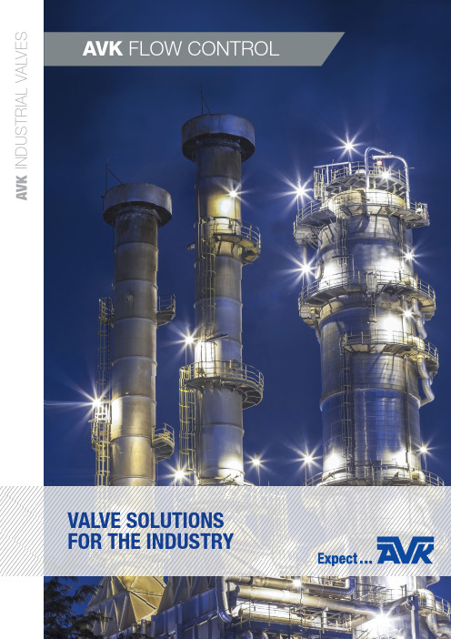
valve solutions for the industryAVK FLOW CONTROLA V K I N D U S T R I A L V A L V E SFLOW CONTROLavK industrial valvesThe resent years’ acquisitions of companies has now formed the basis for a new AVK business area – called AVK Industrial Valves. Here, a wide range of competences have been unified with the purpose to deliver more than just high quality products, but to deliver solutions that help optimise our customers´ businesses.Each of the companies and their respective partners operating within the AVK Industrial Valves business unit has comprehensive expertise within customised valves and accessories, as well as complete solutions.Wouter WitZel orbinoX interaPP World-valve tec artecProduct solutions to oWn sales channelsavK industrial valves coMPaniesFor 40 years, the Dutch company Wouter Witzel has been a leading international manufacturer and supplier of high quality industrial butterfly valves and actuators. The products are used in pipelines as shut-off valves, control valves, and non-return valves. A full range of manual control devices, actuators, and accessories is available for specific conditions.World-Valve is exceptionally adept at grasping and solving specific challenges in specific markets. Within their focus areas of expertise they have invested tremendous amounts of time and effort into charting and understanding all relevant circumstances and requirements. Their knowledge and experience thus gained, translates into quickly delivered quality solutions.Headquartered in Rotkreuz, Switzerland, InterApp operates its own research and development as well as manufacturing, assembly and testing facilities in Switzerland and in Spain. With more than 40 years of experience, InterApp sets technological standards with their proprietory valve and fluid technology.TEC artec with main location in Germany has more than twenty years of experience in engineering special valve products for high pressure and high temperature applications, industrial auxiliary equipment for power plants, gas and oil industry and the petro chemical industry.Wouter WitZel World valveinteraPPtec artecAVK INDUSTRIAL VALVESbrand: industrial valve coMPaniesORBINOX is one of the world’s leading producers of knife gate valves and is present in more than 70 countries worldwide with over 50 years of experience designing, manufacturing, and marketing knife gate valves, penstocks, dampers, and valves for hydraulic works.orbinoX010203eXPect aPPlication KnoWledGe and understandinGeXPectcoMPetent local suPPorteXPect internationalcoordinationsuPPorted by the leadinG coMPanies and Manufacturersof industrial valves, you can eXPect hiGh consistentQuality and serviceavK floW controlAVK FLOW CONTROL delivers optimal valve solutions based on application knowledge and understanding, competentlocal support and international coordination.At AVK FLOW CONTROL, we focus on four main target segments. In this way we are able to heighten the quality of oursolutions, and be closer to our customers at all times.OPTIMAL valve solutionsFOR POWER GENERATIONOPTIMAL valve solutionsFOR THE MINING INDUSTRYOPTIMAL valve solutionsFOR OIL AND GASOPTIMAL valve solutionsFOR WATER TREATMENT PoWer Generationoil and GasMininG industryWater treatMentenGineerinG Pneuton tMseGMent sales ofvalve solutionsavK floW controlsales oc’sbrand: industrial valve coMPaniesindustrial valve headQuaters and avK floW controlentities on selected MarKets.AVK FLOW CONTROLindustrial valves headQuarters:avK floW control a/sKaretmagervej 57100 VejleDenmarkTel.: +45 7585 8408Wouter WitZelIndustrieterrein De Pol 12P.O. Box 54NL-7580 AB LosserThe NetherlandsTel: +31 53 536 95 36Fax: +31 53 536 95 00*******************www.wweurovalve.nlWorld valveLeusinkweg 5-aP.O. Box 1467580 AC LosserThe NetherlandsTel: +31 53 538 1295Fax: +31 53 538 7505*******************orbinoXPº Mikeletegi, 5620009Donostia - San SebastianSpainTel: +34 943 69 80 30Fax: +34 943 65 30 66***************tec artecAm Heidering 7aGewerbepark NordD-16515 OranienburgGermanyTel.: +49 3301 20 32 60Fax: +49 3301 20 32 70interaPPGrundstrasse 24CH-6343 RotkreuzSwitzerlandTel: +41 (0) 41 798 22 33Fax: +41 (0) 41 798 22 34****************.netavK floW controlaustralia6 Wirriga StreetRegency Park, SA 5010AustraliaTel: +61 8 8262 8885Fax: +61 8 8262 7071************************.au.auorbinoX uK /avK floW control uKUnits 6-7 Clock ParkShripney RoadBognor Regis-West SussexPO22 9NHEngland, UKTel: +44 1243 810240Fax: +44 1243 87 00 40**************avK floW controlMiddle east119- Grand Hamad StreetMaackeen HoldingFirst Floor - D122Doha – State Of QatarPhone: +974 44 41 51 81avK floW controlsinGaPore11 Changi North Street 1,#03-11, 498823 SingaporeTel: +65 6542 0451denMarKaustraliauK & irelandMiddle eastsinGaPorevictoria & tasMania T: +61 447 461 908neW south Wales & neW Zealand T: +61 475 959 651T: +61 8 9303 2690F: +61 8 9302 2136E:**************************.au Perth Unit 1, 61 Prosperity Avenue Wangara, WA 6065AustraliaT: +61 8 9022 7228F: +61 8 9022 7230E:***************************.au KalGoorlie2/15 William StreetWest Kalgoorlie, WA 6430Australia T: +61 8 8262 8885F: +61 8 8262 7071E:************************.au head office 559A Grand Junction Road Wingfield, SA 5013Australia T: +61 7 3277 7054F: +61 7 3277 0591E:***************************.aubrisbane67 Musgrave RoadCooper Plains, QLD 4108AustraliaavK floW control Pty ltd .au。
ASAHI AV 膜式阀门 Type 15 用户手册说明书

Serial No. H-V031-E-8Diaphragm Valves Type 15User’s ManualContents(1) Be sure to read the following warrantyclauses of our product 1(2) General operating instructions 2(3) General instructions for transportation,unpacking and storage 3(4) Name of parts 4(5) Working pressure vs. temperature 6(6) Specification of limit switch 7procedure7Installation(7)(8) Connection of limit switch procedure 8(9) Operating procedure 9(10) Adjustment procedure for stopper 10(11) Diaphragm replacement procedure 11Inspectionitems 12(12)Troubleshooting12(13)(14) Handling of residual and12wastematerialsThis user’s guide contains information important to the proper installation, maintenance and safe use of an ASAHI AV Product. Please store this manual in an easily accessible location.<Warning & Caution Signs>This symbol reminds the user to take caution due to the potential for serious injury or death.This symbol reminds the user to take caution due to the potential for damage to the valve if used in such a manner.<Prohibited & Mandatory Action Signs>Prohibited: When operating the valve, this symbol indicates an action that should not be taken.Mandatory action: When operating the valve, this symbol indicates mandatory actions that must be adhered to.(1) Be sure to read the following warranty clauses of our product- Always observe the specifications of and the precautions and instructions on using our product.- We always strive to improve product quality and reliability, but cannot guarantee perfection. Therefore, should you intend to use this product with any equipment or machinery that may pose the risk of serious or even fatal injury, or property damage, ensure an appropriate safety design or take other measures with sufficient consideration given to possible problems. We shall assume no responsibility for any inconvenience stemming from any action on your part without our written consent in the form of specifications or other documented approval.- The related technical documents, operation manuals, and other documentation prescribe precautions on selecting, constructing, installing, operating, maintaining, and servicing our products. For details, consult with our nearest distributor or agent.- Our product warranty extends for one and a half years after the product is shipped from our factory or one year after the product is installed, whichever comes first. Any product abnormality that occurs during the warranty period or which is reported to us will be investigated immediately to identify its cause. Should our product be deemed defective, we shall assume the responsibility to repair or replace it free of charge.- Any repair or replacement needed after the warranty period ends shall be charged to the customer. - The warranty does not cover the following cases:(1) Using our product under any condition not covered by our defined scope of warranty.(2) Failure to observe our defined precautions or instructions regarding the construction, installation, handling,maintenance, or servicing of our product.(3) Any inconvenience caused by any product other than ours.(4) Remodeling or otherwise modifying our product by anyone other than us.(5) Using any part of our product for anything other than the intended use of the product.(6) Any abnormality that occurs due to a natural disaster, accident, or other incident not stemming fromsomething inside our product.WarningCaution(2) Generaloperating instructions- Using a positive-pressure gas with our plastic piping may pose a dangerous condition due to the repellent force particular to compressible fluids even when the gas is under similar pressures used forliquids.Therefore, be sure to take the necessary safety precautions such as covering the piping with protective material. For inquiries, please contact us. For conducting a leak test on newly installed piping, be sure to check for leaks under water pressure. If absolutely necessary to use a gas in testing, please consult your nearest service station beforehand.- Do not step on or apply excessive weight on valve. (It can be damaged.)- Do not use the valve in conditions where the fluid may have crystallized.(The valve will not operate properly.) - Keep the valve away from excessive heat or fire. (It can be damaged, or destroyed.)- Always operate the valve within the pressure vs. temperature range.(The valve can be damaged or deformed by operating beyond the allowable range.)- Allow sufficient space for maintenance and inspection.- Select a valve material that is compatible with the media. For chemical resistance information, refer to “CHEMICAL RESISTANCE ON ASAHI AV VALVE”. (Some chemicals may damage incompatible valve materials.)- Keep the valve out of direct sunlight, water and dust. Use cover to shield the valve. (The valve will not operate properly.)- Perform periodic maintenance.(Leakage may develop due to temperature changes or periods of prolonged storage, rest, or operation.) - The travel stop may have to be adjusted if media leakage is detected between the upstream & downstream sides of the valve.- Bonnet bolt torque should be checked before installation, as they may become loose after long-term storage. A periodic check of the valve condition as well as bonnet & flange bolt torque should be made part of preventative maintenance program properly re-tightening the bolts as necessary. It is especially important to re-tighten all bolts during the first shutdown.Nom. Size mm (inch)Bonnet tightening torque valueN ・m {kgf ・cm} [lb ・inch]Rubber PTEF 125 (5)45.0 {459} [400] 45.0 {459} [400] 150 (6)45.0 {459} [400]45.0 {459} [400]WarningCaution(3) General instructions for transportation, unpacking and storage- When suspending and supporting a valve, take care and do not stand under a suspended valve.- This valve is not designed to handle impacts of any kind. Avoid throwing or dropping the valve. - Avoid scratching the valve with any sharp object.- Do not over-stack cardboard shipping boxes. Excessively stacked packages may collapse. - Avoid contact with any coal tar creosote, insecticides, vermicides or paint. (These chemicals may cause damage to the valve.) - When transporting a valve, do not carry it by the handle. - Store products in their corrugated cardboard boxes. Avoid exposing products to directsunlight, and store them indoors (at room temperature). Also avoid storing products in areas with excessive temperatures. (Corrugated cardboard packages become weaker as they become wet with water or other liquid. Take care in storage and handling.)- After unpacking the products, check that they are defect-free and meet the specifications.Warning Caution(4) Name of partsNominal Size: 125, 150mm (5”, 6”)No. DESCRIPTION No. DESCRIPTION No. DESCRIPTION[20] Nut[1] Body [9] Sleeve(A)[1a] Inserted Nut [10] Thrust bearing(A) [21] Gauge cover[2] Bonnet [11] O-ringliner(A) [22] BonnetNipple [23] Stud bolt・nut[3] Diaphragm [12] Grease[3a] Inserted metal of DIA [13] Hand wheel [24] Bolt・Nut[4] Cushion [14] Name Plate [26] Body liner[4a] Cushion cover [15] Cap [27] Rib linerring [28] U-bolt・nut[5] Compressor [17] SheetConicalwasherspring[18] Stopper [29]Pin[7]Compressorwasher[8] Stem [19]Spring[22], [26], [27], [28], [29] are used with special specification.Nominal Size: 125, 150mm (5”, 6”) with Limit Switch (Option)No. DESCRIPTION No.DESCRIPTION[36] Limit Switch [38]Nut (A)[37] Bracket (A) [40]Limit Switch Rod(6) Specification of limit switch (option)Nominal Size Type CodeProtection Grade125, 150mm (5”, 6”)1LS1-J IP67Limit Switch Rating Connection Rate Voltage (V) Resistive Load (A) Inductive Load (A)AC125 10 6 AC250 10 6 DC115 0.8 0.2 DC230 0.4 0.1(7) Installation procedure- When suspending and supporting a valve, take care and do not stand under a suspended valve.- Be sure to conduct a safety check on all hand and power tools to be used before beginning work. - Wear protective gloves and safety goggles as fluid remain in the valve even if the pipeline is empty. (You may be injured.)- When installing a pipe support by means of a U-band or something similar, take care not to over-tighten. (Excessive force may damage the pipe.)- When installing pipes and valves, ensure that they are not subjected to tension, compression, bending, impact, or other excessive stress.- When installing, disassembling, or reassembling the piping, fix the End Connector.- When connecting an ASAHI AV Valve to metal piping, take care not to let the pipe stress on the ASAHI AV Valve.- Be sure to use sealing gaskets (AV Gasket), bolts, nuts, and washers and tighten them to specified torques. (When a non-AV gasket is used, a different tightening torque specification should be followed.)Procedure1) Set the AV gasket between the flanges.2) Insert washers and bolts from the pipe side, insert washers and nuts from the valve side, then temporarily tightenthem by hand.WarningCaution3) Using a torque wrench, tighten the bolts and nuts gradually to the specified torque in a diagonal manner (Refer to fig.1.)Specified torque value Unit : N ・m {kgf ・cm }[lb ・inch]Nom. Size 125mm (5”) 150mm (6”) Torque value40.0{408} [355]40.0{408} [355]- Tighten the bolts and nuts gradually with a torque wrench to the specifiedtorque level in a diagonal manner.(8) Connection of limit switch procedure (option)- Shut down the power on the equipment before connecting wires. There are risks of electrical shock depending on the level of operating voltage.- Be sure that the terminal cover and body cover are put on during the operation. - If you use the limit switch at 1mA-100mA or 5-30V, consult near Asahi dealer.CautionCautionCautionWarningProcedure1) Loosen the three screws used to attach the limit switch cover with ascrewdriver (+) and remove the cover from the limit switch. *These screws are captive.2) Pull and remove the protective cap, made of resin, from the cover.3) Draw the cable through the connector.4) Strip the cable with a wire stripper.5) Install a crimp-style terminal on the lead wire with a terminalcrimping tool.6) Connect the terminal screw with a screwdriver (+) according to the internal circuit diagram show in page 7.* Tighten the screws.(If not, electric leaks or shocks may occur.)7) Tighten the above three screws with a screw driver (+) to install the cover on the limit switch.8) Tighten the cable by connector.(9) Operating procedure- Do not exert excessive force in closing the valve.- Do not use the valve to fluid containing slurry. (The valve will not operate properly.)- The installed valve must never be opened or closed when foreign matter such as sand is present in the pipeline.- When operating the handle, be sure to do so with your hand. (Using a tool may damage the handle.) - If a stopper is loose, adjust it. (To learn how to adjust it, see the operation manual.)○ ○Caution(10) Adjustment procedure for stopper- If a stopper is loose, adjust it. (To learn how to adjust it, see the operation manual.) - Tighten the stoppers securely. (Too weak a torque on a stopper may cause it to loosen.)Travel stop adjustment1) Loosen the gauge cover [21] with hand.3) Loosen the stopper [20].fluid stops.(counter-clockwise) 180°.6) Tighten the nut [18] to the stopper [20] with spanner wrench.7) Tighten the gauge cover [21].Tightening torque of the screw Unit : N ・m {kgf ・cm} [lb ・inch]Nom. Size 125mm (5”), 150mm(6”)Torque valve 10.0 {102} [89]Caution(11) Diaphragm replacement procedure- I f you do work with the piping installed, drain the piping of all its fluid. Some fluid will remain in the valve. Therefore wear protective goggles and protective gloves. (You may otherwise get injured.)1) Drain fluid completely from the pipeline.2) Remove valve bonnet from the body.3) Turn handle of valve clockwise until it stops. (Do not force it).The compressor should be fully extended out of the bonnet.4) Turn the diaphragm clockwise to remove the diaphragm and mount the new diaphragm by reversing step.5) Mount the bonnet to the valve by reversing step 2. Tighten bonnet bolts by hand only.6) Rotate the handle 360°counter-clockwise.7) Using a torque wrench, tighten the bonnet bolts in a diagonal, cross-cross pattern.8) Re-adjust the stopper if necessary.CautionProblem Cause TreatmentFluid is leaking past the fully closed position. The travel stop is not set correctly. Adjust the travel stop.Solid particles have lodged in the valve.Clear the solid particles from the valve.Media has worn diaphragm and / orweir. Replace.Valve can not be fully open. The diaphragm has pulled off the stem.Replace diaphragm. If the valve is invacuum service, special vacuumvalves may be required.Consult factory.The metal joint failed. Remove diaphragm & compressorand replace joint.The handle spins freely. The stem is broken. Disassemble bonnet and replace thestem.The metal joint failed. Remove diaphragm & compressorand replace joint.Valve leaks between body and bonnet. Bonnet bolts have loosened. Re-tighten.Media has crystallized on thediaphragm. Disassemble and clean on a regularbasis. Replace failed diaphragm, ifnecessary.The diaphragm has failed due tofatigue. Replace.Valve leaks from stem. The diaphragm has failed. Replace.(14) Handling of residual and waste materials- Make sure to consult a waste treatment dealer for recommendations on the proper disposal of plastic valves. (Poisonous gas is generated when the valve is burned improperly.)Caution WarningDiaphragm Valve Type 15Information in this manual is subject to change without notice.2016.4。
阿尔法拉瓦尔LKB自动和手动蝴蝶阀备件说明书

ESE00779-EN142021-05 Original manualTable of contents The information herein is correct at the time of issue but may be subject to change without prior notice1.LKB Butterfly Valve,ISO (4)2.LKB-2Butterfly Valve,DIN (6)3.LKB-F Butterfly Valve,ISO (8)4.LKB-F Butterfly Valve,DIN (10)5.LKB Lockable Multiposition Handle for Valve (14)6.LKB Handle1.1for Butterfly Valve (16)7.Handle1.1for Indication Unit (18)8.Handle for T ri-Clover Butterfly Valves Series G (20)9.LKLA actuator air/spring(NC-NO)ø85 (22)10.LKLA actuator air/airø85 (24)11.LKLA actuator air/air DN125-150ø85 (26)12.LKLA actuator air/spring(NC-NO)ø133 (28)13.LKLA actuator air/airø133 (30)14.LKLA-T actuator air/spring(NC-NO)ø85 (32)15.LKLA-T actuator air/airø85 (34)16.LKLA-T actuator air/air DN125-150ø85 (36)17.LKLA-T actuator air/spring(NC-NO)ø133 (38)18.LKLA-T actuator air/airø133 (40)4Intro1980-01P o s Q t y D e n o m i n a t i o n 25m mD i s c□838m mD i s c□851m mD i s c□812Valve body half,(AISI304L) (961144365096114432209611443230)2Valve body half,(AISI316L) (961144365196114432219611443231)21Disc,(AISI304) (961141368096114116909611411770)1Disc,(AISI316L) (961141368196114116919611411771)1Disc,12(AISI304).................................................1Disc,12(AISI316L)................................................3☐1Bush................................................................1Bush,set(10pcs.) (961446400296144640019614464002)4☐1Bush................................................................1Bush,set(10pcs.) (961446400796144640019614464002)5☐1Seal ring,(EPDM)..................................................1Seal ring,(Silicone Q)..............................................1Seal ring,(Viton FPM)..............................................1Seal ring,(HNBR)..................................................1Seal ring,(PFA).....................................................61Set of screws,M6+Nut M6 (96114173409611417340)1Set of screws,M8+Nut M8 (9611417350)P o s Q t y D e n o m i n a t i o n 63.5m mD i s c□876m mD i s c□10101.6m m*)D i s c□10101.6m m152m mD i s c□1212Valve body half,(AISI304L) (9611443240961144307096114132509611413250)2Valve body half,(AISI316L) (9611443241961144307196114132519611413251)21Disc,(AISI304) (96114118509611411930)1Disc,(AISI316L) (96114118519611411931)1Disc,12(AISI304) (9612046301)1Disc,12(AISI316L) (9612046302)1Disc,10(AISI316).................................................3☐1Bush................................................................1Bush,set(10pcs.) (9614464003961446400496144640069614464006)4☐1Bush................................................................1Bush,set(10pcs.) (9614464003961446400496144640059614464005)5☐1Seal ring,(EPDM)..................................................1Seal ring,(Silicone Q)..............................................1Seal ring,(Viton FPM)..............................................1Seal ring,(HNBR)..................................................1Seal ring,(PFA).....................................................61Set of screws,M8+Nut M8 (96114173509611417360)1Set of screws,M10+Nut M10 (96114173709611417370)25m m D i s c□838m mD i s c□851m mD i s c□863.5m mD i s c□8S e r v i c e k i t s f o r p r o d u c t w e t t e d p a r t s☐S e r v i c e k i t E P D M (9611923028961192302996119230309611923031)☐S e r v i c e k i t Q (9611923034961192303596119230369611923037)☐S e r v i c e k i t F P M (9611923040961192304196119230429611923043)☐S e r v i c e k i t H N B R (9611923160961192316196119231629611923163)☐S e r v i c e k i t P F A (961192318396119231849611923185)76m mD i s c□10101.6m mD i s c□10101.6m mD i s c□12152m mD i s c□15S e r v i c e k i t s f o r p r o d u c t w e t t e d p a r t s☐S e r v i c e k i t E P D M (9611923032961192303396119230339611923046)☐S e r v i c e k i t Q (9611923038961192303996119230399611923047)☐S e r v i c e k i t F P M (9611923044961192304596119230459611923048)☐S e r v i c e k i t H N B R (9611923164961192316596119231659611923197)☐S e r v i c e k i t P F A (961192318696119231879611923187)NB:*Disc connection□10for101.6mm and DN100is no longer available.Please rebuild the air actuator or/and handle to:disc connection□12Reg.2.14.19805/Intro.8001N O T E!Lubricate the pin holes in the seal(5)with Klüber Paraliq GTE703or similar.Very important for Q and FPM.Parts marked with☐are included in the service kits.Recommended spare parts:Service kits.900069/456Intro1989-01F o r v a l v e s w i t h b u s h e s(P e r i o d9301-)P o s Q t y D e n o m i n a t i o n D N25D i s c□8D N32D i s c□8D N40D i s c□8D N50D i s c□812Valve body half,welding(AISI304L) (9612323601961232370196123238019612323901)2Valve body half,welding(AISI316L) (9612323602961232370296123238029612323902)1a2Valve body half,male part(AISI304L) (9612324301961232440196123245019612324601)2Valve body half,male part(AISI316L) (9612324302961232440296123245029612324602)21Disc,(AISI304) (9612073605961207370596120738059612073905)1Disc,(AISI316L) (9612073604961207370496120738049612073904)3☐1Bush...............................................................1Bush,set(10pcs.) (9614464002961446400296144640029614464003)4☐1Bush...............................................................1Bush,set(10pcs.) (9614464002961446400296144640029614464003)5☐1Seal ring,(EPDM)..................................................1Seal ring,(Silicone Q)..............................................1Seal ring,(FPM)....................................................1Seal ring,(HNBR)..................................................Seal ring,(PFA).....................................................61Set screw,M6+Nut M6 (961141734096114173409611417340)1Set screw,M8+Nut M8 (9611417350)P o s Q t y D e n o m i n a t i o n D N65D i s c□10D N80D i s c□10D N100D i s c□12D N125D N150D i s c□1412Valve body half,welding(AISI304L) (9612324001961232410196123242019612077401)2Valve body half,welding(AISI316L) (9612324002961232410296123242029612077402)1a2Valve body half,male part(AISI304L) (9612324701961232480196123249019612077201)2Valve body half,male part(AISI316L) (9612324702961232480296123249029612077202)21Disc,(AISI304) (9612074005961207410596120742059612076905)1Disc,(AISI316L) (9612074004961207410496120742049612076904)3☐1Bush...............................................................1Bush,set(10pcs.) (9614464003961446400396144640049614464008)4☐1Bush...............................................................1Bush,set(10pcs.) (9614464003961446400396144640049614464008)5☐1Seal ring,(EPDM)..................................................1Seal ring,(Silicone Q)..............................................1Seal ring,(FPM)....................................................1Seal ring,(HNBR)..................................................Seal ring,(PFA).....................................................61Set screw,M8+Nut M8 (96114173609611417360)1Set screw,M10+Nut M10 (9611417370)1Set screw,M10+Nut M10(6pcs) (9611417770)D N25D i s c□8D N32D i s c□8D N40D i s c□8D N50D i s c□8S e r v i c e k i t s f o r p r o d u c t w e t t e d p a r t s☐S e r v i c e k i t,E P D M (9611923075961192307696119230779611923078)☐S e r v i c e k i t,Q (9611923083961192308496119230859611923086)☐S e r v i c e k i t,F P M (9611923091961192309296119230939611923094)☐S e r v i c e k i t,H N B R (9611923210961192321196119232129611923213)☐S e r v i c e k i t,P F A.................................................96119231911)9611923192D N65D i s c□10D N80D i s c□10D N100D i s c□12D N125D i s c□14D N150S e r v i c e k i t s f o r p r o d u c t w e t t e d p a r t s☐S e r v i c e k i t,E P D M (96119230799611923080961192308196119230829611923046)☐S e r v i c e k i t,Q (96119230879611923088961192308996119230909611923047)☐S e r v i c e k i t,F P M (96119230959611923096961192309796119230989611923048)☐S e r v i c e k i t,H N B R (96119232149611923215961192321696119232179611923197)☐S e r v i c e k i t,P F A (961192319396119231949611923195)N B:1)In the service kit the seal ring is delivered assembled with disc.N O T E!!Lubricate the pin holes in the seal(5)with Klüber Paraliq GTE703or similar.Very important for Q and FPM.Parts marked with☐are included in the service kits.Recommended spare parts:Service kits.900245/478Intro1994-08L K B-F I S OP o s Q t y D e n o m i n a t i o n 25m mD i s c□838m mD i s c□851m mD i s c□863.5m mD i s c□876m mD i s c□10101.6m mD i s c□1212Valve body half,(AISI316L) (961240241096124024119612402412961240241396124024149612402415)2Valve body half,(AISI304L)......................21Disc,(AISI304) (961141368096114116909611411770961141185096114119309612046301)1Disc,(AISI316L) (961141368196114116919611411771961141185196114119319612046302)3☐1Bush.............................1Bush set(10pcs.) (961446400296144640019614464002961446400396144640049614464006)4☐1Bush..............................1Bush set(10pcs.) (961446400296144640019614464002961446400396144640049614464006)5☐1Seal ring,(EPDM)................1Seal ring,(Silicone Q)............1Seal ring,(FPM)..................1Seal ring,(HNBR)................1Seal ring,(PFA on EPDM)........61Set of screws and nuts (96124001019612400101)1Set of screws and nuts (96124001029612400102)1Set of screws and nuts (9612400103)1Set of screws and nuts (9612400104)72Flange,(AISI316L) (961240251096124025119612402512961240251396124025149612402515)2Flange,(AISI304L)...............8☐2Seal ring,(EPDM)................2Seal ring,(Silicone Q)............2Seal ring,(FPM)..................2Seal ring,(HNBR)................25m m D i s c□838m mD i s c□851m mD i s c□863.5m mD i s c□876m mD i s c□10101.6m mD i s c□12S e r v i c e k i t s f o r p r o d u c t w e t t e d p a r t s☐S e r v i c e k i t,E P D M (961192305896119230599611923060961192306196119230629611923063)☐S e r v i c e k i t,S i l i c o n e(Q) (961192306496119230659611923066961192306796119230689611923069)☐S e r v i c e k i t,F P M (961192307096119230719611923072961192307396119230749611923099)☐S e r v i c e k i t,H N B R (961192331096119233119611923312961192331396119233149611923315)☐S e r v i c e k i t,P F A**...............Parts marked with☐are included in the service kits.Recommended spare parts:Service kits.NB:*Disc connection□10for101.6mm and DN100is no longer available.Please rebuild the air-actuator or/and handle to:disc connection□12**Service kits for PFA are delivered with EPDM flange seals.900529/4910Intro1994-08L K B-F D I NP o s Q t y D e n o m i n a t i o n D N25D i s c□8D N32D i s c□8D N40D i s c□8D N50D i s c□812Valve body half,(AISI316L) (9612402401961240240296124024039612402404)2Valve body half,(AISI304).........................................21Disc,(AISI316L) (9612073604961207370496120738049612073904)3☐1Bush...............................................................1Bush set(10pcs.) (9614464002961446400296144640029614464003)4☐1Bush...............................................................1Bush set(10pcs.) (9614464002961446400296144640029614464003)5☐1Seal ring,(EPDM)..................................................1Seal ring,(Silicone Q)..............................................1Seal ring,(FPM)....................................................1Seal ring,(PFA on EPDM)..........................................1Seal ring,(HNBR)..................................................61Set of screws and nuts (961240010196124001019612400101)1Set of screws and nuts (9612400102)72Flange,(AISI316L) (9612402501961240250296124025039612402504)2Flange,(AISI304L).................................................8☐2Seal ring,(EPDM)..................................................2Seal ring,(Silicone,Q)..............................................2Seal ring,(FPM)....................................................P o s Q t y D e n o m i n a t i o n D N65D i s c□10D N80D i s c□10D N100D i s c□12D N125D i s c□14D N150D i s c□1512Valve body half,welding(AISI316L) (96124024059612402406961240240796124024089612402409)2Valve body half,welding(AISI304L)..............21Disc,(AISI316L) (96120740049612074104961207420496120769049611413701)3☐1Bush..............................................1Bush set(10pcs) (96144640039614464003961446400396144640089614464009)4☐1Bush..............................................31Bush set(10pcs) (96144640039614464003961446400496144640089614464009)5☐1Seal ring,(EPDM).................................1Seal ring,(Silicone Q).............................1Seal ring(FPM),...................................1Seal ring,(PFA on EPDM).........................1Seal ring,(HNBR).................................61Set of screws and nuts (96124001039612400103)1Set of screws and nuts (9612400104)1Set of screws and nuts (9612400105)1Set of screws and nuts (9612400106)72Flange,(AISI316L) (96124025059612402506961240250796124025089612402509)2Flange,(AISI304L)................................8☐2Seal ring,(EPDM).................................2Seal ring,(Silicone,Q).............................2Seal ring,(FPM)...................................D N25 D i s c□8D N32D i s c□8D N40D i s c□8D N50D i s c□8S e r v i c e k i t s f o r p r o d u c t w e t t e d p a r t s☐S e r v i c e k i t,E P D M (9611923100961192310196119231029611923103)☐S e r v i c e k i t,S i l i c o n e(Q) (9611923109961192311096119231119611923112)☐S e r v i c e k i t,F P M (9611923118961192311996119231209611923121)S e r v i c e k i t,H N B R..............................................S e r v i c e k i t,P F A.................................................D N65D i s c□10D N80D i s c□10D N100D i s c□12D N125D i s c□14D N150D i s c□15☐S e r v i c e k i t,E P D M (96119231049611923105961192310696119231079611923108)☐S e r v i c e k i t,S i l i c o n e(Q) (96119231139611923114961192311596119231169611923117)☐S e r v i c e k i t,F P M (96119231229611923123961192312496119231259611923126)S e r v i c e k i t,H N B R..............................S e r v i c e k i t,P F A.................................Parts marked with☐are included in the service kits.Recommended spare parts:Service kits.1)Seal ring is delivered assembled with disc.11NB:*Service kits for HNBR and PFA are delivered with EPDM flange seals.900529/412Intro1994-081314Intro1999-06P o s Q t y D e n o m i n a t i o n D i s c□8D i s c□10D i s c□1211Insert...............................................................21Positioning cap,(76-101.6mm/DN65-100).......................Positioning cap,(25-63.5mm/DN25-50)..........................31Screw (961204530296120453019612045301)90053015Handle1.1for LKB butterfly valve625341a1bTD 403-227_1Handle1.1with infinite positions for LKB Butterfly valve73241TD 403-228_116Intro1988-02H a n d l e1.1f o r B u t t e r f l y v a l v e L K B(s t a n d a r d)P o s Q t y D e n o m i n a t i o n 25-63.5m mD N25-50D i s c□876m mD N65-80D i s c□10101.6m mD N100D i s c□12D N125D i s c□14D N150D i s c□151a1Location cap,with2pos.........................1b1Location cap,with4pos.........................21Transfer block.....................................31Handle............................................41Screw with pin (96120452019612045301961204530196120453019612045301)51Spring (96119919989611991998961199198296120781019612365101)61Ball (96119919709611991970961199198196119925129611992713)H a n d l e1.1f o r B u t t e r f l y v a l v e L K B(c a p t u r n e d90o)P o s Q t y D e n o m i n a t i o n 25-63.5m mD N25-50D i s c□876m mD N65-80D i s c□10101.6m mD N100D i s c□121a1Location cap turned9002pos.....................................1b1Location cap turned9004pos.....................................21Transfer block......................................................31Handle.............................................................41Screw with pin (961204520196120453019612045301)51Spring (961199199896119919989611991982)61Ball (961199197096119919709611991981)H a n d l e1.1w i t h i n f i n i t e p o s i t i o n s f o r B u t t e r f l y v a l v e L K BP o s Q t y D e n o m i n a t i o n 25-63.5m mD N25-50D i s c□876m mD N65-80D i s c□10101.6m mD N100D i s c□1211Location cap......................................................21Transfer block......................................................31Handle.............................................................41Screw with pin (961204520196120453019612045301)71Crosshead.........................................................NB:1)Handle1.1with□10connection can also be used for old version101.6mm DN100LKB valve.1)Handle1.1with□8connection can also be used for old version DN65LKB valve.9002651718Intro1990-06P o s Q t y D e n o m i n a t i o n 25-63.5m mD N25-50D i s c□876m mD N80D i s c□10101.6m mD N100D i s c□12D N65(L K B-D I N)D i s c□1011Location cap with2pos............................................21Transfer block......................................................31Handle.............................................................41Screw with pin (9612045201961204530196120453019612045301)51Spring (9611991998961199199896119919829611991998)61Ball (9611991970961199197096119919819611991970)81Bracket (9611416470961141648096114164809612081502)92Screw (9611991686961199168696119916869611991686)101Coupling...........................................................111Activating ring with screw (9611416690961141669096114166909611416690)900167/119Handle for Tri-Clover Butterfly Valves Series G20Handle for Tri-Clover Butterfly Valves Series GP o s Q t y D e n o m i n a t i o n1”11/2”2”21/2”3”4”61Handle (331015331015331015331015331016331016)71Stop Plate..................331141C331141C331141C331141C331142C331142C 81Ret.Screw (330028330028330028330028330035330035)P o s Q t y D e n o m i n a t i o n N C25-63.5m mD N25-50D i s c□8N C76m mD N65-80D i s c□10N C101.6m mD N100D i s c□12N O25-63.5m mD N25-50D i s c□8N O76m mD N65-80D i s c□10N O101.6m mD N100D i s c□1211Air cylinder (961141758096114175809611417580961141758096114175809611417580)21Rotating cylinder (961141638096114163809611416380961141638096114163809611416380)31Piston (961219440196121944019612194401961219430196121943019612194301)4☐1O-ring,NBR (961199005296119900529611990052961199005296119900529611990052)5a1End cap,(Period0011-) (961141633096114163309611416330961141633096114163309611416330)1End cap,(Period8301-0011) (313570740131357074013135707401313570740131357074013135707401)61Retaining ring (961140202196114020219611402021961140202196114020219611402021)7☐1O-ring,NBR (961199039696119903969611990396961199039696119903969611990396)81Inner spring (961199162996119916299611991629961199162996119916299611991629)91Outer spring (961199163196119916319611991631961199163196119916319611991631)10☐2Needle bearing (961199123096119912309611991230961199123096119912309611991230)11☐2Needle bearing (961199123196119912319611991231961199123196119912319611991231)12☐2Thrust bearing (961199123696119912369611991236961199123696119912369611991236)141Thrust plate (961141646096114164609611416460961141646096114164609611416460)15☐1O-ring,NBR (961199123396119912339611991233961199123396119912339611991233)161Connex pin (961199123596119912359611991235961199123596119912359611991235)171Coupling (961141644096114164509612044703961141644096114164509612044703)181Activating ring,Noryl with screw.961141669096114166909611416690961141669096114166909611416690 191Water rejector(period8310-) (961141775096114177509611417750961141775096114177509611417750)N C/N O f o r A l t o pP o s Q t y D e n o m i n a t i o n N C25-63.5m mD N25-50D i s c□8N C76m mD N65-80D i s c□10N C101.6m mD N100D i s c□12N O25-63.5m mD N25-50D i s c□8N O76m mD N65-80D i s c□10N O101.6m mD N100D i s c□125b1End cap,Mark lll (961141674096114167409611416740961141674096114167409611416740)All other parts as above.S e r v i c e k i t f o r a c t u a t o rService kits,air/spring (9611923010)Note:Butterfly valve101.6mm/DN100sold before8906=□10mmButterfly valve DN65(ISO)sold before8910=□8mmPlease check the square size of the disc when ordering spares.Parts marked with☐are included in the service kit.Recommended spare parts:Service kit.900128/2P o s Q t y D e n o m i n a t i o n 25-63.5m mD N25-50D i s c□876m mD N65-80D i s c□10101.6m mD N100D i s c□1211Air cylinder (961141758096114175809611417580)21Rotating cylinder (961141744096114174409611417440)31Piston (961141752096114175209611417520)4☐1O-ring,NBR (961199005296119900529611990052)5a1End cap,(Period0011-) (961141633096114163309611416330)1End cap,(Period8301-0011) (313570740131357074013135707401)61Retaining ring (961140202196114020219611402021)7☐1O-ring,NBR (961199039696119903969611990396)10☐2Needle bearing (961199123096119912309611991230)11☐2Needle bearing (961199123196119912319611991231)12☐1Thrust bearing (961199123696119912369611991236)141Thrust plate (961141757096114175709611417570)15☐1O-ring,NBR (961199123396119912339611991233)161Connex pin (961199123596119912359611991235)171Coupling (961141755096114175609612044802)181Activating ring with screw (961141669096114166909611416690)22***1Retaining plate (961141437096114143709611414370)232Threaded plug (961199122196119912219611991221)A i r/a i r f o r A l t o pP o s Q t y D e n o m i n a t i o n 25-63.5m mD N25-50D i s c□876m mD N65-80D i s c□10101.6m mD N100D i s c□125b1End cap,Mark lll (961141674096114167409611416740)All other parts as above.S e r v i c e k i t s f o r a c t u a t o rService kits,air/air (9611923011)Note:***Up to8910supplied without holes,not available anymoreButterfly valve101.6mm/DN100sold before8906=□10mmButterfly valve DN65(ISO)sold before8910=□8mmPlease check the square size of the disc when ordering spares.Parts marked with☐are included in the service kit.Recommended spare parts:Service kit.900129/1P o s Q t y D e n o m i n a t i o n D N125D i s c□14D N150D i s c□1511Air cylinder (96114174209611417420)21Rotating cylinder (96114174409611417440)31Piston (96114175209611417520)4☐1O-ring,NBR (96119900529611990052)5a1End cap,(Period0011-) (96114163309611416330)1End cap,(Period8301-0011) (31357074013135707401)61Retaining ring (96114020219611402021)7☐1O-ring,NBR (96119903969611990396)10☐2Needle bearing (96119912309611991230)11☐2Needle bearing (96119912319611991231)12☐1Thrust bearing (96119912369611991236)131Connex pin (96119913149611991314)141Thrust plate (96114175409611417540)15☐1O-ring,NBR (96119900309611990030)161Connex pin (96119913139611991313)171Coupling (96122856029611417471)181Activating ring with screw (96114166509611416650)22***1Retaining plate (96114143709611414370)232Threaded plug (96119912219611991221)A i r/a i r f o r A l t o pP o s Q t y D e n o m i n a t i o n D i s c□14D i s c□15 5b1End cap,Mark lll (96114167409611416740)All other parts as above.S e r v i c e k i t s f o r a c t u a t o rService kits,air/air (9611923012)***Up to8910supplied without holes,not available anymoreParts marked with☐are included in the service kit.Recommended spare parts:Service kit.900130/1P o s Q t y D e n o m i n a t i o n N C101.6m mD N100D i s c□12N O101.6m mD N100D i s c□12N CD N125D i s c□14N OD N125D i s c□14N CD N150D i s c□15N OD N150D i s c□1511Air cylinder (961226850196122685019612268501961226850196122685019612268501)21Rotating cylinder (961226780196122678019612267801961226780196122678019612267801)31Piston (961227000296122680029612270002961226800296122700029612268002)4☐1O-ring,NBR (961199236796119923679611992367961199236796119923679611992367)51End cap,(Period:0011-) (961226750196122675019612267501961226750196122675019612267501)1End cap,(Period:9001-0011) (961227140196122714019612271401961227140196122714019612271401)61Retaining ring (961226820196122682019612268201961226820196122682019612268201)7☐1O-ring,NBR (961199003596119900359611990035961199003596119900359611990035)81Spring assembly (961227010196122701019612270101961227010196122701019612270101)10☐2Needle bearing (961199123196119912319611991231961199123196119912319611991231)11☐2Needle bearing (961199235596119923559611992355961199235596119923559611992355)12☐2Thrust bearing (961199234796119923479611992347961199234796119923479611992347)131Connex pin (961199235796119923579611992357961199235796119923579611992357)141Thrust plate (961226710196122671019612267101961226710196122671019612267101)15☐1O-ring,NBR (961199007996119900799611990079961199007996119900799611990079)161Connex pin (961199235896119923589611992358961199235896119923589611992358)171Coupling (961227150196122715019612271502961227150296122715039612271503)181Indication pin (961227190196122719019612271901961227190196122719019612271901)191Water rejector (961141775096114177509611417750961141775096114177509611417750)211Air fitting (961199198896119919889611991988961199198896119919889611991988)S e r v i c e k i t s f o r a c t u a t o rService kits,air/spring (9611923020)Parts marked with☐are included in the service kit.Recommended spare parts:service kit.900131/1LKLA actuator air/airø133LKLA actuator air/airø133P o s Q t y D e n o m i n a t i o n 101.6m mD N100D i s c□12D N125D i s c□14D N150D i s c□1511Air Cylinder (961226850196122685019612268501)21Rotating cylinder (961226780196122678019612267801)31Piston (961226800196122680019612268001)4☐1O-ring,NBR (961199236796119923679611992367)51End cap,(Period:0011-) (961226750196122675019612267501)1End cap,(Period:9001-0011) (961227140196122714019612271401)61Retaining ring (961226820196122682019612268201)7☐1O-ring,NBR (961199003596119900359611990035)10☐2Needle bearing (961199123196119912319611991231)11☐2Needle bearing (961199235596119923559611992355)12☐1Thrust bearing (961199234796119923479611992347)132Connex pin (961199235896119923589611992358)141Thrust plate (961228040196122804019612280401)15☐1O-ring,NBR (961199007996119900799611990079)162Connex pin (961199235796119923579611992357)171Coupling (961228270196122827029612282703)181Indication pin (961227190196122719019612271901)221Retaining plate (961234860196123486019612348601)231Threaded plug (961199122196119912219611991221)S e r v i c e k i t s f o r a c t u a t o rService kits,air/air (9611923022)Parts marked with☐are included in the service kit.Recommended spare parts:service kit.900132/1。
活塞机A系列使用说明书

卷 首 语首先很感谢您选用复盛牌往复式空气压缩机,希望它能够顺利地在您的生产线上有所贡献.虽然在出厂前均经过严密的检验与测试,但为了确保空压机能安全、可靠地运转,保持其耐久,所以在使用之前,请您在百忙之中一定要抽出一些时间,详细阅读本使用说明书,虽然有未尽之处,可它还是能给您很多帮助.预先提醒您防止一些使用后可能出现的问题.如对本说明书的内容有不解之处,请您与本公司或就近营业单位联络,我们一定竭诚为您服务.祝您健康复盛集团声明:本公司对产品享有设计变更权,不负责对已出厂产品进行相应修改的改进之义务。
以后可能会对某些产品的规格或零件作修改,恕不另行通知。
北京复盛机械有限公司销售部经办股2009.06.14目 录卷首语安全要求说明 (2)空气压缩机使用前请详读下列事项 (4)一.当您接到空气压缩机时请检查下列各项 (4)二.空气压缩机、电机之安装及准备 (4)(A) 放置空气压缩机场所之选择(B) 电机皮带之安装及调整.(C) 配线(D) 润滑油三.运转前请检查下列各项 (7)四.开始运转时注意事项 (7)五.压力控制系统的调整 (8)(A) 气控之制压阀的调整(B) 电控之压力开关的调整(C) 气、电双控型六.安全阀 (12)七.电机维修及制造编号 (12)八.定期检查及保养事项 (19)九.日常较易发生之故障现象、原因及排除对策表 (20)十.如何认购零件 (22)(一)写出零件编号:(请参考后附之零件分解图)(二)示例复盛牌单级风冷式空气压缩机技术参数复盛牌双级风冷式空气压缩机技术参数机体组立分解图安全要求说明开车①除去所有为安全维护而安装的维修附件及维修用标志牌。
②盘车至少一圈以确保无机械干涉。
③打开并再次关闭排污阀。
④检查并确定所有安全保护装置均处于合适的操作状态。
⑤空气压缩机的最高允许使用环境温度为40℃。
⑥空气压缩机在移动前应对储气罐减压,开机前应将空气压缩机摆放稳定,固定脚轮以防振动引起机器位移。
- 1、下载文档前请自行甄别文档内容的完整性,平台不提供额外的编辑、内容补充、找答案等附加服务。
- 2、"仅部分预览"的文档,不可在线预览部分如存在完整性等问题,可反馈申请退款(可完整预览的文档不适用该条件!)。
- 3、如文档侵犯您的权益,请联系客服反馈,我们会尽快为您处理(人工客服工作时间:9:00-18:30)。
操作维护手册VAG RIKO®活塞阀KAT-B 2010 Edition 7 / 12-1 概述 (3)1.1 安全事项 (3)1.2 正确使用 (3)1.3 标识 (3)2 运输和储存 (3)2.1 运输 (3)2.2 储存 (3)3 产品和功能描述 (4)3.1 功能描述 (4)3.2 应用领域 (4)3.3 运行极限 (5)3.4 正确和不正确的运行模式 (5)4.管线安装 (5)4.1 现场要求 (5)4.2 安装地点 (5)4.3 安装位置 (6)4.4 安装说明和配件 (6)5 调试和试运行 (6)5.1 目检 (6)5.2 功能检查和压力测试 (8)6 执行器安装 (8)6.1 概述 (8)6.2 操作力矩 (8)6.3.安装电动驱动机构 (8)7 维护和保养 (9)7.1 安全说明概述 (9)7.2 检查和驱动间隔 (9)7.3 维护和更换部件 (10)7.3.1 设计 (10)7.3.2 更换阀座密封圈(1.2) (10)7.3.3 更换方截面O型圈(1.4) (10)7.3.4 更换密封圈(1.10和1.1) (10)7.3.5 螺栓拧紧扭矩(Nm) (11)8 故障排除 ..................................................................11VAG保留技术变动及使用相近或更高品质材料的权利,无需发表申明。
图片不具约束力。
1.1 安全事项VAG的阀一切损失VAG不承担任何责任。
对于阀门的使用,常用的技术条款包括(如DIN标,DVGW标-德国燃气和水工业协会,VDI条款-德国工程师协会,VDMA条款-德国机械设备制造业联合会等)。
阀门必须由有资质和特殊培训过的人员安装。
更多规格和信息例如尺寸,材料和应用领域,请参见相关文件(KAT 2014-A)。
VAG阀门设计和制造严格按照国际设计和工业标准。
原则上,它们是安全的。
然而,如果应用不当或者超出设计应用范围之外,所有阀门都可能产生危害。
在用户公司,任何与阀门安装,拆卸,操作和维护相关人员必须阅读和理解整本操作手册(德国事故预防条款UVV,VBG114和以下内容)。
在拆除任何阀门保护设施和/或对阀门进行安装测试之前,必须确保与之相连的管道区域从整个系统中隔离出来。
尽可能地消除所有的风险。
任何未授权的,错误的或者突然性的操作必须禁止;必须确保释放任何形式储存的能量(压缩空气或带压力的水)。
当安装阀门时需要相应的监督管理并遵守相关法律和条款(例如施工工业章程,事故预防条例,蒸汽锅炉技术条例,AD条例)。
另外,也需要遵守本地关于事故预防安全健康条例。
如果要将压力管道末端的阀门打开,必须保证水流不会引起任何损伤或破坏。
同样在关闭压力管道末端阀门必须注意:任何人为遗留在阀体和关闭活塞之间的障碍物都会对阀门造成严重损坏。
如果阀门需要从管道中拆除,液体可能从管道和阀门中流出。
在拆卸阀门前,管道必须排空。
小心残留物!1.2正确的使用VAG RIKO®活塞阀设计用于安装在各类管道中。
活塞阀设计用于实现供水系统特殊的控制功能。
技术应用极限(如工作压力,介质,温度等)在产品相关文件(KAT 2014-A)有描述。
如与要求工作条件和应用相背,用户必须事先获得制造商的书面认可。
1.3 标识根据DIN EN19的要求,每个阀门的公称直径DN,公称压力PN,阀体材质和制造商均有标记。
阀体铭牌提供以下信息:VAG 制造商DN 阀门公称直径PN 阀门公称压力控制单元阀体材质 JS 1030 = GGG 40制造日期2.1 运输阀门运输过程中,必须包装在一个坚固,大小合适的容器内。
容器需要保证阀门不受气候的影响和危害。
当远距离运输阀门(例如通过海运),面临特殊的气候条件,需要采用塑料包装材料加以密封并增加干燥剂。
VAG RIKO®活塞阀运输时需按照(图1)放置。
防腐蚀涂层和配件(例如齿轮箱或者电动驱动机构)需要特殊保护。
2.2 储存VAG RIKO®活塞阀通过支腿水平放置(图1)。
阀门必须存放在干燥,通风条件良好的区域。
避免直接暴露在散热器的热辐射区。
实现阀门功能的相关部件例如活塞需要采用合适的盖子进行防尘保护。
阀门需要存放在干燥和无灰地方,避免意外事故对阀门造成损坏。
传动部件上的保护帽和包装材料在安装前方可移除。
举升用的绳索和绑带只能固定在阀体或者阀门上的吊耳,不能固定在驱动机构或者齿轮箱上。
343.1 特点和功能描述活塞阀设计用于实现供水过程中的调节功能。
不同于蝶阀或者闸阀在管道中单一的关断功能,活塞阀能够满足特殊需求的调节工况。
坚固和一体式的阀体采用高品质球墨铸铁 EN-JS 1030(GGG 40)。
到DN 600为止所有内部部件都采用不锈钢。
主要优点在于新型活塞导向条:青铜堆焊。
新型的活塞密封系统,轴轴承和阀座采用先进的防腐蚀保护,性能优越。
3.2 应用领域VAG RIKO ® 活塞阀如采用EPDM 密封圈,可用于以下介质:●水,原水,冷却水● 空气如果阀门用于含油或天然气的介质中,将会损坏EPDM 密封圈,因此是不允许的。
如果阀门用于超出设计应用范围之外和其他应用领域,必须与制造商协商。
53.3 运行极限VAG RIKO ® 活塞阀设计用于调节流量。
在运行过程中,根据VAG USECAD ® 软件可以计算气蚀极限。
当入口压力,出口压力和流量值已知时,气蚀系数可按照以下公式计算。
H 1=阀前压力(mWS)H 2=阀后压力(mWS)H At =大气压 (mWS)H d =饱和蒸气压 (mWS)v=流速 (m/s)g=重力加速度 (m/s²)当系统的σ值在阀门的σK 极限曲线之上,VAG RIKO ®活塞阀选型正确。
我们推荐控制范围在10-100%开度。
低于这个范围,无法达到精确的控制。
然而,如果在调试过程中有巨大的噪音或者剧烈的振动,需要检查实际的运行条件。
不同的工作条件需要更换不同出口部件。
如果系统的σ值在阀门的σK 极限曲线之下将发生气蚀。
补救措施如下:● 更换孔型缸或者槽型缸● 改变背压● 将阀门安装在其他位置如果系统的σ值在阀门的σK 极限曲线之上,仍有噪音产生,那么必然存在其他原因。
应该检查整个管道。
3.4 正确和不正确的运行模式不能超过最高工作温度和压力参见技术文件(KAT 2014-A)。
阀门关闭时承受的压力必须在公称压力以下。
最大允许流速根据EN 1074-1.除此之外,阀门最大在5m/s 的流速下工作,与压力等级无关。
除了在坝底排放的应用。
4.1 现场要求当阀门安装在管道法兰上,法兰与法兰面必须平行而且同心。
不同心的管道必须在安装前校准。
否则阀体将处于不允许的高载荷和应力下,甚至可能导致阀体破裂。
管道中的阀门安装应尽可能释放应力。
最大管道对阀门应力作用描述参见EN1074-5。
在安装时必须保证法兰之间有足够大的空间,防止法兰加工面涂层被破坏。
当在阀门附近有施工引起的污染,(例如喷涂,砌墙或者搅拌混凝土),必须采取恰当的遮盖保护。
4.2 安装地点安装位地点的选择必须确保有足够的功能检查和维护的空间(例如拆卸和清洁阀门)户外安装时,遇到极端气候条件如结冰,必须采用恰当的遮盖保护。
4 管线安装图3 VAG RIKO ®®活塞阀布局为确保阀门良好的功能和较长的运行寿命,必须考虑最佳安装位置的一些影响因素。
对VAG RIKO®活塞阀上游和下游安装设备的要求:● 在污染介质中为保证控制阀的功能,需要在阀门上游安装一个合适尺寸的过滤器。
● 避免阀门直接安装在止回阀,弯管,T型管道和Y型过滤器后,如果距离小于5倍DN,将会引起上游不规则流动并干扰控制阀功能。
● 在封闭管道中安装活塞阀作为控制阀,需要严格遵守活塞阀下游出口部分直管长度要求:-对于E型出口,直管的长度为8-10DN-对于多孔型缸或者槽型缸,长度不小于5DN● 这意味着像弯管,T型接头,蝶阀,止回阀或Y 型滤清等配件不能在这段管道中出现。
超出这个距离,紊流对活塞阀造成的影响可以忽略。
如果无法满足上述条件,相关部件会发出噪音并损坏。
避免在出口处扩径。
在这种情况下,VAG RIKO®活塞阀可以在工厂安装突然变大的出口形式。
如果不按要求的入口和出口区域安装,将导致紊流和或者影响控制特性。
● 不能超过介质对应的工作温度极限。
● 公称压力是阀门关闭时所能承受的最大压力。
● 使用加力措施操作阀门是不允许的,例如采用撬棒。
4.3安装位置VAG RIKO®活塞阀可以竖直或者水平安装。
阀门在其他管道位置中不能工作(图4)。
注意液流方向。
注意在阀体上的箭头方向。
4.4 安装说明,配件在阀门安装前,必须检查是否有运输或者储存损坏。
如安装前储存在工地上,必须用通过遮盖进行防尘保护。
阀门安装时必须无尘和无杂物。
VAG不承担由杂物和砂粒等产生损坏的责任。
功能部件的正确运动和功能需要在安装前校对。
如果阀门需要二次喷涂,必须确保功能部件不被喷涂。
安装VAG RIKO®活塞阀需要保证有合适的举升设备。
阀门只能通过吊耳起吊,如果悬挂在其他部件上,可能会损坏阀门。
当阀门与管道法兰连接时,法兰孔六角螺母和螺栓与螺孔之间必须使用垫片螺栓必须顺时针对角线拧紧以防止不必要的应力,开裂或者损坏。
这将保证垫片上的压力均匀并且保证法兰连接不漏水。
管道不能沿着安装方向过度拉伸。
如果阀门和法兰之间的间隙太大,必须通过使用厚的垫圈补偿。
VAG 推荐使用钢化塑胶密封圈(DIN EN 1514-1 型IBC)如果使用扩展法兰,这种垫圈是强制使用的。
请注意,连接阀门的管道法兰必须在轴向和水平方向呈一直线。
任何补焊需在阀门安装前完成,以防止垫圈或涂层的损坏。
在阀门安装前去除焊接飞溅、焊渣。
安装时阀体不能受到有害应力。
如在阀门附近或上面有继续的施工,阀门必须遮盖以防意外发生。
当需要补漆时,注意不能覆盖铭牌。
如在涂层前需要喷砂,这些铭牌需要遮盖保护。
如果用洗涤剂清洁,确保洗涤剂不会损坏管道或者阀门垫圈。
5.1 目检在阀门和设备投入运转前,所有功能部件必须目检。
所有螺栓连接需要检查以确定其是否紧固。
在通电之前,详细检查执行器电路接线处是否有积水,或曾被水淹没的水印。
如发生执行器内部进水则要立即断开电路,将所有积水清理干净,并且烘干。
最好将执行器返厂检修!在新阀门投入安装之前尤其是在准备工作后,将阀门完全打开并清洁管道。
67Picture 4: 合理与不合理的安装方式以及水流流向阀座位置指示线合理的安装方式不合理的安装方式8当使用清洁消毒剂时,注意不要对阀门材料产生影响。
阀门关闭通常是顺时针转动手轮。