AR4000系列记录仪使用说明书
SIR-4000快速使用指南

速度过快
解决办法:1.降低天线拖动速度 2.增加扫描速度
合适的速度
增益(GAIN)
增益的调整: 1、将天线置于测线上。 2、先手动(manual),设置增益点数,在自动(auto)。 3、 沿测线拖动天线,观察波形情况,增益合适继续工作。 4、如果自动增益不合适,再调到手动,微调相应节点增益值。
三、现场记录 1、数据保存目录 根据项目名称、时间等命名,默认路径COMMON。 2、项目编号、测线号、数据方向、标记,以及周边可能造成干 扰 的环境因素。(工作记录本)
3、测量完毕后,检查回放,导出数据备份。
附件二
典型图像特征
仰拱检测
横剖面
横剖面
仰拱厚度
纵剖面
隧底溶洞
隐伏空洞
衬砌检测
二衬厚度 初支厚度 型钢拱架间距
USB导数据用
电池安装
上次使用的项目
界面介绍
步骤: 1.专家模式 2.选择天线 3.新建项目,点 击应用后,进入 下页界面
回放数据
电量/内存 /GPS信号
语言
单位
天线
GPS
主题
设置(不能 更改)
运行 模式
项目 名称
数据 名称
雷达 处理 输出 系统
四大 菜单
下方菜单
天线初 始化(如 果界面 不动,点 击它)
预留 1~2ns
注:标红色的需要设置
注:标绿色的不需要设置
2.处理
1.增益GAIN(设置成手动manual) 2.编辑增益(添加增益点数5个以上,恢复增益,调节增益点值.达到合适增益,最后保存退出) 3.滤波器设置(用IIR滤波100MHz:25~300;200MHz:50~600 ;400MHz:100~800;900MHz:230~2500) 不用FIR 4.IIR叠加(设置成3~5) 5.背景去除(不要做) 6.信号底界面(关闭)
RX4000B、RX6000B无纸记录仪使用说明书

目录目录目录 (1)第1章概述 (3)1.1概述 (3)1.2主要特点 (3)1.3主要技术指标 (4)1.3.1 技术参数 (4)第2章开箱 (7)2.1外包装箱检查 (7)2.2开箱 (7)2.3装箱物品清单 (7)第3章安装与接线 (7)3.1使用环境 (7)3.2安装尺寸 (8)3.3安装步骤 (8)3.4接线 (9)3.4.1 端子说明 (9)3.4.2 接线端子的制作 (11)3.4.3 电源线的处理和连接 (12)3.4.4 信号线的连接 (12)3.4.5 通讯线的连接 (14)第4章按键与旋钮 (15)4.1键的类别 (16)4.2键的功能 (16)4.2.1 监控操作键 (16)4.2.2 组态操作键 (17)第5章组态设置 (17)5.1组态主菜单 (17)5.2系统组态 (18)5.3通道组态 (19)5.3.1 通道 (19)5.3.2 位号 (20)5.3.3 型号 (20)5.3.4 量程 (21)5.3.5 单位 (21)5.3.6 滤波时间 (22)5.3.7 断线 (22)5.3.8 小信号切除 (22)5.3.9 报警组态 (22)5.3.10 流量累积 (23)5.3.11 速率报警 (23)5.3.12 线性修正 (24)5.4流量组态 (24)5.4.1 流量通道 (24)5.4.2 温压补偿类型 (24)5.4.3 累积列表 (24)5.4.4 累积清零 (25)5.4.5 标况压力 (25)5.4.6 列表清零 (25)5.4.7流量模型 (25)5.4.8 结合开方功能选择流量模型 (26)5.4.9 设计工况条件的组态 (26)5.4.10 工作条件的组态 (26)5.4.11 线性温度补偿 (26)5.4.12 线性压力补偿 (26)5.4.13 退出组态 (27)5.5速率报警组态 (27)5.5.1 速率报警设置 (27)5.5.2 退出组态 (27)5.6线性修正组态 (27)5.7CF卡组态 (28)5.8输出组态 (29)第6章监控操作 (30)6.1画面综述 (30)6.1.1 画面简介 (30)6.1.2 画面切换 (30)6.2开机画面 (31)6.3多通道实时数显画面 (32)6.4单通道实时显示画面 (32)6.4.1 时标的放大与缩小 (33)6.4.2 自动翻页/手动翻页的切换 (34)6.5多通道实时显示画面 (34)6.6多通道棒图显示画面 (35)6.7报警列表画面 (35)6.8追忆画面 (36)6.9流量画面 (37)6.10日、月列表画面 (37)6.11打印画面 (38)第7章故障分析及排除 (40)第1章概述1.1 概述RX4000B/RX6000B无纸记录仪是针对各种工业现场的实际需求设计生产的,集显示、处理、记录、积算、报警和配电等多种功能于一身的新型记录仪。
SIR-4000快速使用指南

采集速度
问题1:为什么用距离模式,有时听到连续“嘟…嘟”报警? 超速报警。可降低天线拖动速度;提升RATE。 例子:RATE=100 Scans/s ;SCN/UNIT=50 Scans/m 1s :(100-1)×(1/49) : 2.02m 天线拖动的理论最快速度:2.02m/s 问题2:时间模式下,如何把握合适的天线拖动速度?
SIR-4000快速操作手册
提纲
仪器介绍 仪器操作
衬砌检测
参 数 设 置 软 件 处 理
附件
参 数 含 义 及 说 明
超前预报
典 型 的 图 像 特 征
参 数 设 置 软 件 处 理
按键/端口介绍
菜单返回
开始采集 停止采集/界面返 打标键
数字天线
模拟天线(用这个)
室内电源接口
拓展口(暂 时无用)
9、CSV数据导出
连续导数据 按距离导数据
超前预报
参数设置
1.雷达 2.处理 3.输出 4.系统
1.雷达
主界面,天线类型(CUSTOM),发射率(50) 1.设置运行模式.(时间模式/距离模式/点测模式).点距10cm 2.设置采样点数.(SAMPLES/SCAN). 100MHz :1024 3、叠加:100~120 4.如果用距离模式设置SCANS/UNIT:每米扫描数. 5.如果用距离模式设置UNITS/MARK:每几米一个标记. 仅距离模式 6.介电常数DIELECTRIC(采集数据时,可以不设置). 7.土壤类型SOIL TYPE(采集数据时,可以不设置). 8.深度(参考显示深度,不用设置,是不准的). 9.时窗(100MHz:300~500ns). 10.零点位置point mode(设置成手动manual). 11.表面百分比%(设置成0). 12.延时offset(调节延时,调出有用信号,使得首波上方留1~2ns直线).
上海绎捷自动化 R3000 R4000智能无纸记录仪 说明书

记录天数
=
FLASH容量(MB) ×1024×1024× 记录间隔(秒) 通道数×16× 24× 3600
(天)
注意 代入数值的单位要与公式中一致。
¾ 数据备份和转存: 1G、2G、4G 及其它可以兼容的 U 盘; ¾ 热电偶冷端补偿误差: ±1℃ ; ¾ 断电保护: 内置 FLASH 存储器保护参数和历史数据,断
第八章 故障分析及排除......................54
第九章 服务指南...................................56
上海绎捷自动化科技有限公司
R3000/R4000 无纸记录仪说明书
第一章 概 述
随着微电子技术、计算机技术和通信技术的飞速发展, 在工业上使用的显示记录控制仪表的技术更新越来越快,旧 的控制室仪表不断被新的、性能更可靠、功能更强大、使用 更方便的控制室仪表取代。在广泛应用的化工、炼油、冶金、 制药、造纸、建材等各行业中,随着企业规模的扩大、自动 化程度的提高,对控制室仪表也提出了更高的要求。在征求 广大用户的各种需求的基础上,上海绎捷自动化科技有限公 司经过多年连续开发和生产,已经成功推出一系列仪表,能 够满足各类用户的各种不同使用场合的需求。
间全隔离,隔离电压大于1000V; ¾ 隔离阻抗: 20MΩ @ 1000V; ¾ 记录容量: 64/128/192/248MB(FLASH 容量可选择); ¾ 电压输入:0-5V、1-5V、0-20mV、0-100mV ( >1MΩ); ¾ 电流输入:0-10mA、4-20mA(阻抗 250Ω); ¾ 热电阻: PT100、Cu50(要求三线电阻平衡,引线电阻
R3000/R4000 无纸记录仪说明书
注意事项
Bosch AVENAR Detector 4000 洋 rangfire检测器说明书
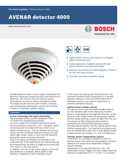
uHighly reliable and accurate thanks to Intelligent Signal Processing (ISP)uEarliest detection of lightest smoke with dual-optical versions (Dual-Ray technology)uMonitors environment for electromagnetic influence for fast root-cause analysisuAutomatic and manual address settingAVENAR detector 4000 is a new range of automatic fire detectors featuring a superb accuracy and swiftness in detection. The versions with two optical sensors (dual‑optical) are able to detect the lightest smoke.The range includes versions with rotaries, manually and automatically addressable, and versions without rotaries for automatic address setting.FunctionsSensor technology and signal processing The individual sensors can be configured in the FSP-5000-RPS programming software.All sensor signals are analysed continuously by the internal evaluation electronics (ISP - Intelligent Signal Processing) and are linked with each other via an inbuilt microprocessor. The link between the sensors means that the combined detectors can also be used where light smoke, steam or dust must be expected during the course of normal operation.Only if the signal combination corresponds to thecharacteristics of the application site, selected during the programming, the alarm is triggered automatically.This results in less false alarms.In addition, the time of the sensor signals on fire and fault detection is analysed, which leads to high detection reliability for each individual sensor.In the case of the optical and chemical sensor, the response threshold (drift compensation) is actively adjusted. Manual or time-controlled switch-off of individual sensors is possible for adjustment to extreme interference factors.Optical sensor (smoke sensor)The optical sensor uses the scattered-light method.An LED transmits light to the measuring chamber,where it is absorbed by the labyrinth structure. In the event of a fire, smoke enters the measuring chamber and the smoke particles scatter the light from the LED.The amount of light hitting the photo diode is converted into a proportional electrical signal.The dual-optical versions use two optical sensors with different wavelengths. The Dual-Ray technology works with an infrared and a blue LED so that lightest smoke is detected fast and reliably (TF1 and TF9 detection).Thermal sensor (temperature sensor)A thermistor in a resistance network is used as athermal sensor from which an analog-digital converter measures the temperature-dependent voltage at regular intervals.Depending on the specified detector class, thetemperature sensor triggers the alarm status when the maximum temperature of 54 °C or 69 °C is exceeded(thermal maximum), or if the temperature rises by a defined amount within a specified time (thermal differential).Chemical sensor (CO gas sensor)The main function of the gas sensor is to detect carbon monoxide (CO) generated as a result of a fire, but it will also detect hydrogen (H) and nitrous monoxide (NO). The sensor signal value is proportional to the concentration of gas. The gas sensor delivers additional information to effectively suppress deceptive values.Since the service life of the gas sensor is limited, the C sensor shuts down automatically after a maximum of 6 years of operation. The detector will then still operate as a multi-sensor detector with dual-optical and thermal sensor. It is recommended to exchange the detector immediately in order to keep the higher detection reliability of the version with C sensor. Improved LSN featuresAVENAR detector 4000 offers all the features of the improved LSN technology:•Flexible network structures, including T‑tappingwithout additional elements (no T-tapping feasible for versions without rotaries)•Up to 254 LSN improved elements per loop or stubline•Automatic or manual detector addressing, with orwithout auto-detection•Power supply for connected elements via LSN bus •Unshielded fire detection cable can be used •Cable length up to 3000 m (with LSN 1500 A)•Backwards compatibility to existing LSN systems and central units•Monitoring of environmental electromagnetic impactfor fast root-cause analysis (EMC values are displayed on the panel)In addition, the range offers all the established benefits of LSN technology. The panel programming software can be used to change the detection characteristics of the respective room utilization. Each configured detector can provide the following data:•Serial number•Contamination level of the optical section •Operating hours•Current analog values–Optical system values: current measured value of the scattered light sensor; the measuring range islinear and shows different degrees of pollution,from slight to heavy.–Contamination: the contamination value shows how much the current contamination value hasincreased relative to the original condition.–CO value: display of the currently measuredvalue.The sensor is self-monitoring. The following errors are indicated on the fire panel:•Fault indication in the event of the failure of thedetector electronics•Continuous display of contamination level duringservice•Fault indication if heavy contamination is detected(instead of triggering a false alarm)In the event of wire interruption or short-circuit,integrated isolators maintain the functional security of the LSN loop.In the event of an alarm, individual detector identification is transmitted to the fire panel.Further characteristics• A red flashing LED visible 360° indicates the alarm.•Connection to a remote indicator is possible.•The strain relief for cables in false ceilings preventsthe cables from being unplugged accidentally fromthe terminals after installation. The terminals forcable cross-sections up to 2.5 mm2 are very easilyaccessible.•The detectors have a dust-repellent labyrinth and cap construction. The chamber maid plug (an openingwith closing plug) on the bottom is used to clean the optical chamber with compressed air (not requiredfor the heat detector).•The detector bases no longer have to be directed due to the centralized position of the individual display.They also have a mechanical removal lock (can beactivated and deactivated).•Connectable to Bosch fire panels with the improved LSN system parameters.•You can use the DO detectors only with the PanelController MPC version B and higher. The PanelController MPC version A cannot be connected.•In LSN classic mode connectable to the LSN firepanels BZ 500 LSN, UEZ 2000 LSN, UGM 2020 and to other panels or their receiver modules with identical connection conditions, although with the previousLSN system parameters•During planning works, it is essential to adhere tonational standards and guidelines.•The detector can be painted (cap and base) andthereby adapted to the surrounding colour scheme.Note the information in the Painting Instructions.•Detectors of the 420 series can be replaced by allversions of the AVENAR detector 4000 without re-configuring the panel.Installation/configuration notes in accordance with VdS/VDE•The FAP‑425-DOTC-R, FAP‑425-DOT-R, FAP‑425-OT-R, and FAP‑425-OT versions are planned in accordance with the guidelines for optical detectors if operatedas optical detectors or as combined optical/thermal detectors (see DIN VDE 0833 Part 2 and VDS 2095)•If occasional deactivation of the optical unit(scattered light sensor) is required, planning must be based on the guidelines for heat detectors (seeDIN VDE 0833 Part 2 and VDS 2095)•When planning fire barriers according to DIBt, notethat the heat detector (FAH-425-T-R) must beconfigured in accordance with class A1R. ElectricalMechanicsEnvironmental conditionsFurther characteristicsLimitsHeed local guidelines. They overrule the following limits.Ordering informationFAP-425-O-R Smoke detector, opticalAnalog addressable detector with one optical sensor, manually and automatically addressable.Order number FAP-425-O-RFAP-425-OT-R Multisensor detector, optical/thermal Analog addressable detector with one optical and one thermal sensor, manually and automatically addressable.Order number FAP-425-OT-RFAH-425-T-R Heat detectorAnalog addressable heat detector with one thermal sensor, manually and automatically addressable. Order number FAH-425-T-RFAP-425-DO-R Smoke detector, dual-opticalAnalog addressable detector with two optical sensors, manually and automatically addressable.Order number FAP-425-DO-RFAP-425-DOT-R Multisensor detector, dual-optic/ther-malAnalog addressable detector with two optical sensors and one thermal sensor, manually and automatically addressable.Order number FAP-425-DOT-RFAP-425-DOTC-R Detector dual-optical/thermal/ chemicalAnalog addressable detector with two optical sensors, one thermal and one chemical sensor, manually and automatically addressable.Order number FAP-425-DOTC-R FAP-425-O Smoke detector, optical auto-addressable Analog addressable detector with one optical sensor, automatic address setting.Order number FAP-425-OFAP-425-OT Detector optic/thermal auto-addressable Analog addressable detector with one optical and one thermal sensor, automatic address setting.Order number FAP-425-OTAccessoriesMS 400 B Detector base with Bosch logoBosch-branded detector base for surface mounted and flush-mounted cable feedOrder number MS 400 BMS 400 Detector baseDetector base for surface mounted and flush-mounted cable feed, not branded.Order number MS 400FAA-420-SEAL Damp room seal, 10 pcsDamp room sealDelivery unit is 10.Order number FAA-420-SEALMSC 420 Base extension with damp room sealing Extension for detector bases with surface-mounted cable feedOrder number MSC 420MS 420 Base with springWith integrated jumper elements for checking the proper wiring during installation.Order number MS 420FAA-MSR420 Detector base with relaywith a change-over relay (Form C)Order number FAA-MSR420FNM-420-A-BS-WH Base sounder indoor, white analog addressable base sounder for indoor use, white, delivered without coverOrder number FNM-420-A-BS-WHFNM-420-A-BS-RD Base sounder indoor, redanalog addressable base sounder for indoor use, red, delivered with coverOrder number FNM-420-A-BS-RDFNM-420U-A-BSWH Base sounder uninterruptible, whiteuninterruptible analog addressable base sounder for indoor use, white, delivered without coverOrder number FNM-420U-A-BSWHFNM-420U-A-BSRD Base sounder uninterruptible in-door, reduninterruptible analog addressable base sounder for indoor use, red, delivered with coverOrder number FNM-420U-A-BSRD FAA-420-RI-DIN Remote indicator for DIN application For applications where the automatic detector is not visible, or mounted in false ceilings/floors.This version complies with DIN 14623.Order number FAA-420-RI-DINFAA-420-RI-ROW Remote indicatorFor applications where the automatic detector is not visible, or mounted in false ceilings/floors.Order number FAA-420-RI-ROWWA400 Wall bracketConsole for DIBt compliant mounting of detectors above doors etc., including detector baseOrder number WA400MH 400 Heating elementusable at locations where the functional safety of the detector might be impaired by condensationOrder number MH 400FMX-DET-MB Mounting bracketMounting bracket for installation in false floorsOrder number FMX-DET-MBSK 400 Protective cageprevents damageOrder number SK 400SSK400 Dust protection, 10pcsProtective dust cover for automatic point type detectors.Delivery unit is 10.Order number SSK400TP4 400 Label plate smallSupport plate for detector identification.Delivery unit is 50.Order number TP4 400TP8 400 Label plate largeSupport plate for detector identification, large. Delivery unit is 50.Order number TP8 400Represented by:Europe, Middle East, Africa:Germany:North America:Asia-Pacific:Bosch Security Systems B.V.P.O. Box 800025600 JB Eindhoven, The Netherlands Phone: + 31 40 2577 284****************************** Bosch Sicherheitssysteme GmbHRobert-Bosch-Ring 585630 GrasbrunnGermanyBosch Security Systems, Inc.130 Perinton ParkwayFairport, New York, 14450, USAPhone: +1 800 289 0096Fax: +1 585 223 9180*******************.comRobert Bosch (SEA) Pte Ltd, Security Systems11 Bishan Street 21Singapore 573943Phone: +65 6571 2808Fax: +65 6571 2699*****************************© Bosch Security Systems 2019 | Data subject to change without notice 136****1419|en,V23,25.Nov2019。
Philips 4000 Series Clock Radio 用户手册说明书

Clock Radio4000 SeriesR4406User manual Register your product and get support at:/supportConnect power 1EN Contents1 Important2Safety222 Your clock radio3Introduction3What's in the box3Overview of the clock radio33 Get started4Install batteries 44Set time44 Listen to FM radio5Tune to FM radio stations Select a preset radio station5Store FM radio stations automatically 55Store FM radio stations manually5Adjust volume55 Other features66 Product information 77 T roubleshooting7Set alarm time6Set sleep timer6Adjust display brightness6Charging device via USB port6FCC information1ImportantSafety• Read these instructions.• Heed all warnings.• Follow all instructions.• Do not block any ventilation openings. Install in accordance with the manufacturer’sinstructions.•Do not install near any heat sources such as radiators, heat registers, stoves, or otherapparatus (including ampli ers) that produce heat.•Protect the power cord from being walked on or pinched, particularly at plugs, convenience receptacles, and the point where they exitfrom the clock radio.Only use attachments/accessories speci ed by the manufacturer.••Unplug this apparatus during lightning storms or when unused for long periods of time.Refer all servicing to quali ed servicepersonnel. Servicing is required when theapparatus has been damaged in any way,such as power-supply cord or plug isdamaged, liquid has been spilled or objects have fallen into the apparatus, the apparatus has been exposed to rain or moisture, doesnot operate normally, or has been dropped. ••Battery usage CAUTION - To prevent battery leakage which may result in bodily injury,property damage, or damage to the clockradio:•Install all batteries correctly, + and - as marked on the unit.•Remove batteries when the unit is not used for a long time.•The battery shall not be exposed toexcessive heat such as sunshine, re or thelike.••This clock radio shall not be exposed to dripping or splashing.•Do not place any sources of danger on the clock radio (e.g. liquid lled objects, lighted candles).Where the plug of the Direct Plug-in Adapter is used as the disconnect device, the disconnect device shall remain readily operable. FCC informationNOTE: This equipment has been tested and• Reorient or relocate the receivingantenna.• Increase the separation between theequipment and receiver.• Connect the equipment into anoutlet on a circuit di erent from thatto which the receiver is connected.• Consult the dealer or an experiencedThis device complies with part 15 of the FCC Rules, Operation is subjuect to the followingtwo conditions: (1) this device may not cause harmful interference, and (2) this device must accept any interference received, including interference that may cause undesired operationradio / TV technician for help.IC-Canada: CAN ICES-3(B)/NMB-3(B)This device contains licence-exempt transmitter(s)/receiver(s) that comply with Innovation, Science and Economic Development Canada’s licence-exempt RSS(s). Operation is subject to the following two conditions:1. This device may not cause interference.2. This device must accept any interference,including interference that may causeundesired operation of the device.found to comply with the limits for a Class B digital device, pursuant to Part 15 of the FCC Rules. These limits are designed to provide reasonable protection against harmful interference in a residential installation. This equipment generates, uses and can radiate radio frequency energy and, if not installed and used in accordance with the instructions, may cause harmful interference to radio communications. However, there is no guarantee that interference will not occur in a particular installation. If this equipment does cause harmful interference to radio or television reception, which can be determined by turning the equipment o and on, the user is encouraged to try to correct the interference by one or more of the following measures:2EN2Your clock radioCongratulations on your purchase, and welcome to Philips! To fully bene t from the support that Philips o ers, register your product at /support.IntroductionWith this clock radio, you can••• listen to FM radio ;What's in the boxCheck and identify the contents of your package:• Main unit• Power adaptor • Quick start guideWarranty• Overview of the clock radio8162347set two alarms to ring at di erent times ; • Turn on or switch to standby.PRESET / SET TIME• Store radio stations in memory.• Select a preset radio station.• Set time.HR / MIN / TUN• Tune to FM radio stations.• Set hour and minute.SNOOZE / BRIGHTNESS• Snooze alarm.• Adjust display brightness.SLEEP / SCAN• Scan and store radio stations automatically.• Set the sleep timer.5Display panel• Display current status.AL1 / AL2 / VOL• Set alarm.• Adjust volume.charge your mobile devices.USB charging port• Charge your mobile devices.4EN3Get startedAlways follow the instructions in this chapter in The batteries can only back up clock and alarm settings.Connect the power adaptor to the wall outlet.sequence.Install batteriesConnect powerInsert 2 AAA batteries (not provided) with correct polarity (+/-) as illustrated.Set time1 In standby mode, press and hold SET TIMEfor 2 seconds.2 Press to select or hour format, then press SET TIME to con rm.3 Press HR to set hour and MIN to setminute, then press to con rm.SET TIME The time is set.TUN< 24Hr >< 12Hr >4Listen to FMradioTune to FM radio stations 1Press to turn on the clock radio.2 Press and hold TUN for 2 seconds.The clock radio tunes to a station withstrong reception automatically.3 Repeat Step 2 to tune to more radio stations. To tune to a station manually:Press TUN repeatedly to select a frequency.Select a preset radio stationIn FM tuner mode, press PRESET repeatedly to select a preset number.Adjust volumeWhile listening, press VOL to adjust volume.Store FM radio stations automatically Store FM radio stations manuallyIn FM tuner mode, press and hold SCAN for more than 2 seconds.The unit stores all the available FM radiostations automatically and broadcasts the rst station.1In FM tuner mode, tune to an FM radio station. 2Press and hold PRESET for 2 seconds to activate programming mode.The preset number begins to blink.3Press TUNTUNrepeatedly to select a number. 4Press again to con rm.PRESET5Repeat steps 1 to 4 to store more FM radio stations.5EN Option A:1 In FM tuner mode, press PRESET.2 Press to select a preset radio station. Option B:TUN6EN5Other featuresSet alarm timeSet alarm1 In standby mode, press and hold AL1 orAL2 for 2 seconds to set alarm time.2 Press HR to set hour and MIN to setto con rm.minute, then press AL1 orAL2Activate/deactivate alarm timerPress AL1 or AL2 repeatedly to activate or deactivate the alarm timer.If the alarm timer is activated, the alarm indicator turns on.If the alarm timer is deactivated, the alarm indicator turns o .The alarm repeats ringing for the next day.To stop the alarm, press the corespondingAL1 or AL2.Snooze the alarmWhen the alarm sounds, press SNOOZE .The alarm snoozes and repeats ringing 9 minutes later.Set sleep timerThis clock radio can switch to standby mode automatically after a preset period.• Press SLEEP repeatedly to select a period (in minutes).The clock radio switches to standby mode automatically after the preset period.To deactivate the sleep timer:Connect the standard size end of a USB cable (not included) to the USB Port on back of the unit and connect the other end to the charging port on your device.• Press SLEEP repeatedly until [OFF ] (o ) appears.Adjust display brightnessCharging device via USB portPress BRIGHTNESS repeatedly to selectdi erent brightness levels:• High • Medium •Low3 Press to select alarm source: buzzer or your last listened FM station, then press AL1 or AL2 again to con rm.7EN 6ProductinformationRated Output Power700mW RMSTuner (FM)Ampli erUSB chargingGeneral informationUSB charging portAC Power (power adaptor)Brand: Philips Model: AS150-Input: 100-240V ~ 50/60 Hz; 0.7A Output: 5V 1.5A 5V 1A(Main unit)224.6 g7TroubleshootingTo keep the warranty valid, never try to repair the device yourself. If you encounter problems when using this device, check the following points before requesting service. If the problem remains unsolved, go to the Philips webpage /support. When you contact Philips, make sure that the device is nearby and the model number and serial number are available.No power• Make sure that the AC power plug of the unitis connected properly.• Make sure that there is power at the AC outlet.No sound• Adjust the volume.No response from the unit• Disconnect and reconnect the AC power plug,then turn on the unit again.Poor radio reception• Keep the clock radio away from otherelectronic devices to avoid radio interference.• Fully extend and adjust the position of theantenna.Alarm does not work• Set the clock/alarm correctly.Clock/alarm setting erased• Power has been interrupted or the powerplug has been disconnected.• Reset the clock/alarm.• Replace the backup batteries.050-AE1502021 © MMD Hong Kong Holding Limited. All rights reserved. Speci cations are subject to change without notice.Philips and the Philips Shield Emblem are registered trademarks of Koninklijke Philips N.V. and are used under license. This product has been manufactured by and is sold under the responsibility of MMD Hong Kong Holding Limited or one of its a liates, and MMD Hong Kong Holding Limited is the warrantor in relation to this product.TAR4406_37_UM_V1.0。
便携式氟利昂R404a检测记录仪(网络版)
便携式氟利昂R404a检测记录仪(网络版)便携式氟利昂R404a检测记录仪的使用方法是开机让便携式氟利昂R404a气体检测仪处于正常工作状态,然后斜挎着便携式氟利昂R404a 气体检测仪表头部分,手拿着抗氧化抗腐蚀的探杆。
移动手中探杆去检测所需要检测环境中的氟利昂R404a气体浓度。
如查找泄漏点,当不知道哪个地方泄漏时,可以拿着仪器去查找泄漏点,浓度最高的地方即为泄漏点。
在结构方面,它是显示表头跟检测探杆分体的一款产品,可像手持那样移动式检测,也可以作为在线产品名称:便携式氟利昂R404a检测记录仪型号:AP-B-C14H18N2O2产品使用环境:产品简介:便携式氟利昂R404a检测记录仪的使用方法是开机让便携式氟利昂R404a气体检测仪处于正常工作状态,然后斜挎着便携式氟利昂R404a气体检测仪表头部分,手拿着抗氧化抗腐蚀的探杆。
移动手中探杆去检测所需要检测环境中的氟利昂R404a气体浓度。
如查找泄漏点,当不知道哪个地方泄漏时,可以拿着仪器去查找泄漏点,浓度最高的地方即为泄漏点。
在结构方面,它是显示表头跟检测探杆分体的一款产品,可像手持那样移动式检测,也可以作为在线式台式检测,更适合一些特定的场所。
便携式氟利昂R404a检测记录仪同样也带有存储记忆功能,可以把你检测过程的每秒数据记录起来方便您后续检测记录数据的查询和接电脑打印。
便携式氟利昂R404a检测记录仪产品特点:●32位高速微处理器。
让数据成立更快、检测更精确。
●彩色液晶中英文双语显示。
彩色显示决定了产品的优美和人性化的显示界面、中英文双语操作系统适合全球各地的客户使用。
●高精度:仪器采用32高速CPU、泵吸式检测、国外知名品牌传感器、先进的电路设计和滤波技术确保了产品的精度。
(1)泵吸式:便携式氟利昂R404a检测记录仪采用泵吸式采集方式。
保证了气腔内气流的稳定性和气压的稳定性,为提高仪器检测的精度做好环境铺垫。
(2)便携式氟利昂R404a检测记录仪采用国际知名品牌气体传感器元件及IC元件:知名品牌元器件在抗干扰性,稳定性方面都是比较好的,这个为提高产品的精度稳定性做好了硬件上的准备。
AH4AL4 选件说明书SD
- 致使用本仪表的人员 -
请妥善保管本使用说明书直至本仪表报废。 另外,请务必记录、保存好设定内容。
产品的保修期间
本仪表的保修期间为自购买日起的1年以内。在保修期内,如果用户遵照使用说明书、产品粘贴标 签等的注意事项正常使用,则一旦产品故障,本公司将免费维修(仅限国内)。届时,请与销售商或本 公司联系。
1.前 言
非常感谢您购买AL4000/AH4000系列(打点式)产品。 本使用说明书只对选件进行了说明。请先充分理解本仪表的使用说明书「综合篇」再阅读本使用说明书。 本使用说明书中说明的选件规格如下。
下位通信 SD 卡数据的重新记录
希望
- 致设计、安装、代理商人员 -
请务必将本使用说明书交于使用本仪表的人员。
8N1
固定为 8N1(8bit/无奇偶校/停止位 1),不可设定
*
-3-
2-3.下位通信(读入)
1.概要
下位通信(读入)是将本仪表作为通信的上位机器,对下位机器的本公司仪表或 PLC 的采集数据进行显 示・记录的功能。可以将采集的数据作为本仪表的输入数据使用。 COM2 接口的通信模式设定为「High(To DB/KP etc…)」后,才可读入下位机器的数据,作为 CH 的数 据进行显示・记录了。
3.SD 卡数据的重新记录................................................................................................................11
3-1.重新记录设定「SDtoPrt」....................................................................................................................12 3-2.执行中画面.....................................................................................................................................键显示菜单画面(设定项目一
AR 电子实验室 RF 仪器 'A' 系列和 'W' 系列的产品介绍说明书
1rf/microwave instrumentation“A ”Series.DC to 400 MHz.25 to 10,000 watts.“W” Series.DC to 1000 MHz.1to 4000 watts.Distributed T ube Amplifier 10 kHz to 100 MHz.10,000 watts.RF Power Amplifiersfor EMC and General RF Testing2009/2010E s t a b l i s h e d 1981AR began in 1969 with just two men in a cellar, moonlighting from their regular jobs.Don (“Shep”) Shepherd and his partner, Dan Roth, worked for AEL (American Electronics Laboratories),producing radio frequency design for military applications. They saw a market for their skills in designing amplifiers for test applications, but AEL was not set up for such jobs. So they decided to try and make it on their own, working out of a makeshift laboratory in Shep’s cellar.1969 – We sold our first amplifier for a total of $600 (including $60 for special connectors).1970 – Moved out of Shep’s cellar and up to small rented storefront. 1972 – Distribution expands into Europe.1973 – Amplifier Research (AR) moves to new headquarters at160 School House Rd. in Souderton, PA.1976 – AR introduces first 10,000 watt tube amplifier (10 kHz -100 MHz). It’s still available,and there’s still no equal.1979 – Company passes $1 million in sales.1987 – 75 employees now work for AR.1988 – First 100 watt solid-state, 100-1000 MHzinstantaneous bandwidth amplifier built.It weighed 215 lbs. and was 29.3" high.1990 – Second building completed at headquarters. Sales exceed $10 million.1992 – AR unveils first 500 watt solid-state amplifier (100 -1000 MHz).1994 – A third building is erected at 160 School House Rd.1996 – AR reaches $25 million in sales with 100 employees.2001 – The company expands it capabilities into amplifier modulesand customized systems with the acquisition of Kalmus in Bothell, WA, now AR Modular RF .Back in Souderton, a fourth building is completed. Sales exceed $35 million.“We started the company in my basement.Because the only place we could go from there was up.”Don Shepherd, Founder2002 – Carnel Labs in Canoga Park, CA joins the AR family,becoming AR Receiver Systems.2003 – First 10,000 watt / 100 kHz - 250 MHz solid-state amplifier forautomotive/military/avionics testing created. Still the only 10,000 watt solid state available.2004 –The little company that started in a cellar now has 125 employees.2005 – New engineering department and microelectronics lab (clean room) open.Sales pass the $45 million mark.2006 – New 15,000 sq. ft. building is completed at corporate headquarters withexpanded production facilities to meet the ever-growing demand for AR products.150 employees now work for AR.2007– AR introduces first 10-20 GHz / 5 watt instantaneous bandwidth test amplifier.2009– AR celebrates 40 years in business.AR, which now encompasses AR RF/Microwave Instrumentation, AR Modular RF ,AR Receiver Systems and AR Europe, employs over 200 people and continues to lead the industry with innovative, superior quality, technologically-advanced products and a global support system that’s second to none.We definitely have risen far from Shep’s cellar.21Folding back is typical of Class AB and lesser-grade Class A designs. AR’s Class A circuitry is built to higher standards:All “Class A”Is Not The Same.• AR uses tandem push-pull transistor pairs. This arrangement is more rugged than the single output devices found in lesser grade Class A amplifiers.• AR amplifiers use internal power combiners that can withstand high reflected power.• AR amplifiers use only top quality, high-power internal directional couplers • AR amplifiers use switching power supplies to increase efficiency and reduce internal heat load.It’s no wonder that only AR claims and delivers 100% rated power to the load!“We Started With A Dream,And It’s Grown Into A Reality.”T oday we’re recognized as the ultimate source for testing and communications solutions in the worlds of EMC,military, wireless, and beyond. And our products are everywhere.They’re boosting the power of military radios for our troops in battle; driving the most sophisticated industrial/medical/scientific equipment; testing the emissions and susceptibility of electronic equipment; and helping new electronic products get to market faster.We’ve become the industry leader by continually setting the bar a little higher.By raising quality.And increasing cost-efficiency.With innovations like “subampability” – the ability to add power to existing amps; and test systems that can be upgraded from the Internet to adapt to changing specs.With the combined resources of all the AR companies, AR is your source for everything from RF power amplifiers,antennas, complete test systems, probes, monitors, software and receivers to military booster amps, and RF amplifier modules that can be customized to meet the toughest specs.We take great pride in the support & service we deliver to our customers anywhere in the world, whenever they need it.Infinite VSWR T olerance Means More P ower T o Y ou.Approximately 80% of the amplifiers in this brochure are completely immune to load VSWR. That means 100% of the power is delivered to the load 100% of the time. Our highest power amplifiers refuse to limit until VSWR exceeds 6.0:1 or 50% (of rated output) reflected power. Competitive Class AB amplifiers respond to reflected power from high VSWR by limiting output power at the exact time you need every bit of power. Some actually shut down. We find that completely unacceptable .Donald “Shep” Shepherd Chairman430The Difference Is Power Delivered T o The Load.Since the output power of AR amplifiers does not fold back with VSWR, more power is absorbed in the load.The Difference Is Several Times Greater.Most AR amplifiers do not fold back or limit. The power absorbed by the load is many times greater than with competitive amplifiers that fold back at 1/VSWR.and one controller/combiner, you get 3000watts of power;and so on up to 4000 watts.The amplifiers can still be used independently when tests call for less power.See Application Note #40A Expandable Power for further details.W e design our amplifiers not just for today, but for tomorrow. Most models include:• Digital Control Panels (DCP) in one of two formats: graphical vacuum fluorescent or two-line vacuum fluorescent• Built-in IEEE-488 Interface and RS-232interface (Fiberoptic RS-232 on Graphical DC • Local and Remote Control (on DCP amplifier)• Forward and Reflected Power Readout (on graphical DCPs)• Control Status and Internal Amplifier Status Reports• USB and Ethernet – on selected models See individual amplifier spec sheets to verify the features on any amplifier.Expandable PowerRF test levels are constantly increasing. The same is true for many test distances. Usually, this requires larger, more powerful amplifiers. It also means throwing out your old amps. But AR is changing all that.Many amplifiers in our “S” and “W” Series allow you to add power to existing amps as needed. There’s no need to toss out a perfectly good amp and start all over again. W e call this concept “Subampability .”Much like building blocks, it enables you to add incremental power using existing amps. With arelatively simple upgrade, you can “combine” multiple amps to achieve the power you need. This is clearly an idea whose time has come.But it gets even better.Since the higher power would be needed only for some tests, “Subampability” enables you to split the amplifiers so that they can be used individually whenever needed.Here’s an example of how “Subampability” works: If you start with a 1000W1000C amplifier (1000 Watts CW , 80-100 MHz) and then you need more power,you can add another 1000W1000C amplifier and a controller/combiner for 2000 watts of power.And you can keep going!With three 1000W1000C amplifiersGood Enough Isn’t Good Enough.So W e Keep T weaking.Ready For The Future.Subampability™: (sub-amp-ability). noun: The ability to use an amplifier individually , or as a building block, upon which powercan be added incrementally .Solid State, Low Frequency Amplifiers.W e’re constantly under the cover of our amplifierstweaking the major components and making improvements. After years of R&D, AR has perfected the technology of optimal module performance. The result is increased bandwidth and more power, especially at the high end of the frequency range.T wo modules, one from 100 kHz to 250 MHz and one from 100 kHz to 400 MHz, offer this new technology. These modules serve as basic building blocks for the 10,000A250A and 5000A250Aamplifiers, as well as for the 100A400 and 150A400amplifiers for BCI applications.The need for higher power is continually increasing; and AR is ready. Our new “A” Series amplifiers feature 500, 1000, and 2500-watt models with expanded coverage down to 10 kHz.And we’re now able to pack more power into smaller “packages.”6AR Competitive Edge products supply a multitude of unique RF solutions to companies around the world. The company’s limitless support network reaches the far corners of the globe. AR products are backed by the company’s“Competitive Edge” warranty, the best and most comprehensive warranty in the industry.When companies purchase from any AR company they have the peace of mind that comes from knowing the global leader will be there to help with any problems today, tomorrow and always.A Global Support Network That’s Second T o None.A warranty is only as good as the company and the people behind it. AR’s highly-trained,experienced support staff is the best in the business.And they are right where you need them, in all the far corners of the globe. Help is just a phone call away… today, tomorrow and always.See “Sales Associates” at for a complete listing or call Customer Service at 215-723-0275.By the way, when you call,you’ll talk to a real receptionist who will connect you to the help you need. Y ou can also call our hotline at 800-933-8181 and talk to directly an applications engineer whose job is to help one person at a time.V alue Right From The Start… a 10% Bonus.AR’s quality makes our products a good value.But we also help you save right up front. When you visit the AR booth at a trade show, you’ll receive a bonus coupon that’s worth 10% of the purchase price of your AR amplifier toward the purchase of any AR accessory. That’s anything other than amplifiers–and it’s good for up to $20,000!Quality, V alue, Service and Innovation That No Other Company Can Match.With the combined resources of all the AR companies, AR is your source for everything from power amplifiers, antennas, complete test systems,probes, monitors, software and receivers to amplifier modules that can be customizedto meet the toughest specs.5The Most Comprehensive And Most Meaningful W arranty In The Industry.A Better Amplifier And A Better V alue. W att For W att, Our Amplifiers Cost Less!Lower cost doesn’t necessarily equal a better value.Not when you’re paying for power that you never get.The following equation will help you calculate the per-watt cost of your amplifier and the dollar-for-dollar value:Consider a typical 100 watt AR Class A amplifier driving a high VSWR (100 watt output, 50% or 50 watts reflected at 6.0:1 and 50 watts absorbed by the load) at a cost of $20,000–Compare this with a competitive 100 watt Class AB amplifier also driving a high VSWR (due to foldback, only 34 watts output, 50% or 17 watts reflected at 6.0:1 and 17 watts absorbed by the load) at a cost of $15,000–These numbers clearly demonstrate that while the initial cost of AR amplifiers may be higher, the net result based on superior performance is greater value. In other words, our amplifiers provide more bang for the buck!$20,00050W= $400/watt$15,00017W= $882/wattAmplifier PricePower Absorbed by the Load= Amplifier Price Per Watt40AD140 watts CW. dc-1 MHz.Rated Output Power40 watts Input For Rated Output 1.0 milliwatt max.350AH1350 watts CW. 10 Hz - 1 MHz.Operation Class AB LinearPower Output(1.79 Ohm load)75A40075 watts CW. 10 kHz-400 MHz.Rated Output Power75 watts min.Input For Rated Output 1.0 milliwatt max.1500A31500 watts CW. 10 kHz-3 MHz.Rated Output Power1500 wattsInput For Rated Output 1.0 milliwatt max.5000A35000 watts CW. 10 kHz-3 MHz.Rated Output Power5000 wattsInput For Rated Output 1.0 milliwatt max.800A3A800 watts CW. 10 kHz-3 MHz.Rated Output Power800 wattsInput For Rated Output 1.0 milliwatt max.25A250A25 watts CW. 10 kHz-250 MHz. Rated Output Power25 watts Input For Rated Output 1.0 milliwatt max.75A250A75 watts CW. 10 kHz-250 MHz.Rated Output Power75 wattsInput For Rated Output 1.0 milliwatt max.100A250A100 watts CW. 10 kHz-250 MHz.Rated Output Power100 wattsInput For Rated Output 1.0 milliwatt max.500A250A500 watts CW. 10 kHz-250 MHz.Rated Output Power500 wattsInput For Rated Output 1.0 milliwatt max.1000A2251000 watts CW. 10 kHz-225 MHz.Rated Output Power1000 wattsInput For Rated Output 1.0 milliwatt max.2500A2252500 watts CW. 10 kHz-225 MHz.Rated Output Power2500 watts, 10 kHz - 50 MHz2500 - 1900 watts, 50 MHz - 225 MHz150A100B150 watts CW . 10 kHz-100 MHz.Rated Output Power 150 watts Input For Rated Output 1.0 milliwatt max.150A220150 watts CW . 10 kHz-220 MHz.Rated Output Power 150 watts min.Input For Rated Output 1.0 milliwatt max.3500A100A3500 watts CW .10 kHz-100 MHz.Rated Output Power 3500 watts Input For Rated Output 1.0 milliwatt max.10,000L10,000watts CW .10 kHz-100MHz.Rated Output Power Nominal 12,600 watts 100A400100 watts CW . 100 kHz-400 MHz.Rated Output Power 100 watts min.Input For Rated Output 1.0 milliwatt max.150A400150 watts CW . 100 kHz-400 MHz.Rated Output Power 150 watts min.Input For Rated Output 1.0 milliwatt max.5000A250A5000 watts CW.100 kHz-250MHz. Rated Output Power5000 watts, 100 kHz - 100 MHz5000 - 3000 watts, 100 MHz - 250 MHz Input For Rated Output 1.0 milliwatt max.10000A250A10,000watts CW.100kHz-250MHz.Rated Output Power10,000 watts, 100 kHz - 100 MHz10,000 - 6,000 watts, 100 MHz - 250 MHz1W1000B1 watt CW. 100 kHz-1000 MHz.Rated Output Power 1.0 watts min.Input For Rated Output 1.0 milliwatt max.10W1000C10 watts CW. 500 kHz-1000 MHz.Rated Output Power10 watts min.Input For Rated Output 1.0 milliwatt max.30W1000B30 watts CW. 1-1000 MHz.Rated Output Power30 watts min.Input For Rated Output 1.0 milliwatt max.150A250150 watts CW. 100 kHz-250 MHz. Rated Output Power150 watts min. Input For Rated Output 1.0 milliwatt max.250W1000A250 watts CW. 80-1000 MHz. Rated Output Power250 watts min. Input For Rated Output 1.0 milliwatt max.500W1000A500 watts CW. 80-1000 MHz.Rated Output Power525 watts min.Input For Rated Output 1.0 milliwatt max.1000W1000C1000 watts CW. 80-1000 MHz.Rated Output Power1000 watts min.Input For Rated Output 1.0 milliwatt max.100W1000B100 watts CW. 1-1000 MHz. Rated Output Power100 watts Input For Rated Output 1.0 milliwatt max.150W1000150 watts CW. 80-1000 MHz. Rated Output Power150 watts Input For Rated Output 1.0 milliwatt max.50W1000B50 watts CW. 1-1000 MHz. Rated Output Power50 watts min. Input For Rated Output 1.0 milliwatt max.3000W10003000 watts CW. 80-1000 MHz. Rated Output Power2800 watts min. Input For Rated Output 1.0 milliwatts max.4000W10004000 watts CW. 80-1000 MHz.Rated Output Power3600 watts min.Input For Rated Output 1.0 milliwatts max.10WD100010 watts CW. dc-1000 MHz.Rated Output Power15 watts min.Input For Rated Output 1.0 milliwatt max.50WD100050 watts CW. dc-1000 MHz.Rated Output Power50 watts min.Input For Rated Output 1.0 milliwatt max.2000W1000A2000 watts CW. 80-1000 MHz. Rated Output Power1900 watts min. Input For Rated Output 1.0 milliwatts max.40AD1– DC - 1 MHz1000W1000C – 80 MHz - 1 GHz250W1000A – 80 MHz - 1 GHz350AH1 – 10 Hz - 1 MHz150A400 – 100 kHz - 400 MHz150A250– 100 kHz - 250 MHz150A220 – 10 kHz - 220 MHz100A250A – 10 kHz - 250 MHz50WD1000– DC - 1 GHz50W1000B – 1 MHz - 1 GHz30W1000B – 1 MHz - 1 GHz10WD1000– DC - 1 GHz10W1000C – 500 kHz - 1 GHz1W1000B – 100 kHz - 1 GHz25A250A 10 kHz - 250 MHz75A250A – 10 kHz - 250 MHz500A250A –10 kHz - 250 MHz150W1000 – 80 MHz - 1 GHz 500W1000A – 80 MHz - 1 GHz800A3A – 10 kHz -3 MHz1500A3 – 10 kHz -3 MHz1000A225 – 10 kHz - 225 MHz2000W1000A – 80 MHz - 1 GHz2500A225 – 10 kHz - 225 MHz3000W1000 – 80 MHz - 1 GHz3500A100A –10 kHz - 100 MHz4000W1000 – 80 MHz - 1 GHz5000A250A – 100 kHz - 250 MHz5000A3 – 10 kHz -3 MHz10,000A250A – 100 kHz - 250 MHz10,000L – 10 kHz - 100 MHz75A400– 10 kHz - 400 MHz100W1000B – 1 MHz - 1 GHz150A100B – 10 kHz - 100 MHzO U T P U T P O W E R (W A T T S )11010253040505075751001001001501501501501502503505005008001k 1k 1.5k 2k 2.5k 3k 3.5k 4k 5k 5k 10k 10k15801002003004005006007008009001000500100FREQUENCYFREQUENCY1920100A400 – 100 kHz - 400 MHza r RF/Microwave Instrumentationa r Modular RFa r Receiver Systemsa rEuropea rrf/microwave instrumentation •modular rf •receiver systems •ar europe© Copyright 2009 AR AR5694–7.5Ma rRF/Microwave Instrumentationa rModular RFa r Receiver Systemsa rEurope。
4000系列数字便携式分析仪使用说明书
Instruction Manual 4000 Series Digital Portable AnalyzerService Department(800) 458-6153 ext. 121(818) 882-2331 ext. 121FAX(818)341-0642E-mail:************************THIS P AGE INTENTIONALL Y LEFT BLANKTABLE OF CONTENTSSECTION TITLE PAGE1.0 Equipment DescriptionFront Panel 4Rear Panel 6Right Side Panel 7Internal components 8 2.0 Operating InstructionsSetting the Alarm 9Zeroing the Instrument 10Sampling 11 3.0 CalibrationIntroduction 12Sample Bag & Pressurized Cylinder Calibration 14Calibration Procedure 15 4.0 General MaintenanceBattery Life 16Battery Charging & Replacement 16Water loss in Refillable Sensors 18Long Term Storage 23Post Storage Startup 235.0 Troubleshooting 246.0 Warranty 257.0 Return Authorization 268.0 AppendixINTERFERING GAS DATA 27SCRUBBER INFORMATION 31Note:It is not necessary to calibrate the monitor whenreceived from the Interscan or an authorized distributor.All Interscan monitors are calibrated at the factory prior toshipment.The Interscan 4000 Digital series operates on the principle of pullinga sample (Sample draw) through a sensor. The Electrochemicalsensor is manufactured by Interscan. Electrochemical means thatit produces an electrical current proportional to the level of gaspassing through. The large size of the Interscan sensors results inlarger reactive surface area which yields greater sensitivity. Equipment Description(fig. 1)Designation FunctionLCD Display:Indicates gas level when function switch is inZERO, SAMPLE INACTIVE or SAMPLEACTIVE, and battery level when on BAT.TEST A or B.ALARM Light:LED. Flashes ON/OFF when alarm setpoint is exceeded.ALARM SET:25-Turn potentiometer with a screwdriveradjustment. Sets the alarm trip point at thedesired gas level. (low alarm set must begreater than 5% of the full scale).SPAN/CAL:25-Turn potentiometer with a screwdriveradjustment. Sets display to correspond to theconcentration of the calibration gas used forcalibrating the instrument or to the levelspecified on ECS certificate.FUNCTION SWITCH:Rotary switch as follows:OFF:Analyzer power is OFF.SAMPLEINACTIVE:Analyzer power is ON (pump is OFF),Sampling is inactive.SAMPLEACTIVE:Analyzer power and pump are on. Also in thisposition the analyzer is zeroed. Samplemeasurements and calibration areaccomplished in the sample mode.BAT.TEST A:Indicates state of charge of the Nickel-Cadmium (NiCd) batteries on the LCDDisplay. These batteries power the pump &alarm. Recharge if the LCD Display level fallsto or below 100 (ignore decimal point).BAT. TEST B:Indicates state of charge of the “C” sizealkaline batteries on the LCD Display. Thesebatteries power the main circuitry, display andare NOT re-chargeable. Replace if the LCDDisplay level falls to or below 100 (ignoredecimal point). You must allow an overnightstabilize prior to use if the batteries arereplaced. Batteries are to be checkedevery 30 days.ZERO:10-Turn Potentiometer. Allows the meter to beadjusted to zero, by compensating for anybackground signal.(fig. 2)Designation FunctionINLET:¼” O.D. Quick connect or compression gasfitting.OUTLET:¼” O.D. Quick connect or compression gasfitting.RECORDER OUTPUT:¼” phone jack for Analog recorder outputconnection. Typically 0-100mV. Tip –positive, Ring – ground.CHARGER INPUT: 3.5mm phone jack for 9V DC, 100mA chargerinput. Tip – positive, Ring – ground.SENSOR SCREWS:Used to hold Sensor or Sensor base in place.(fig. 3)AUDIBLE ALARM:Piezoelectric Horn, sounds when alarm setpoint is exceeded.The above (fig 3) page 7, #12 indicates two #1 Phillips-head screws located on the right side panel. Removing these screws allows access to the internal components. Do not remove any other screws(fig. 4)Operating InstructionsNormally, the alarm is set at the Factory at 50% of full scale. Thealarm can be reset to any desired level by following the procedurebelow. Minimum alarm level must be greater than 5% of the fullscale measuring range.Set FUNCTION switch to SAMPLE INACTIVE. Using the ZEROcontrol, advance the LCD display to the desired alarm set point.Some analyzers require the use of span tool (provided). Adjust theALARM SET (fig. 1 pg. 4)control until the alarm sounds. Adjust theZERO control slightly counterclockwise until the alarm is silent. Toconfirm setting slowly adjust the ZERO control clockwise until thealarm sounds. Re-adjust the ALARM SET control if necessary.Adjust the ZERO control for a reading of “0” on the display.The Analyzer must always be zeroed, prior to use.Zero adjustments must be made in the SAMPLE ACTIVE mode,i.e. with the pump on, in air free of interfering gases. If necessary,use zero air or a C-12 filter (provided) to zero in the sampling area.When using C-12 zero filter, connect externally to gas inlet. Allowreading to stabilize, before making final zero adjustment,(stabilization can take approximately 20 minutes). The C-12 filtermust be removed after zeroing the analyzer.Analyzer must be zeroed prior to sampling (section 2.1).Set the FUNCTION switch to SAMPLE ACTIVE to activate the pump. If the INLET or OUTLET is blocked, the pump may stall. Note: Running the Analyzer with blocked INLET or OUTLET may lead to the sensor leaking caustic electrolyte leading toanalyzer damage.Power analyzer off, and clear the blockage. To reset the pump, set the FUNCTION switch to SAMPLE INACTIVE momentarily and then switch again to SAMPLE ACTIVE.Nominal sample rate in MOST analyzers is approximately 1.0, ±0.2 liter per minute. NOTE: For hydrazine analyzers with the measuring range of 0-100ppb the sample flow rate is 2.2 ± 0.2 liters per minute.The Average sample run time, starting with fully charged “C” NiCd batteries, is 12 hours. If the BATTERY TEST “A” indication is down to 100 on the LCD display, the flow rate may have started to decrease. This is usually not a problem unless very precise readings are required.Sampling from high pressure may only be achieved by using the method indicated in (fig. 5).Note: The sample to the Interscan Analyzer must be drawn perpendicular to the Sample flow stream.(fig. 5)CalibrationAll analyzers are factory calibrated prior to shipment.There is no easy answer as to how often a monitor should becalibrated. This is strictly a function of the application (gasconcentration and frequency of exposure to target gas). Thepurpose for calibration is to compensate for any possible decreasein sensor sensitivity. The primary cause of sensitivity decrease isexcessive loss of water by evaporation. A secondary cause maybe by contamination from unknown sources. H2S sensors show anadditional decrease in sensitivity due to internal sulfur formation, therate of which depends on the gas concentration.Interscan’s SENSOR EXPRESS® program streamlines downtimeby sending you a pre-calibrated sensors on a regular basis per yourneeds, without the burden of returning sensors to our factory for re-certification. The sensors are shipped to you either twice , threetimes, or four times per year at your discretion.Follow the instructions received with the Sensor, allow to stabilize,and the instrument is ready for use. The factory recommendedprocedure for calibrating all INTERSCAN analyzers, involves theuse of certified calibration gas or a permeation device. Besidesbeing essential for calibration, having a known certified gasstandard on hand allows the user to test the analyzer at any time todetermine that it “really works”As indicated on the certification sheet, the Sensor Express®. It doesnot certify the analyzer as a whole. Most importantly, the SensorExpress® program is not a substitute for basic analyzermaintenance, nor does it check for malfunction of the analyzercomponents.Whatever the source of calibration gas, the recommended method is to collect the gas in the proper sample bag, which is then attached to the analyzer INLET. The calibration gas is drawn from the proper sample bag through the sensor. An exception to the use of a sample bag is for those gases, which are reactive with, or chemisorbed by the bag itself (e.g. Chlorine, Hydrazine). Teflon® or Tedlar® bags are suitable for H2S, SO2, NO and NO2. Several bag materials are suitable for CO. Contact the Factory for recommendations.The sample bag method is the factory-recommended method for calibration. Since an internal pump is used, the same flow rate conditions during the sample and the calibrate modes are assured, eliminating errors due to flow rate differences. For most applications, using a bag is the simplest procedure.A regulated pressurized certified cylinder fitted with a tee-manifold (fig. 6) and unrestricted vent is a good procedure in place of the sample bag, as long as the flow rate of the gas is at least 140 percent that of the sample pump.(fig. 6)Analyzer must be zeroed prior to calibration (sec 2.1).1. For all gases, except Chlorine or other chemisorbable types, fill the 5 litersample bag with calibration gas, and attach it to the external inlet fitting.This is best done by attaching a short length 4 inch (101.6mm) of 1/4 inch(6.35 mm) O.D. Teflon tubing to the sample bag, then inserting into theinlet fitting.2. Set the FUNCTION switch to SAMPLE ACTIVE.3. Allow 2 to 3 minutes for the reading to stabilize, and by using theSPAN/CAL control, set the display to match the calibration gas concentration being used.4. Remove the sample bag from the analyzer and allow the display tostabilize.5. The analyzer is now calibrated and set up for operation.NOTE: If you require additional information on Calibrationprocedures, please contact the Service Department at 1-800-458-******************************************General MaintenanceBecause of current requirements of the circuitry, “C” size alkalinebattery life should be check on a monthly basis, whether the unit isoperating or not. Note: Batteries vary in capacity bymanufacturer and may provide more battery life. Analyzermalfunction, as a result of low battery, will be evident as eitherinability to zero the monitor or clipping of the display at a fixedreading below full scale.Nickel-cadmium battery life is indeterminate. It is somewhatdependent upon how well the charge level is maintained.All models of the 4000 Series analyzers use two “C” size alkalinebatteries. These are located on the hinged door, right side (fig. 4 pg.8). Polarity is marked on the door over the battery holder.A few minutes warm-up/stabilization is needed before using theanalyzer if alkaline batteries are replaced before Battery Test “B”indicates a low battery condition (100). Replace “C” alkalinebatteries and allow monitor to stabilize overnight if the batteries arelow or dead. The FUNCTION switch should be set to OFF duringthis time. This is performed to allow the sensor time to stabilize.The rechargeable batteries are ½ “C” size NiCd and are rated at0.80 ampere hours. They are mounted on the hinged door, left side(fig. 4 pg. 8). Polarity is marked on the door, over the battery holder.All models use four ½ cell “C” size NiCd batteries. Condition isshown in the BATTERY TEST “A”, FUNCTION switch position. TheNiCd battery voltage changes quite rapidly as it approaches therecharge point, which makes accurate display indication difficult. Itis recommended that the batteries be recharged if the reading inBATTERY TEST “A” is at 100 (ignoring the decimal place). Allowingthe reading to drop below 100 is not recommended. Note: NiCd batteries can develop cell memory. Cell memory is caused by running the analyzer on battery power for a short period of time REPEATEDLY i.e: Running the analyzer for 20 minutes and then recharge. If this occurs repeatedly, the NiCd battery life will only retain a 20 minute charge memory.The charger is an external 9V DC, 500mA transformer and is connected to the rear of the unit prior to charging. The tip is positive and the ring ground. The FUNCTION switch should be set to OFF or SAMPLE INACTIVE when charging. The recommended charge time is 16 hours.(fig. 7)All sensors provided with a fill port require that the electrolyte matrix is maintained in a near-saturated condition in order to provide optimum performance. This is achieved by injecting distilled or deionized water into the sensor via the red plug, using the plastic syringe (provided).Refer to (fig. 7 pg. 16). Refillable sensors are identified by the red fill plug in the side of the sensor. The fill plug location may vary from(fig. 7 pg. 16). There are two types of refillable sensors. The S-type is a shorter sensor of slightly over 2 1/2 inches ( 64 mm) in height; the P-type is almost 4 inches (104 mm) in height. “P” and “S” type sensors connect to the analyzer by different connection methods.For portable survey monitors, the sensor should be removed and weighed every 1 to 2 months, depending upon usage. The weight loss is indicated on the weight label on the side of the sensor. Sensor weight is restored be removing the sensor from the analyzer and comparing the current weight of the sensor with its original weight (in grams). Sensor weight is indicated on a label located on the side of the sensor.There are three types of gas fittings used depending on the age of the original sensor and the gas being measured.(fig. 8)Male elbow ¼ O.D. tube compression fittingThis is a compression fitting comprised of the body, nut and two ferrules (fig. 8). Disconnect by loosening the nut until the tubing can be pulled away from the body. To re-attach insert the tubing and tighten the nut. Do NOT over tighten the nut as this will damage the nut and fitting(fig. 9)Quick connect male elbowThis is a quick connect system comprised of the body, o-ring and ferrule (fig. 9). Disconnect by pushing on the ring where the tubing enters the fitting and gently pulling on the tubing. Re-attach by inserting the tubing all the way in and then gently pull backward.(fig. 10)Barbed male elbowThe fitting uses a barbed connector system (fig. 10). Disconnect by pulling on the tubing. Re-attach by pushing the tubing onto the fitting until firmly seated.Fig. 11For P-type sensors refer to (fig. 11). Disconnect the 2 electrical connections to the sensor. Disconnect the tubing from each gas fitting. Loosen the screw indicated as “A”. Loosen the clamp screw “B” until the sensor can be removed from clamp.NOTE: DO NOT REMOVE ANYTHING ELSERestore the sensor to within 5 grams original sensor weight by injecting an equivalent cc of distilled or deionized water (10g. weight loss means add 10cc water). DO NOT OVERFILL. If sensor will not take on any more liquid (liquid starts coming out the fill port) do not attempt to add additional distilled water.Note: Weight loss in excess per sensor weight label may prevent the restoration of the weight to within 5 grams of the original weight.DO NOT OVERFILL. After weighing and refilling replace the sensor in the analyzer, tighten screw “B” taking care only to make it tight so as to secure the sensor. Then tighten screw “A”, do not over tighten.Assure that all electrical and pneumatic fittings are secure. The sensor should be allowed to stabilize forseveral hours with power off.(fig. 12)For S-type sensors refer to (fig. 12). Disconnect the two electrical connections to the sensor. Disconnect the tubing from each gas fitting. Remove the two Sensor Screws (# 7).NOTE: DO NOT REMOVE ANYTHING ELSE!!Restore the sensor to within 5 grams original sensor weight by injecting an equivalent cc of distilled or deionized water (10g. weight loss means add 10cc water). DO NOT OVERFILL. If sensor will not take on any more liquid (liquid starts coming out the fill port) do notattempt to add additional distilled water.Note: Weight loss in excess per sensor weight label may prevent the restoration of the weight to within 5 grams of the original weight.DO NOT OVERFILL. After weighing and refilling replace the sensor in the analyzer, tighten screws on the rear of the analyzer. Assure that all electrical and pneumatic fittings are secure. The sensor should be allowed to stabilize for several hours with power off.Turn FUNCTION swit ch to “OFF” position. Disconnect charger from analyzer. Detach 15 pin “D” connector from circuit board. Remove alkaline batteries and cover analyzer to protect from dust.24 Hours Before Using:Uncover the analyzer. Install FRESH alkaline batteries. Reconnect 15-pin “D” connector from circuit board. Connect the charger to the analyzer to charge NiCd batteries.After 24 Hours:Follow instructions in Section 2.0. Analyzer is ready to use or calibrate.WarrantyINTERSCAN CORPORATION warrants portable analyzers of itsmanufacture (sensors, batteries, fuses, lamps, tubing, fittings,filters, and scrubbers excepted) to be free from defects in materialand workmanship for a period of one year from date of shipment.INTERSCAN CORPORATION warrants sensors of its manufactureto be free from defects in material and workmanship for a period ofsix months from date of shipment.INTERSCAN CORPORATION'S sole obligation under thiswarranty is limited to repairing or replacing, at its option, any itemcovered under this warranty, when such item is returned intact,prepaid to the factory (or designated service center).This warranty does not apply to any of our products which havebeen repaired or altered by unauthorized persons, or which havebeen subject to misuse, negligence, or accident, incorrect wiring byothers, installation or use not in accordance with instructionsfurnished by the manufacturer, or which have had the serialnumbers altered, effaced or removed. The sensors are factorysealed and must not be opened or modified in the field for thewarranty to remain in effect. This warranty is in lieu of all otherwarranties, whether expressed or implied.Additionally, in a custom system, warranty on any component shallnot exceed the manufacturer's warranty given to INTERSCANCORPORATION.Return AuthorizationAll returns for repairs require a "RETURN AUTHORIZATIONNUMBER" issued by the INTERSCAN Service Department uponrequest. Below is the link to the RMA form:/contact/index.phpThis is done primarily to cause the user to contact the factorydirectly. The reason for this is that a high percentage of serviceproblems are resolved over the telephone, avoiding the need forreturning the analyzer or part.Should return of the analyzer or part be advised by the ServiceDepartment, the "RETURN AUTHORIZATION NUMBER" willexpedite prompt return of the repaired unit.For service information, please contact:INTERSCAN CORPORATIONService Department(800) 458-6153 ext. 121(818) 882-2331 ext. 121FAX(818)341-0642E-mail:************************Appendix AINTERFERING GAS DATANo analytical method is completely specific. Gases present in the environment, other than the "target" gas of measurement, may affect analyzer response. Interferences are not necessarily linear, and may also exhibit time dependent characteristics.The charts that follow detail the approximate concentration in parts per million of interfering gas required to cause a 1 ppm deflection in the chosen analyzer. In many cases, specificity can be improved. Please note that the response values given are not absolute, and may vary depending on sensor formulation.The special case of how alcohols affect electrochemical sensors is discussed in this Knowledge Base article. ()For further information on the effects of interfering gases, please contact the factory.The charts follow the format, and grouping of gases, that was originally established in early Interscan print brochures.Chart 1: CO, Cl2, ClO2, H2, H2S, NO, NO2, O3, SO2 analyzersChart 2: Ethylene oxide (EtO) (C2H4O) analyzersChart 3: Formaldehyde (HCHO) analyzersChart 4: HCl, HCN, hydrazine analyzersChart 5: C2H4 (ethylene) analyzers(1) Data shown for H 2S models with ranges higher than 0-1999 ppb (2) Data shown for H 2S models with ranges of 0-1999 ppb and lower‡ = Hydrocarbons¤ = Rejection ratio can be improved electronically¶ Isopropyl alcohol represents the most significant interference on the ethylene oxide sensor, but in nearly all cases, potential problems can be overcome. Typical remedial actions include:a. Point shutdown/automatic restart, which allows the operator to temporarily interrupt monitoring at points that could be affected when isopropyl alcohol is used. Monitoring restarts automatically on a time-adjustable basis.b. Selection of monitoring points away from those areas that may be unduly affected by isopropyl alcohol.c. Using alternative germicides, which do not contain isopropyl alcohol.The EtO sensor may also respond to strong odors of colognes and perfumes, and to certain floor strippers and waxes. Refer to guidelines above covering isopropyl alcohol. Remember that you are attempting to monitor parts per million levels of ethylene oxide in an environment that may contain percent (10,000 ppm = 1 percent) levels of these potentially interfering compounds.= Negative interference= Negative interference § = Scrubber available= Negative interference= Negative interferenceAppendix B SCRUBBER INFORMATION。
- 1、下载文档前请自行甄别文档内容的完整性,平台不提供额外的编辑、内容补充、找答案等附加服务。
- 2、"仅部分预览"的文档,不可在线预览部分如存在完整性等问题,可反馈申请退款(可完整预览的文档不适用该条件!)。
- 3、如文档侵犯您的权益,请联系客服反馈,我们会尽快为您处理(人工客服工作时间:9:00-18:30)。
II
前言
本说明书使用的标志说明
标志 名称 危险 警示 含义 若不采取适当的预防措施,将导致严重的人身伤害、仪表损坏或重大财产损失等事 故。 提醒您对产品有关的重要信息或本说明书的特别部分格外注意。 请谨慎进行该项操作,执行错误可能导致重大问题。 请仔细阅读此项注释,对正确操作仪表有很大帮助。
!
警告 注意
第 2 章 选型代码 ................................................................................................................................................ 4 2.1 AR3000/AR4000 经典记录仪 ............................................................................................................... 4 2.2 AR3100/AR4100 运算记录仪 ............................................................................................................... 4 第 3 章 按键和菜单 ............................................................................................................................................ 6 3.1 面板部件 ................................................................................................................................................ 6 3.2 按键操作 ................................................................................................................................................ 7 3.2.1 监控画面切换................................................................................................................................ 7 3.2.2 组态登录........................................................................................................................................ 9 3.2.3 关于信息查看................................................................................................................................ 9 3.2.4 菜单导航...................................................................................................................................... 10 3.2.5 参数类型和设置方法 .................................................................................................................. 11 第 4 章 仪表基本信息设置 .............................................................................................................................. 14 4.1 基本设置 .............................................................................................................................................. 14 4.1.1 基本设置组态步骤 ...................................................................................................................... 14 4.1.2 基本设置参数介绍 ...................................................................................................................... 14 4.2 用户设置 .............................................................................................................................................. 15 4.3 监控画面组态 ...................................................................................................................................... 15 4.4 组态管理 .............................................................................................................................................. 16 4.5 启用组态 .............................................................................................................................................. 17 4.6 快捷菜单操作 ...................................................................................................................................... 17 4.7 状态栏基本信息介绍 .......................................................................................................................... 18 4.7.1 监控画面状态栏 .......................................................................................................................... 18 4.7.2 组态画面状态栏 .......................................................................................................................... 18 第 5 章 输入输出 .............................................................................................................................................. 19 5.1 模拟量输入通道 AI ............................................................................................................................. 19 5.1.1 AI 组态步骤 ................................................................................................................................ 19 5.1.2 AI 参数介绍 ................................................................................................................................ 20 5.2 开关量输入通道 DI ............................................................................................................................. 25 5.2.1 DI 组态步骤 ................................................................................................................................ 25 5.2.2 DI 参数介绍 ................................................................................................................................ 25 5.3 脉冲量输入通道 PI .............................................................................................................................. 26 5.3.1 PI 组态步骤 ................................................................................................................................. 26 5.3.2 PI 参数介绍 ................................................................................................................................. 26 5.4 模拟量输出通道 AO............................................................................................................................ 27 5.4.1 AO 组态步骤 ............................................................................................................................... 27 5.4.2 AO 参数介绍 ............................................................................................................................... 27 5.5 开关量输出通道 DO............................................................................................................................ 28 5.5.1 DO 组态步骤 ............................................................................................................................... 28 5.5.2 DO 参数介绍 ............................................................................................................................... 28 5.6 输入输出相关监控画面 ...................................................................................................................... 28 5.6.1 输入输出总貌画面 ...................................................................................................................... 28