rfc2429.RTP Payload Format for the 1998 Version of ITU-T Rec. H.263 Video (H.263+)
基于IE浏览器H.264视频播放插件的实现
插件的实现.计算机应用研究,2005,22(4):152—154.
万方数据
Practical Experience实践经验1 63
基于IE浏览器H.264视频播放插件的实现
作者: 作者单位: 刊名:
英文刊名: 年,卷(期): 被引用次数:
刘晓梅, 王彦永, 魏立峰, 王庆辉 沈阳化工学院,信息工程学院,辽宁,沈阳,110142
程间通信。编译生成H264PLAYER.OCX文件后,用
VC提供的测试容器ActiveX Test Container即可测
试这个控件。
4 H.264视频播放插件实现
插件就是一个框架中的处理单元,输入进插件的 一个或多个媒体流,经过插件对数据进行处理并将结 果输出。利用插件式框架设计方法,可以把流媒体系 统分成多个模块。在本实现中,利用ActiveX技术, 通过多线程通信和高效的数据传递机制实现了H.264 流媒体播放插件的设计。
ActiveX控件能通过设置属性控制其行为,从
①基金项目:辽宁省教育厅高等学校科技公关计划项目(20040291):沈阳市科技项目应用基础研究计划项目(1081236-卜00) 收稿时间:2008-07-1 9
万方数据
Practical Experience实践经验161
计算机系统应用
2009年第3期
6结束语 本文实现了H.264视频播放插件设计。通过lE
浏览器对该插件的加载,可以看到视频测试序列 carphone—qcif.yuv在IE浏览器中的播放效果如图4 所示:
圈4视频测试结果
测试结果表明,此视频播放插件可以接收并播放 来自网络的经H.264标准压缩的RTP流,播放速率 约1 5帧/秒,可应用于低码率视频通信。在后续工作 中需要进一步增加和完善插件功能,并对软件进行优 化。此插件的设计为视频电话、视频会议、视频监控 及远程教育等软件的开发提供了重要参考。
RFC1889协议中文概要

RFC1889 协议中文概要摘要这份文档描述了 RTP 这份实时传输协议。
RTP 提供了端到端的传输功能, 通过 多播或者单播的方式, 适合于传输如音频、 视频等实时数据。
RTP 并不保证服务质 量, 也没有提供资源预留。
传输的数据通过控制协议 RTCP 的补充来实现乃至大 规模多播传输方式下的监视功能。
并通过 RTCP 提供一些控制和识别流的功能。
RTP 和 RTCP 被设计成独立于传输和网络层。
这份协议支持使用 RTP 层的混流 服务器(MIXER)和译流服务器(TRANSLATOR)。
1.介绍RTP 通常和 UDP ,同时也可以和其他协议共用来实现传输实时数据, 如果下层 网络允许的话,支持目的地为多个地址的多播传输。
RTP 原先被设计用于多方参加的多媒体味议,但也可以用于如交互摹拟等其他 应用。
对于特定的应用, RTP 协议是可扩展的。
所以 RTP 协议只是一个框架, 并且有 意被定义为如此。
在实际应用时, RTP 协议的包头可以被修改来得到所需的功能, 而不是像传统协议那样靠不断修改并使其统一来变得更完善。
1.配置文档(profile specification document ) 定义传输负载类型编码和与实际负载类型格式的对应关系。
对于特定的应用, 还定义了对于 RTP 所应做的扩展和修改。
2.负载格式规范文档(payload format specification documents ) 定义了特定格式编码的音、视频文件如何在 RTP 协议中传输。
2.一些 RTP 应用实例2.1 简单的音频会议通过 IP 多播方式建立的一个会议, 每一个参预者通过某些分配机制 (不在本协议 讨论范围中)得到一个组地址和 2 个端口号,一个端口号用来传送 RTP 数据, 即音频数据, 另一个用来传输 RTCP 控制数据。
如果需要加密,可根据本协议第正因为上述原因,使用 RTP 协议时,普通需要两种伴有文档: RTP 并不保证服务质量而主要靠下层协议的支持,所以每一个包都有一个顺序号 使接受方能按序重建数据。
(完整word版)RTP传DTMF(RFC2833)

摘要:本文主要说明采用RFC2833标准进行DTMF传送的方法和格式。
关键字:RFC2833,RTP,DTMF一、IP电话传送DTMF的方式DTMF就是双音多频,我们日常生活中拨打电话的过程中经常会用到,如拨打用户的分机号码,输入帐号和密码等。
而随着IP电话的大量使用如何实现传送DTMF成为IP电话中的一个技术问题。
目前传送DTMF信号普遍有两种方式:带内传送和带外传送。
其中带外传送主要通过将DTMF消息封装到协议中进行传送,如H323协议中可以通过Q931和H245进行传送DTMF。
而带内传输主要有两种:透明传送和RFC2833方式。
所谓透明传送就是将DTMF音作为语音一起打包到RTP中进行发送。
由于网络丢包的影响,有时会造成DTMF信号丢失,而且DTMF音混合在语音包中,容易产生偏差,造成信号失真。
所以目前普遍采用的是RFC2833方式,就是将DTMF数字按照一个的规则和格式组成一个数据包,然后封装到RTP中发送。
接收端接收后进行解析,再还原成相应的DTMF信号,这种方式的优点是对丢包的容错性强以及识别差错率低。
二、RTP在介绍RFC2833前,先来了解一下RTP(Real Time Protocal),该协议可参见RFC1889。
RTP协议是IP电话中以及NGN中最经典的协议。
无论采用H323,H248,MGCP还是SIP,这些都属于信令层的协议,他们之间进行互通、交换其最终目的是为了实现媒体流的收发。
而所有的媒体流都是采用RTP协议,无论是视频,语音还是图象,包括本文所提到的DTMF都是建立在RTP的基础上的。
RTP协议用以传送实时数据.RTP协议通常运行在UDP层之上,二者共同完成运输层的功能。
UDP提供复用及校验和服务,也就是通过分配不同的端口号传送多个RTP流。
协议规定,RTP流使用偶数(2n)端口号,相应的RTCP流使用相邻的奇数(2n+1)端口号。
因此,应用进程应在一对端口上接收RTP数据和RTCP控制数据,同时向另一对端口上接收RTP数据和RTCP控制数据。
浙江大华DH650平台设备接入协议

DH650平台设备接入协议1.概述DH650平台设备接入协议(后面简称本协议)描述DH650平台的设备接入协议,规定了设备接入DH650平台进行通信时的命令和数据交互的细节。
本协议引用到的相关规范:z IETF RFC 2616: "Hypertext Transfer Protocol – HTTP/1.1", Fielding R. et al., June 1999.z"Extensible Markup Language (XML) 1.0 Specification (Second Edition)", T. Bray, J. Paoli, C. M. Sperberg-McQueen, E. Maler, 6 October 2000.z IETF RFC 2326: "Real Time Streaming Protocol (RTSP)", Schulzrinne H., Rao A. and Lanphier R., April 1998.z IETF RFC 2327: "SDP: Session Description Protocol", Handley M., Jacobson V. and Perkins C., April 1998.z IETF RFC 3550: "RTP: A Transport Protocol for Real-Time Applications", Schulzrinne H. et al., January 1996.z IETF RFC 3016: "RTP Payload Format for MPEG-4 Audio/Visual Streams", Kikuchi Y. et al., November 2000.z IETF RFC 3984: "RTP Payload Format for H.264 Video", Wenger S. et al, February 2005.2.协议整体设计2.1. 通讯协议组成通讯协议由一个命令通道和零到多个数据通道组成。
中移动家庭网关终端技术规范v

中移动家庭网关终端技术规范vThe document was finally revised on 2021中国移动通信企业标准QB-╳╳-╳╳╳-╳╳╳╳家庭网关终端技术规范T e c h n i c a l S p e c i f i c a t i o n f o r H o m e版本号:╳╳╳╳-╳╳-╳╳发布╳╳╳╳-╳╳-╳╳实施中国移动通信集团公司发布目录前言本标准明确了中国移动家庭网关需求,是家庭网关终端需要遵从的技术文件。
供中国移动内部和厂商共同使用,是实施家庭业务的依据之一。
本标准主要包括以下几方面内容:接口要求、功能要求、性能要求、网管和维护要求、软硬件系统要求以及运行环境等要求。
本标准是家庭网关设备系列标准之一,该系列标准的结构、名称或预计的名称如下:本标准需与《家庭网关业务技术规范》、《家庭网关业务技术规范—WLAN 共享分册》、《宜居通业务技术规范》、《家庭宽带类业务技术规范》、《家庭网关管理技术规范》、《宜居通终端技术规范》配套使用。
本标准的附录A、附录B为标准性附录。
本标准由中移号文件印发。
本标准由中国移动通信集团公司数据部提出,集团公司技术部归口。
本标准起草单位:中国移动通信研究院本标准主要起草人:张勇浩、梅海波、李建坤、刘聪、郭毅峰、陈心昕、黄薇、周丹、殷端、张彪、杨彦、刘松鹏、封栋梁、金波、叶朝阳1.范围本标准规定了中国移动家庭网关的设备形态、接口、功能、管理、安全、性能、运行环境、设备软硬件、基本应用和用户界面等要求,供中国移动通信集团内部使用,是开发研制接入型和宽带应用型家庭网关的技术依据。
本标准适用于2G/3G/4G移动网络、有线宽带网络环境。
2.规范性引用文件下列文件中的条款通过本标准的引用而成为本标准的条款。
凡是注日期的引用文件,其随后所有的修改单(不包括勘误的内容)或修订版均不适用于本标准,然而,鼓励根据本标准达成协议的各方研究是否可使用这些文件的最新版本。
AAC以adts格式封装的分析
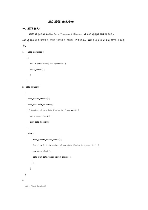
AAC ADTS 格式分析一、ADTS格式:ADTS的全称是Audio Data Transport Stream。
是AAC音频的传输流格式。
AAC音频格式在MPEG-2(ISO-13318-7 2003)中有定义。
AAC后来又被采用到MPEG-4标准中。
1. adts_sequence(){while (nextbits() == syncword) {adts_frame();}}2. adts_frame(){adts_fixed_header();adts_variable_header();if (number_of_raw_data_blocks_in_frame == 0) {adts_error_check();raw_data_block();}else {adts_header_error_check();for (i = 0; i <= number_of_raw_data_blocks_in_frame; i++) {raw_data_block();adts_raw_data_block_error_check();}}}3.adts_fixed_header(){syncword; 12 bslbfID; 1 bslbflayer; 2 uimsbfprotection_absent; 1 bslbfprofile; 2 uimsbfsampling_frequency_index; 4 uimsbfprivate_bit; 1 bslbfchannel_configuration; 3 uimsbforiginal/copy; 1 bslbfhome; 1 bslbf}adts_variable_header(){copyright_identification_bit; 1 bslbfcopyright_identification_start; 1 bslbfframe_length; 13 bslbfadts_buffer_fullness; 11 bslbfnumber_of_raw_data_blocks_in_frame; 2 uimsfb}详细说明下ADTS头的重要数据部分:syncword 同步字The bit string ‘1111 1111 1111’,说明一个ADTS帧的开始。
264视频的RTP荷载格式H26...
rfc3984 H.264视频的RTP荷载格式H.264视频的RTP荷载格式Status of This MemoThis document specifies an Internet standards track protocol for theInternet community, and requests discussion and suggestions forimprovements. Please refer to the current edition of the "InternetOfficial Protocol Standards" (STD 1) for the standardization stateand status of this protocol. Distribution of this memo is unlimited.Copyright NoticeCopyright (C) The Internet Society (2005).AbstractThis memo describes an RTP Payload format for the ITU-TRecommendation H.264 video codec and the technically identicalISO/IEC International Standard 14496-10 video codec. The RTP payloadformat allows for packetization of one or more Network AbstractionLayer Units (NALUs), produced by an H.264 video encoder, ineach RTPpayload. The payload format has wide applicability, as it supportsapplications from simple low bit-rate conversational usage, toInternet video streaming with interleaved transmission, to high bit-rate video-on-demand.目录1. 介绍 (3)1.1. H.264 Codec (3)1.2. 参数集概念 (4)1.3. 网络抽象层单元类型 (5)2. 约定 (6)3. 范围 (6)4. 定义和缩写 (6)4.1. 定义 (6)5. RTP 荷载格式 (8)5.1. RTP 头的使用 (8)5.2. RTP荷载格式的公共使用 (11)5.3. NAL单言字节的用法 (12)5.4. 打包方式 (14)5.5. 解码顺序号 (DON) (15)5.6. 单个NAL单元包 (18)5.7. 复合包 (18)5.8. 分片单元 (FUs) (27)6. 分包规则 (31)6.1. 公共分包规则 (31)6.2. 单个NAL单元方式 (32)6.3. 非交错方式 (32)6.4. 交错方式 (33)7. 打包过程 (信息) (33)7.1. 单NAL单元和非交错方式 (33)7.2. 交错方式 (34)7.3. 附加的打包原则 ..................368. 荷载格式参数 (37)8.1. MIME 注册 (37)8.2. SDP 参数 (52)8.3. 例子 (58)8.4. 参数集考虑 (60)9. 安全考虑 (62)10. 拥塞控制 (63)11. IANA考虑 (64)12. 信息化附录: 应用例子 (65)12.1. 根据ITU-T H.241 附录A的视频电话 (65)12.2. 没有分片数据分区,没有NAL单元聚合的视频电话 (65)12.3. 使用NAL单元聚合交错打包的视频电话 (66)12.4. 使用数据分区的视频电话 (66)12.5. 使用FU和向前纠错的视频电话和流 (67)12.6. 低位率流 (69)12.7. 视频流中健壮的包调度 (70)13. 信息化附录:解码顺序号的原理 (71)13.1. 介绍 (71)13.2. 多图像片断交错的例子 (71)13.3. 健壮包调度的例子 (73)13.4. 冗余编码片断健壮传输调度的例子 (77)13.5. 其它设计可能的提醒 (77)14. 致谢 (78)15. 参考 (78)15.1. 标准化参考 (78)15.2. 参考性的参考 (79)作者地址 (81)完全版权声明 (83)1. 介绍1.1. H.264 Codec本文指定一个RTP荷载规范用于ITU-T H.264 视频编码标准(ISO/IEC 14496 Part 10 [2])(两个都称为高级视频编码AVC). H.264建议在2005年5月被ITU-T采纳, 草案规范对于公共回顾可用[8]. 本文H.264 缩写用于codec和标准,但是本文等价于采纳 ISO/IEC相似的编码标准.H.264 视频 codec又非常广泛的应用覆盖所有格式的数字压缩视频格式,从低带宽的Internet流应用到HDTV广播和数字影院应用。
AMR编解码格式介绍
每一帧的数据有分为三个部分:Class A/B/C
Class A:一帧中最敏感、最重要的数据。一旦这一部份数据有损坏,整个帧就无法解码,就损坏了。所以,一般在无线传输的时候要使用各种冗余的方式对这部分数据加以保护。
-
-
二、AMR帧格式:
AMR有两种类型的帧格式:AMR IF1和AMR IF2
1. AMR IF1:
IF1的帧格式如下图所示:
FrameType, Mode Indication, Mode Request对应上面两个表格里的数。从上面的表格里我们可以看出,这三个域的值是相同的。所以在IF2中省略了Mode Indication, Mode Request两个域。
图3列举了AMR-NB 5.9Kbit的一个帧的格式,
对于5.9kbit一帧的有118bit的数据,15*8=120=118+2,所以在最后有2个bit的填充位。
参考文献:
RFC3267 RTP Payload Format for AMR and AMR-WB
3GPP TS 26.201 V6.0.0
4
1
253
6
33
3
AMR-WB 14.25 kbit/s
4
1
285
6
37
4
AMR-WB 15.85 kbit/s
4
1
317
6
41
5
AMR-WB 18.25 kbit/s
4
1
365
6
47
6
AMR-WB 19.85 kbit/s
RTSP协议开发接口说明(2012)
以上方法都是交互过程中最为常用的。
二.几种传输方式
1.RTP OVER UDP
(1)用户在 SETUP 阶段发送一个 SETUP 命令,trackID=1。只能取得视频。 (2)用户在 SETUP 阶段发送一个 SETUP 命令,trackID=2。只能取得语音。 (3)用户在 SETUP 阶段发送两个 SETUP 命令,trackID=1,trackID=2。能够取得视频和语 音。
Transport: RTP/AVP;unicast;client_port=1094-1095;server_port=12028-12029
RTSP PLAY,该命令为客户端启动数据传输,需要并产生下列头部字段:
Range
规定播放的范围。因为只支持实时流,所以只有开始时间没有结 束时间。
RTP-Info 关于 RTP 流的信息,包含下一个 RTP 序列号 C-S:PLAY rtsp://192.0.1.100/Streaming/Channels/101 RTSP/1.0
如果在会话的头部包含 timeout 参数, kept alive 超时后,会话将自动关闭。Kept alive 是通过 RTSP_GET_PARAMETER,RTSP_SET_PARAMETER,RTSP_OPTIONS 来实现的实 现的。
C-S:SETUP rtsp://192.0.1.100/Streaming/Channels/101/trackID=1 RTSP/1.0
1389957320
Range: npt=nowRTP-Info: url=trackID=1;seq=29626 //seq 是 rtp 包中的信息
RTP包格式详细解析
RTP包格式详细解析H.264 视频 RTP 负载格式1. ⽹络抽象层单元类型 (NALU)NALU 头由⼀个字节组成, 它的语法如下:+---------------+|0|1|2|3|4|5|6|7|+-+-+-+-+-+-+-+-+|F|NRI| Type |+---------------+F: 1 个⽐特.forbidden_zero_bit. 在 H.264 规范中规定了这⼀位必须为 0.NRI: 2 个⽐特.nal_ref_idc. 取 00 ~ 11, 似乎指⽰这个 NALU 的重要性, 如 00 的 NALU 解码器可以丢弃它⽽不影响图像的回放. 不过⼀般情况下不太关⼼这个属性.Type: 5 个⽐特.nal_unit_type. 这个 NALU 单元的类型. 简述如下:0 没有定义1-23 NAL单元单个 NAL 单元包.24 STAP-A 单⼀时间的组合包25 STAP-B 单⼀时间的组合包26 MTAP16 多个时间的组合包27 MTAP24 多个时间的组合包28 FU-A 分⽚的单元29 FU-B 分⽚的单元30-31 没有定义2. 打包模式下⾯是 RFC 3550 中规定的 RTP 头的结构.0 1 2 30 1 2 3 4 5 6 7 8 9 0 1 2 3 4 5 6 7 8 9 0 1 2 3 4 5 6 7 8 9 0 1+-+-+-+-+-+-+-+-+-+-+-+-+-+-+-+-+-+-+-+-+-+-+-+-+-+-+-+-+-+-+-+-+|V=2|P|X| CC |M| PT | sequence number |+-+-+-+-+-+-+-+-+-+-+-+-+-+-+-+-+-+-+-+-+-+-+-+-+-+-+-+-+-+-+-+-+| timestamp |+-+-+-+-+-+-+-+-+-+-+-+-+-+-+-+-+-+-+-+-+-+-+-+-+-+-+-+-+-+-+-+-+| synchronization source (SSRC) identifier |+=+=+=+=+=+=+=+=+=+=+=+=+=+=+=+=+=+=+=+=+=+=+=+=+=+=+=+=+=+=+=+=+| contributing source (CSRC) identifiers || .... |+-+-+-+-+-+-+-+-+-+-+-+-+-+-+-+-+-+-+-+-+-+-+-+-+-+-+-+-+-+-+-+-+负载类型 Payload type (PT): 7 bits序列号 Sequence number (SN): 16 bits时间戳 Timestamp: 32 bitsH.264 Payload 格式定义了三种不同的基本的负载(Payload)结构. 接收端可能通过 RTP Payload的第⼀个字节来识别它们. 这⼀个字节类似 NALU 头的格式, ⽽这个头结构的 NAL 单元类型字段则指出了代表的是哪⼀种结构,这个字节的结构如下, 可以看出它和 H.264 的 NALU 头结构是⼀样的.+---------------+|0|1|2|3|4|5|6|7|+-+-+-+-+-+-+-+-+|F|NRI| Type |+---------------+字段 Type: 这个 RTP payload 中 NAL 单元的类型. 这个字段和 H.264 中类型字段的区别是, 当 type的值为 24 ~ 31 表⽰这是⼀个特别格式的 NAL 单元, ⽽ H.264 中, 只取 1~23 是有效的值.24 STAP-A 单⼀时间的组合包25 STAP-B 单⼀时间的组合包26 MTAP16 多个时间的组合包27 MTAP24 多个时间的组合包28 FU-A 分⽚的单元29 FU-B 分⽚的单元30-31 没有定义可能的结构类型分别有:1. 单⼀ NAL 单元模式即⼀个 RTP 包仅由⼀个完整的 NALU 组成. 这种情况下 RTP NAL 头类型字段和原始的 H.264的NALU 头类型字段是⼀样的.2. 组合封包模式即可能是由多个 NAL 单元组成⼀个 RTP 包. 分别有4种组合⽅式: STAP-A, STAP-B, MTAP16, MTAP24.那么这⾥的类型值分别是 24, 25, 26 以及 27.3. 分⽚封包模式⽤于把⼀个 NALU 单元封装成多个 RTP 包. 存在两种类型 FU-A 和 FU-B. 类型值分别是 28 和 29.2.1 单⼀ NAL 单元模式对于 NALU 的长度⼩于 MTU ⼤⼩的包, ⼀般采⽤单⼀ NAL 单元模式.对于⼀个原始的 H.264 NALU 单元常由 [Start Code] [NALU Header] [NALU Payload] 三部分组成, 其中 Start Code ⽤于标⽰这是⼀个NALU 单元的开始, 必须是 "00 00 00 01" 或 "00 00 01", NALU 头仅⼀个字节, 其后都是 NALU 单元内容.打包时去除 "00 00 01" 或 "00 00 00 01" 的开始码, 把其他数据封包的 RTP 包即可.0 1 2 30 1 2 3 4 5 6 7 8 9 0 1 2 3 4 5 6 7 8 9 0 1 2 3 4 5 6 7 8 9 0 1+-+-+-+-+-+-+-+-+-+-+-+-+-+-+-+-+-+-+-+-+-+-+-+-+-+-+-+-+-+-+-+-+|F|NRI| type | |+-+-+-+-+-+-+-+-+ || || Bytes 2..n of a Single NAL unit || || +-+-+-+-+-+-+-+-+-+-+-+-+-+-+-+-+| :...OPTIONAL RTP padding |+-+-+-+-+-+-+-+-+-+-+-+-+-+-+-+-+-+-+-+-+-+-+-+-+-+-+-+-+-+-+-+-+如有⼀个 H.264 的 NALU 是这样的:[00 00 00 01 67 42 A0 1E 23 56 0E 2F ... ]这是⼀个序列参数集 NAL 单元. [00 00 00 01] 是四个字节的开始码, 67 是 NALU 头, 42 开始的数据是 NALU 内容.封装成 RTP 包将如下:[ RTP Header ] [ 67 42 A0 1E 23 56 0E 2F ]即只要去掉 4 个字节的开始码就可以了.2.2 组合封包模式其次, 当 NALU 的长度特别⼩时, 可以把⼏个 NALU 单元封在⼀个 RTP 包中.0 1 2 30 1 2 3 4 5 6 7 8 9 0 1 2 3 4 5 6 7 8 9 0 1 2 3 4 5 6 7 8 9 0 1+-+-+-+-+-+-+-+-+-+-+-+-+-+-+-+-+-+-+-+-+-+-+-+-+-+-+-+-+-+-+-+-+| RTP Header |+-+-+-+-+-+-+-+-+-+-+-+-+-+-+-+-+-+-+-+-+-+-+-+-+-+-+-+-+-+-+-+-+|STAP-A NAL HDR | NALU 1 Size | NALU 1 HDR |+-+-+-+-+-+-+-+-+-+-+-+-+-+-+-+-+-+-+-+-+-+-+-+-+-+-+-+-+-+-+-+-+| NALU 1 Data |: :+ +-+-+-+-+-+-+-+-+-+-+-+-+-+-+-+-+-+-+-+-+-+-+-+-+| | NALU 2 Size | NALU 2 HDR |+-+-+-+-+-+-+-+-+-+-+-+-+-+-+-+-+-+-+-+-+-+-+-+-+-+-+-+-+-+-+-+-+| NALU 2 Data |: :| +-+-+-+-+-+-+-+-+-+-+-+-+-+-+-+-+| :...OPTIONAL RTP padding |+-+-+-+-+-+-+-+-+-+-+-+-+-+-+-+-+-+-+-+-+-+-+-+-+-+-+-+-+-+-+-+-+2.3 Fragmentation Units (FUs).⽽当 NALU 的长度超过 MTU 时, 就必须对 NALU 单元进⾏分⽚封包. 也称为 Fragmentation Units (FUs).0 1 2 30 1 2 3 4 5 6 7 8 9 0 1 2 3 4 5 6 7 8 9 0 1 2 3 4 5 6 7 8 9 0 1+-+-+-+-+-+-+-+-+-+-+-+-+-+-+-+-+-+-+-+-+-+-+-+-+-+-+-+-+-+-+-+-+| FU indicator | FU header | |+-+-+-+-+-+-+-+-+-+-+-+-+-+-+-+-+ || || FU payload || || +-+-+-+-+-+-+-+-+-+-+-+-+-+-+-+-+| :...OPTIONAL RTP padding |+-+-+-+-+-+-+-+-+-+-+-+-+-+-+-+-+-+-+-+-+-+-+-+-+-+-+-+-+-+-+-+-+Figure 14. RTP payload format for FU-AThe FU indicator octet has the following format:+---------------+|0|1|2|3|4|5|6|7|+-+-+-+-+-+-+-+-+|F|NRI| Type |+---------------+The FU header has the following format:+---------------+|0|1|2|3|4|5|6|7|+-+-+-+-+-+-+-+-+|S|E|R| Type |+---------------+3. SDP 参数下⾯描述了如何在 SDP 中表⽰⼀个 H.264 流:. "m=" ⾏中的媒体名必须是 "video". "a=rtpmap" ⾏中的编码名称必须是 "H264".. "a=rtpmap" ⾏中的时钟频率必须是 90000.. 其他参数都包括在 "a=fmtp" ⾏中.如:m=video 49170 RTP/AVP 98a=rtpmap:98 H264/90000a=fmtp:98 profile-level-id=42A01E; sprop-parameter-sets=Z0IACpZTBYmI,aMljiA==下⾯介绍⼀些常⽤的参数.3.1 packetization-mode:表⽰⽀持的封包模式.当 packetization-mode 的值为 0 时或不存在时, 必须使⽤单⼀ NALU 单元模式.当 packetization-mode 的值为 1 时必须使⽤⾮交错(non-interleaved)封包模式.当 packetization-mode 的值为 2 时必须使⽤交错(interleaved)封包模式.这个参数不可以取其他的值.3.2 sprop-parameter-sets:这个参数可以⽤于传输 H.264 的序列参数集和图像参数 NAL 单元. 这个参数的值采⽤ Base64 进⾏编码. 不同的参数集间⽤","号隔开.3.3 profile-level-id:这个参数⽤于指⽰ H.264 流的 profile 类型和级别. 由 Base16(⼗六进制) 表⽰的 3 个字节. 第⼀个字节表⽰ H.264 的 Profile 类型, 第三个字节表⽰ H.264 的 Profile 级别:3.4 max-mbps:这个参数的值是⼀个整型, 指出了每⼀秒最⼤的宏块处理速度.re: H.264 RTP payload 格式 2009-12-25 17:17 heshui⾟苦啦。
- 1、下载文档前请自行甄别文档内容的完整性,平台不提供额外的编辑、内容补充、找答案等附加服务。
- 2、"仅部分预览"的文档,不可在线预览部分如存在完整性等问题,可反馈申请退款(可完整预览的文档不适用该条件!)。
- 3、如文档侵犯您的权益,请联系客服反馈,我们会尽快为您处理(人工客服工作时间:9:00-18:30)。
Network Working GroupRequest for Comments: 2429 C. Bormann Category: Standards Track Univ. Bremen L. Cline G. Deisher T. GardosC. MacioccoD. Newell Intel J. Ott Univ. Bremen G. Sullivan PictureTel S. Wenger TU Berlin C. Zhu Intel October 1998 RTP Payload Format for the 1998 Version ofITU-T Rec. H.263 Video (H.263+)Status of this MemoThis document specifies an Internet standards track protocol for the Internet community, and requests discussion and suggestions forimprovements. Please refer to the current edition of the "InternetOfficial Protocol Standards" (STD 1) for the standardization stateand status of this protocol. Distribution of this memo is unlimited. Copyright NoticeCopyright (C) The Internet Society (1998). All Rights Reserved.1. IntroductionThis document specifies an RTP payload header format applicable tothe transmission of video streams generated based on the 1998 version of ITU-T Recommendation H.263 [4]. Because the 1998 version of H.263 is a superset of the 1996 syntax, this format can also be used withthe 1996 version of H.263 [3], and is recommended for this use by new implementations. This format does not replace RFC 2190, whichcontinues to be used by existing implementations, and may be required for backward compatibility in new implementations. Implementationsusing the new features of the 1998 version of H.263 shall use theformat described in this document.Bormann, et. al. Standards Track [Page 1]The 1998 version of ITU-T Recommendation H.263 added numerous coding options to improve codec performance over the 1996 version. The 1998 version is referred to as H.263+ in this document. Among the newoptions, the ones with the biggest impact on the RTP payloadspecification and the error resilience of the video content are theslice structured mode, the independent segment decoding mode, thereference picture selection mode, and the scalability mode. Thissection summarizes the impact of these new coding options onpacketization. Refer to [4] for more information on coding options. The slice structured mode was added to H.263+ for three purposes: to provide enhanced error resilience capability, to make the bitstreammore amenable to use with an underlying packet transport such as RTP, and to minimize video delay. The slice structured mode supportsfragmentation at macroblock boundaries.With the independent segment decoding (ISD) option, a video pictureframe is broken into segments and encoded in such a way that eachsegment is independently decodable. Utilizing ISD in a lossy network environment helps to prevent the propagation of errors from onesegment of the picture to others.The reference picture selection mode allows the use of an olderreference picture rather than the one immediately preceding thecurrent picture. Usually, the last transmitted frame is implicitlyused as the reference picture for inter-frame prediction. If thereference picture selection mode is used, the data stream carriesinformation on what reference frame should be used, indicated by the temporal reference as an ID for that reference frame. The reference picture selection mode can be used with or without a back channel,which provides information to the encoder about the internal statusof the decoder. However, no special provision is made herein forcarrying back channel information.H.263+ also includes bitstream scalability as an optional codingmode. Three kinds of scalability are defined: temporal, signal-to-noise ratio (SNR), and spatial scalability. Temporal scalability is achieved via the disposable nature of bi-directionally predictedframes, or B-frames. (A low-delay form of temporal scalability known as P-picture temporal scalability can also be achieved by using thereference picture selection mode described in the previousparagraph.) SNR scalability permits refinement of encoded videoframes, thereby improving the quality (or SNR). Spatial scalability is similar to SNR scalability except the refinement layer is twicethe size of the base layer in the horizontal dimension, verticaldimension, or both.Bormann, et. al. Standards Track [Page 2]2. Usage of RTPWhen transmitting H.263+ video streams over the Internet, the output of the encoder can be packetized directly. All the bits resultingfrom the bitstream including the fixed length codes and variablelength codes will be included in the packet, with the only exception being that when the payload of a packet begins with a Picture, GOB,Slice, EOS, or EOSBS start code, the first two (all-zero) bytes ofthe start code are removed and replaced by setting an indicator bitin the payload header.For H.263+ bitstreams coded with temporal, spatial, or SNRscalability, each layer may be transported to a different networkaddress. More specifically, each layer may use a unique IP addressand port number combination. The temporal relations between layersshall be expressed using the RTP timestamp so that they can besynchronized at the receiving ends in multicast or unicastapplications.The H.263+ video stream will be carried as payload data within RTPpackets. A new H.263+ payload header is defined in section 4. This section defines the usage of the RTP fixed header and H.263+ videopacket structure.2.1 RTP Header UsageEach RTP packet starts with a fixed RTP header. The following fields of the RTP fixed header are used for H.263+ video streams:Marker bit (M bit): The Marker bit of the RTP header is set to 1 when the current packet carries the end of current frame, and is 0otherwise.Payload Type (PT): The Payload Type shall specify the H.263+ videopayload format.Timestamp: The RTP Timestamp encodes the sampling instance of thefirst video frame data contained in the RTP data packet. The RTPtimestamp shall be the same on successive packets if a video frameoccupies more than one packet. In a multilayer scenario, allpictures corresponding to the same temporal reference should use the same timestamp. If temporal scalability is used (if B-frames arepresent), the timestamp may not be monotonically increasing in theRTP stream. If B-frames are transmitted on a separate layer andaddress, they must be synchronized properly with the referenceframes. Refer to the 1998 ITU-T Recommendation H.263 [4] forinformation on required transmission order to a decoder. For anH.263+ video stream, the RTP timestamp is based on a 90 kHz clock, Bormann, et. al. Standards Track [Page 3]the same as that of the RTP payload for H.261 stream [5]. Since both the H.263+ data and the RTP header contain time information, it isrequired that those timing information run synchronously. That is,both the RTP timestamp and the temporal reference (TR in the picture header of H.263) should carry the same relative timing information.Any H.263+ picture clock frequency can be expressed as1800000/(cd*cf) source pictures per second, in which cd is an integer from 1 to 127 and cf is either 1000 or 1001. Using the 90 kHz clock of the RTP timestamp, the time increment between each coded H.263+picture should therefore be a integer multiple of (cd*cf)/20. Thiswill always be an integer for any "reasonable" picture clockfrequency (for example, it is 3003 for 29.97 Hz NTSC, 3600 for 25 Hz PAL, 3750 for 24 Hz film, and 1500, 1250 and 1200 for the computerdisplay update rates of 60, 72 and 75 Hz, respectively). For RTPpacketization of hypothetical H.263+ bitstreams using "unreasonable" custom picture clock frequencies, mathematical rounding could become necessary for generating the RTP timestamps.2.2 Video Packet StructureA section of an H.263+ compressed bitstream is carried as a payloadwithin each RTP packet. For each RTP packet, the RTP header isfollowed by an H.263+ payload header, which is followed by a numberof bytes of a standard H.263+ compressed bitstream. The size of the H.263+ payload header is variable depending on the payload involvedas detailed in the section 4. The layout of the RTP H.263+ videopacket is shown as:0 1 2 30 1 2 3 4 5 6 7 8 9 0 1 2 3 4 5 6 7 8 9 0 1 2 3 4 5 6 7 8 9 0 1+-+-+-+-+-+-+-+-+-+-+-+-+-+-+-+-+-+-+-+-+-+-+-+-+-+-+-+-+-+-+-+-+| RTP Header ...+-+-+-+-+-+-+-+-+-+-+-+-+-+-+-+-+-+-+-+-+-+-+-+-+-+-+-+-+-+-+-+-+| H.263+ Payload Header ...+-+-+-+-+-+-+-+-+-+-+-+-+-+-+-+-+-+-+-+-+-+-+-+-+-+-+-+-+-+-+-+-+| H.263+ Compressed Data Stream ...+-+-+-+-+-+-+-+-+-+-+-+-+-+-+-+-+-+-+-+-+-+-+-+-+-+-+-+-+-+-+-+-+Any H.263+ start codes can be byte aligned by an encoder by using the stuffing mechanisms of H.263+. As specified in H.263+, picture,slice, and EOSBS starts codes shall always be byte aligned, and GOBand EOS start codes may be byte aligned. For packetization purposes, GOB start codes should be byte aligned; however, since this is notrequired in H.263+, there may be some cases where GOB start codes are not aligned, such as when transmitting existing content, or whenusing H.263 encoders that do not support GOB start code alignment.In this case, follow-on packets (see section 5.2) should be used for packetization.Bormann, et. al. Standards Track [Page 4]All H.263+ start codes (Picture, GOB, Slice, EOS, and EOSBS) beginwith 16 zero-valued bits. If a start code is byte aligned and itoccurs at the beginning of a packet, these two bytes shall be removed from the H.263+ compressed data stream in the packetization processand shall instead be represented by setting a bit (the P bit) in the payload header.3. Design ConsiderationsThe goals of this payload format are to specify an efficient way ofencapsulating an H.263+ standard compliant bitstream and to enhancethe resiliency towards packet losses. Due to the large number ofdifferent possible coding schemes in H.263+, a copy of the pictureheader with configuration information is inserted into the payloadheader when appropriate. The use of that copy of the picture header along with the payload data can allow decoding of a received packeteven in such cases in which another packet containing the originalpicture header becomes lost.There are a few assumptions and constraints associated with thisH.263+ payload header design. The purpose of this section is topoint out various design issues and also to discuss several codingoptions provided by H.263+ that may impact the performance ofnetwork-based H.263+ video.o The optional slice structured mode described in Annex K of H.263+[4] enables more flexibility for packetization. Similar to apicture segment that begins with a GOB header, the motion vectorpredictors in a slice are restricted to reside within itsboundaries. However, slices provide much greater freedom in theselection of the size and shape of the area which is represented as a distinct decodable region. In particular, slices can have a size which is dynamically selected to allow the data for each slice tofit into a chosen packet size. Slices can also be chosen to have a rectangular shape which is conducive for minimizing the impact oferrors and packet losses on motion compensated prediction. Forthese reasons, the use of the slice structured mode is stronglyrecommended for any applications used in environments wheresignificant packet loss occurs.o In non-rectangular slice structured mode, only complete slicesshould be included in a packet. In other words, slices should not be fragmented across packet boundaries. The only reasonable needfor a slice to be fragmented across packet boundaries is when theencoder which generated the H.263+ data stream could not beinfluenced by an awareness of the packetization process (such aswhen sending H.263+ data through a network other than the one towhich the encoder is attached, as in network gatewayBormann, et. al. Standards Track [Page 5]implementations). Optimally, each packet will contain only oneslice.o The independent segment decoding (ISD) described in Annex R of [4] prevents any data dependency across slice or GOB boundaries in the reference picture. It can be utilized to further improveresiliency in high loss conditions.o If ISD is used in conjunction with the slice structure, therectangular slice submode shall be enabled and the dimensions andquantity of the slices present in a frame shall remain the samebetween each two intra-coded frames (I-frames), as required inH.263+. The individual ISD segments may also be entirely intracoded from time to time to realize quick error recovery withoutadding the latency time associated with sending complete INTRA-pictures.o When the slice structure is not applied, the insertion of a(preferably byte-aligned) GOB header can be used to provide resync boundaries in the bitstream, as the presence of a GOB headereliminates the dependency of motion vector prediction across GOBboundaries. These resync boundaries provide natural locations for packet payload boundaries.o H.263+ allows picture headers to be sent in an abbreviated form in order to prevent repetition of overhead information that does notchange from picture to picture. For resiliency, sending a complete picture header for every frame is often advisable. This means that (especially in cases with high packet loss probability in whichpicture header contents are not expected to be highly predictable), the sender may find it advisable to always set the subfield UFEP in PLUSPTYPE to ’001’ in the H.263+ video bitstream. (See [4] for the definition of the UFEP and PLUSPTYPE fields).o In a multi-layer scenario, each layer may be transmitted to adifferent network address. The configuration of each layer such as the enhancement layer number (ELNUM), reference layer number(RLNUM), and scalability type should be determined at the start of the session and should not change during the course of the session. o All start codes can be byte aligned, and picture, slice, and EOSBS start codes are always byte aligned. The boundaries of thesesyntactical elements provide ideal locations for placing packetboundaries.Bormann, et. al. Standards Track [Page 6]o We assume that a maximum Picture Header size of 504 bits issufficient. The syntax of H.263+ does not explicitly prohibitlarger picture header sizes, but the use of such extremely largepicture headers is not expected.4. H.263+ Payload HeaderFor H.263+ video streams, each RTP packet carries only one H.263+video packet. The H.263+ payload header is always present for eachH.263+ video packet. The payload header is of variable length. A 16 bit field of the basic payload header may be followed by an 8 bitfield for Video Redundancy Coding (VRC) information, and/or by avariable length extra picture header as indicated by PLEN. Theseoptional fields appear in the order given above when present.If an extra picture header is included in the payload header, thelength of the picture header in number of bytes is specified by PLEN. The minimum length of the payload header is 16 bits, corresponding to PLEN equal to 0 and no VRC information present.The remainder of this section defines the various components of theRTP payload header. Section five defines the various packet typesthat are used to carry different types of H.263+ coded data, andsection six summarizes how to distinguish between the various packet types.4.1 General H.263+ payload headerThe H.263+ payload header is structured as follows:0 10 1 2 3 4 5 6 7 8 9 0 1 2 3 4 5+-+-+-+-+-+-+-+-+-+-+-+-+-+-+-+-+| RR |P|V| PLEN |PEBIT|+-+-+-+-+-+-+-+-+-+-+-+-+-+-+-+-+RR: 5 bitsReserved bits. Shall be zero.P: 1 bitIndicates the picture start or a picture segment (GOB/Slice) start or a video sequence end (EOS or EOSBS). Two bytes of zero bitsthen have to be prefixed to the payload of such a packet to compose a complete picture/GOB/slice/EOS/EOSBS start code. This bit allows the omission of the two first bytes of the start codes, thusimproving the compression ratio.Bormann, et. al. Standards Track [Page 7]V: 1 bitIndicates the presence of an 8 bit field containing information for Video Redundancy Coding (VRC), which follows immediately after the initial 16 bits of the payload header if present. For syntax andsemantics of that 8 bit VRC field see section 4.2.PLEN: 6 bitsLength in bytes of the extra picture header. If no extra pictureheader is attached, PLEN is 0. If PLEN>0, the extra picture header is attached immediately following the rest of the payload header.Note the length reflects the omission of the first two bytes of the picture start code (PSC). See section 5.1.PEBIT: 3 bitsIndicates the number of bits that shall be ignored in the last byte of the picture header. If PLEN is not zero, the ignored bits shall be the least significant bits of the byte. If PLEN is zero, thenPEBIT shall also be zero.4.2 Video Redundancy Coding Header ExtensionVideo Redundancy Coding (VRC) is an optional mechanism intended toimprove error resilience over packet networks. Implementing VRC inH.263+ will require the Reference Picture Selection option described in Annex N of [4]. By having multiple "threads" of independentlyinter-frame predicted pictures, damage of individual frame will cause distortions only within its own thread but leave the other threadsunaffected. From time to time, all threads converge to a so-calledsync frame (an INTRA picture or a non-INTRA picture which isredundantly represented within multiple threads); from this syncframe, the independent threads are started again. For moreinformation on codec support for VRC see [7].P-picture temporal scalability is another use of the referencepicture selection mode and can be considered a special case of VRC in which only one copy of each sync frame may be sent. It offers athread-based method of temporal scalability without the increaseddelay caused by the use of B pictures. In this use, sync frames sent in the first thread of pictures are also used for the prediction of a second thread of pictures which fall temporally between the syncframes to increase the resulting frame rate. In this use, thepictures in the second thread can be discarded in order to obtain areduction of bit rate or decoding complexity without harming theability to decode later pictures. A third or more threads can alsobe added as well, but each thread is predicted only from the syncframes (which are sent at least in thread 0) or from frames withinthe same thread.Bormann, et. al. Standards Track [Page 8]While a VRC data stream is - like all H.263+ data - totally self-contained, it may be useful for the transport hierarchyimplementation to have knowledge about the current damage status ofeach thread. On the Internet, this status can easily be determinedby observing the marker bit, the sequence number of the RTP header,and the thread-id and a circling "packet per thread" number. Thelatter two numbers are coded in the VRC header extension.The format of the VRC header extension is as follows:0 1 2 3 4 5 6 7+-+-+-+-+-+-+-+-+| TID | Trun |S|+-+-+-+-+-+-+-+-+TID: 3 bitsThread ID. Up to 7 threads are allowed. Each frame of H.263+ VRCdata will use as reference information only sync frames or frameswithin the same thread. By convention, thread 0 is expected to be the "canonical" thread, which is the thread from which the syncframe should ideally be used. In the case of corruption or loss of the thread 0 representation, a representation of the sync framewith a higher thread number can be used by the decoder. Lowerthread numbers are expected to contain equal or betterrepresentations of the sync frames than higher thread numbers inthe absence of data corruption or loss. See [7] for a detaileddiscussion of VRC.Trun: 4 bitsMonotonically increasing (modulo 16) 4 bit number counting thepacket number within each thread.S: 1 bitA bit that indicates that the packet content is for a sync frame.An encoder using VRC may send several representations of the same"sync" picture, in order to ensure that regardless of which thread of pictures is corrupted by errors or packet losses, the reception of at least one representation of a particular picture is ensured(within at least one thread). The sync picture can then be usedfor the prediction of any thread. If packet losses have notoccurred, then the sync frame contents of thread 0 can be used and those of other threads can be discarded (and similarly for otherthreads). Thread 0 is considered the "canonical" thread, the useof which is preferable to all others. The contents of packetshaving lower thread numbers shall be considered as having a higher processing and delivery priority than those with higher threadnumbers. Thus packets having lower thread numbers for a given sync frame shall be delivered first to the decoder under loss-free and Bormann, et. al. Standards Track [Page 9]low-time-jitter conditions, which will result in the discarding of the sync contents of the higher-numbered threads as specified inAnnex N of [4].5. Packetization schemes5.1 Picture Segment Packets and Sequence Ending Packets (P=1)A picture segment packet is defined as a packet that starts at thelocation of a Picture, GOB, or slice start code in the H.263+ datastream. This corresponds to the definition of the start of a videopicture segment as defined in H.263+. For such packets, P=1 always. An extra picture header can sometimes be attached in the payloadheader of such packets. Whenever an extra picture header is attached as signified by PLEN>0, only the last six bits of its picture startcode, ’100000’, are included in the payload header. A completeH.263+ picture header with byte aligned picture start code can beconveniently assembled on the receiving end by prepending the sixteen leading ’0’ bits.When PLEN>0, the end bit position corresponding to the last byte ofthe picture header data is indicated by PEBIT. The actual bitstream data shall begin on an 8-bit byte boundary following the payloadheader.A sequence ending packet is defined as a packet that starts at thelocation of an EOS or EOSBS code in the H.263+ data stream. Thisdelineates the end of a sequence of H.263+ video data (more H.263+video data may still follow later, however, as specified in ITU-TRecommendation H.263). For such packets, P=1 and PLEN=0 always.The optional header extension for VRC may or may not be present asindicated by the V bit flag.5.1.1 Packets that begin with a Picture Start CodeAny packet that contains the whole or the start of a coded pictureshall start at the location of the picture start code (PSC), andshould normally be encapsulated with no extra copy of the pictureheader. In other words, normally PLEN=0 in such a case. However, if the coded picture contains an incomplete picture header (UFEP ="000"), then a representation of the complete (UFEP = "001") picture header may be attached during packetization in order to providegreater error resilience. Thus, for packets that start at thelocation of a picture start code, PLEN shall be zero unless both ofthe following conditions apply:Bormann, et. al. Standards Track [Page 10]1) The picture header in the H.263+ bitstream payload is incomplete(PLUSPTYPE present and UFEP="000"), and2) The additional picture header which is attached is not incomplete (UFEP="001").A packet which begins at the location of a Picture, GOB, slice, EOS, or EOSBS start code shall omit the first two (all zero) bytes fromthe H.263+ bitstream, and signify their presence by setting P=1 inthe payload header.Here is an example of encapsulating the first packet in a frame(without an attached redundant complete picture header):0 1 2 30 1 2 3 4 5 6 7 8 9 0 1 2 3 4 5 6 7 8 9 0 1 2 3 4 5 6 7 8 9 0 1+-+-+-+-+-+-+-+-+-+-+-+-+-+-+-+-+-+-+-+-+-+-+-+-+-+-+-+-+-+-+-+-+| RR |1|V|0|0|0|0|0|0|0|0|0| bitstream data without the |+-+-+-+-+-+-+-+-+-+-+-+-+-+-+-+-+-+-+-+-+-+-+-+-+-+-+-+-+-+-+-+-+| first two 0 bytes of the PSC ...+-+-+-+-+-+-+-+-+-+-+-+-+-+-+-+-+-+-+-+-+-+-+-+-+-+-+-+-+-+-+-+-+ 5.1.2 Packets that begin with GBSC or SSCFor a packet that begins at the location of a GOB or slice startcode, PLEN may be zero or may be nonzero, depending on whether aredundant picture header is attached to the packet. In environments with very low packet loss rates, or when picture header contents are very seldom likely to change (except as can be detected from the GFID syntax of H.263+), a redundant copy of the picture header is notrequired. However, in less ideal circumstances a redundant pictureheader should be attached for enhanced error resilience, and itspresence is indicated by PLEN>0.Assuming a PLEN of 9 and P=1, below is an example of a packet thatbegins with a byte aligned GBSC or a SSC:0 1 2 30 1 2 3 4 5 6 7 8 9 0 1 2 3 4 5 6 7 8 9 0 1 2 3 4 5 6 7 8 9 0 1+-+-+-+-+-+-+-+-+-+-+-+-+-+-+-+-+-+-+-+-+-+-+-+-+-+-+-+-+-+-+-+-+| RR |1|V|0 0 1 0 0 1|PEBIT|1 0 0 0 0 0| picture header |+-+-+-+-+-+-+-+-+-+-+-+-+-+-+-+-+-+-+-+-+-+-+-+-+-+-+-+-+-+-+-+-+| starting with TR, PTYPE ... |+-+-+-+-+-+-+-+-+-+-+-+-+-+-+-+-+-+-+-+-+-+-+-+-+-+-+-+-+-+-+-+-+| ... | bitstream |+-+-+-+-+-+-+-+-+-+-+-+-+-+-+-+-+-+-+-+-+-+-+-+-+-+-+-+-+-+-+-+-+| data starting with GBSC/SSC without its first two 0 bytes ...+-+-+-+-+-+-+-+-+-+-+-+-+-+-+-+-+-+-+-+-+-+-+-+-+-+-+-+-+-+-+-+-+ Bormann, et. al. Standards Track [Page 11]Notice that only the last six bits of the picture start code,’100000’, are included in the payload header. A complete H.263+picture header with byte aligned picture start code can beconveniently assembled if needed on the receiving end by prependingthe sixteen leading ’0’ bits.5.1.3 Packets that Begin with an EOS or EOSBS CodeFor a packet that begins with an EOS or EOSBS code, PLEN shall bezero, and no Picture, GOB, or Slice start codes shall be includedwithin the same packet. As with other packets beginning with startcodes, the two all-zero bytes that begin the EOS or EOSBS code at the beginning of the packet shall be omitted, and their presence shall be indicated by setting the P bit to 1 in the payload header.System designers should be aware that some decoders may interpret the loss of a packet containing only EOS or EOSBS information as the loss of essential video data and may thus respond by not displaying somesubsequent video information. Since EOS and EOSBS codes do notactually affect the decoding of video pictures, they are somewhatunnecessary to send at all. Because of the danger ofmisinterpretation of the loss of such a packet (which can be detected by the sequence number), encoders are generally to be discouragedfrom sending EOS and EOSBS.Below is an example of a packet containing an EOS code:0 1 20 1 2 3 4 5 6 7 8 9 0 1 2 3 4 5 6 7 8 9 0 1 2 3+-+-+-+-+-+-+-+-+-+-+-+-+-+-+-+-+-+-+-+-+-+-+-+-+| RR |1|V|0|0|0|0|0|0|0|0|0|1|1|1|1|1|1|0|0|+-+-+-+-+-+-+-+-+-+-+-+-+-+-+-+-+-+-+-+-+-+-+-+-+5.2 Encapsulating Follow-On Packet (P=0)A Follow-on packet contains a number of bytes of coded H.263+ datawhich does not start at a synchronization point. That is, a Follow- On packet does not start with a Picture, GOB, Slice, EOS, or EOSBSheader, and it may or may not start at a macroblock boundary. Since Follow-on packets do not start at synchronization points, the data at the beginning of a follow-on packet is not independently decodable.For such packets, P=0 always. If the preceding packet of a Follow-on packet got lost, the receiver may discard that Follow-on packet aswell as all other following Follow-on packets. Better behavior, ofcourse, would be for the receiver to scan the interior of the packet payload content to determine whether any start codes are found in the interior of the packet which can be used as resync points. The useof an attached copy of a picture header for a follow-on packet is Bormann, et. al. Standards Track [Page 12]。