美国FISHER调节阀阀门定位器DVC6200自整定word精品
Fisher FIELDVUE DVC6200数字阀控制器说明书

Fisher™ FIELDVUE™ DVC6200 Digital Valve ControllerThe FIELDVUE DVC6200 digital valve controller is aHART r communicating instrument that converts atwo‐wire 4‐20 mA control signal into a pneumatic output to an actuator. It can easily be retrofitted in place of existing analog positioners on most Fisher and non‐Fisher pneumatic actuators.FeaturesReliabilityn Linkage‐Less Non‐Contact Position Feedback— The high performance, linkage‐less feedback systemeliminates physical contact between the valve stemand the DVC6200. There are no wearing parts so cycle life is maximized.n Built to Survive—The field proven DVC6200 instrument has fully encapsulated electronics that resist theeffects of vibration, temperature, and corrosiveatmospheres. A weather‐tight wiring terminal boxisolates field wiring connections from other areas ofthe instrument.Performancen Accurate and Responsive— The two‐stage positioner design provides quick response to large step changes and precise control for small setpoint changes.Ease of Usen Enhanced Safety— The DVC6200 is a HARTcommunicating device, so information can beaccessed anywhere along the loop. This flexibility can reduce exposure to hazardous environments andmake it easier to evaluate valves in hard to reachlocations.n Faster Commissioning— HART communications allows you to quickly commission loops with a variety oftools, either locally at the valve assembly or remotely.LINKAGE‐LESSFEEDBACK SYSTEMn Easy Maintenance— The DVC6200 digital valve controller is modular in design. Critical workingcomponents can be replaced without removing field wiring or pneumatic tubing.Valuen Hardware Savings— When installed in an integrated control system, significant hardware and installation cost savings can be achieved. Valve accessories such as limit switches and position transmitters can beeliminated because this information is available via the HART communication protocol.n Increased Uptime— The self‐diagnostic capability of the DVC6200 digital valve controller provides valveperformance and health evaluation without shutting down the process or pulling the valve assembly from the line.n Improved Maintenance Decisions— Digitalcommunication provides easy access to the condition of the valve. Sound process and asset managementdecisions can be made by analysis of valve information through Fisher ValveLink tsoftware.RED INDICATES ALERT IS ACTIVESTATUS MONITOR ALERTSGREEN INDICATES NO ALERT IS PRESENTValve DiagnosticsThe DVC6200 digital valve controller provides a comprehensive library of valve diagnostic alerts, as shown in figure 1. These alerts are easily accessed with the 475 Field Communicator. When installed as part of a HART communicating system, the DVC6200 delivers prompt notification of current or potential equipment issues directly to the asset management system.Alerts assist in identification and notification of the following situations:n Valve travel deviation due to excessive valve friction or gallingn High cycle due to dither or improper tuning n Total travel movement accumulation beyond a specified point resulting in packing wearn Valve travel above or below a specified pointn Various instrument mechanical and electrical issuesThese alerts are stored in memory on board theDVC6200.For additional information on FIELDVUE diagnostics and ValveLink software refer to Fisher bulletin 62.1:ValveLink Software (D102227X012).2‐continued‐31/4 NPT internal and integral pad for NOTE: Specialized instrument terms are defined in ANSI/ISA Standard 51.1 - Process Instrument Terminology.1. The pressure/temperature limits in this document and any other applicable code or standard should not be exceeded.2. Normal m 3/hour - Normal cubic meters per hour at 0_C and 1.01325 bar, absolute. Scfh - Standard cubic feet per hour at 60_F and 14.7 psia.3. Values at 1.4 bar (20 psig) based on a single ‐acting direct relay; values at 5.5 bar (80 psig) based on double ‐acting relay.4. Temperature limits vary based on hazardous area approval.5. Not applicable for travels less than 19 mm (0.75 inch) or for shaft rotation less than 60 degrees. Also not applicable for digital valve controllers in long‐stroke applications.6. M20 electrical connection only available with ATEX approvals.7. 4‐conductor shielded cable, 18 to 22 AWG minimum wire size, in rigid or flexible metal conduit, is required for connection between base unit and feedback unit.8. 4‐20 mA output, isolated; Supply Voltage: 8‐30 VDC; Fault Indication: offrange high or low; Reference Accuracy: 1% of travel span.9. Position transmitter meets the requirements of NAMUR NE43; selectable to show failure high ( > 22.5 mA) or failure low (< 3.6 mA).10. One isolated switch, configurable throughout the calibrated travel range or actuated from a device alert; Off State: 0 mA (nominal); On State: up to 1 A; Supply Voltage: 30 VDC maximum;Reference Accuracy: 2% of travel span.Emerson Process Management Marshalltown, Iowa 50158 USA Sorocaba, 18087 Brazil Cernay, 68700 FranceDubai, United Arab Emirates Singapore 128461 SingaporeThe contents of this publication are presented for informational purposes only, and while every effort has been made to ensure their accuracy, they are not to be construed as warranties or guarantees, express or implied, regarding the products or services described herein or their use or applicability. All sales are governed by our terms and conditions, which are available upon request. We reserve the right to modify or improve the designs or specifications of such products at any time without notice.Fisher, FIELDVUE, and ValveLink are marks owned by one of the companies in the Emerson Process Management business unit of Emerson Electric Co.Emerson Process Management, Emerson, and the Emerson logo are trademarks and service marks of Emerson Electric Co. HART is a registered trademark of FieldComm Group. All other marks are the property of their respective owners.Neither Emerson, Emerson Process Management, nor any of their affiliated entities assumes responsibility for the selection, use or maintenance of any product. Responsibility for proper selection, use, and maintenance of any product remains solely with the purchaser and end user.。
Fisher阀门6200定位器原理及调试
FISHER6200 485手操器校验步骤一、校验步骤:1进入菜单找到组态配置 2选择基本设置Guided Setup3.仪表模式切到离线状态4. 进去设备设置Device Setup选择压力单位。
5.选择定位器放大器作用类型6.选择控制类型。
7.最大供气压力。
8.选择执行机构制造商9.执行机构型号(不知道的都选其他) 10.执行机构尺寸11.选择阀门作用形式(故障位) 12.确认好后去设置行程传感器13.是否配置放大器,快排阀。
14.确认旁路助推器安装在阀座上。
15.确认放大器旁路助推器有旋开功能。
16.设备组态配置准备发送到仪表17.是否使用工厂默认设置(初始化) 18.选择NO完成设备设置,运行自动行程校验19.设备进入初始化。
20.设置完成是否切回在线模式。
二单独设置参数挂手操器读取菜单,定位器切到离线状态下,进入手动设置菜单组态里选择valve and actuator 可修改阀门和执行机构参数。
三手操器现场给阀位1.在维修工具菜单里选择Diagnostics2.点击Stroke Valve给阀位。
3.是否使用特定阀位。
选择(Disabled)禁用。
4.给阀位,选择设定目标值Step to Target5.给定自己想要的阀位值。
6.对阀位完成后,选择Done完成7.阀位核对完后,将仪表切回在线模式In Service四阀门自动校验1.在组态菜单里找到校验菜单Calibration2.选择行程校验Traver Calibration3.选择自动校验Auto Calibration4.是否连接自动校验选择Continue连接5.选择校验类型。
选标准自动校验Auto Calibrate-Standard6.点击进入后会弹出以下对话框。
①②7.选择NO进入自动校验。
DVC6200系列阀门定位器的工作原理和应用
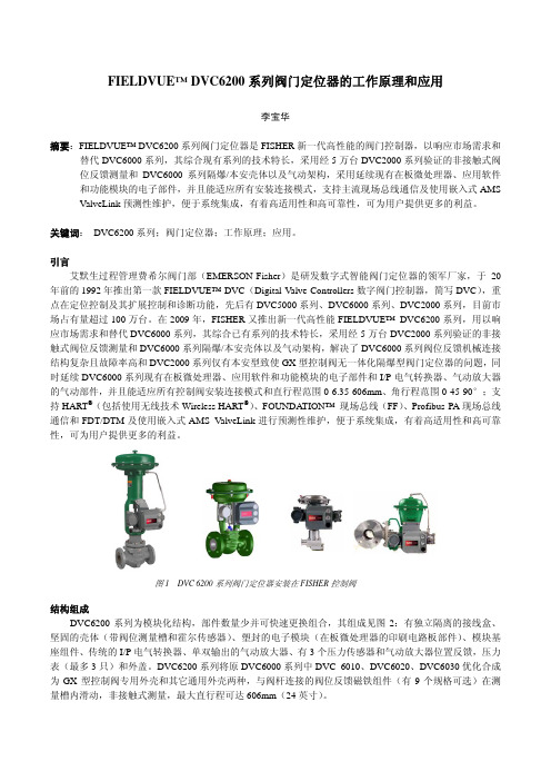
FIELDVUE™ DVC6200系列阀门定位器的工作原理和应用李宝华摘要:FIELDVUE™ DVC6200系列阀门定位器是FISHER 新一代高性能的阀门控制器,以响应市场需求和替代DVC6000系列,其综合现有系列的技术特长,采用经5万台DVC2000系列验证的非接触式阀位反馈测量和DVC6000系列隔爆/本安壳体以及气动架构,采用延续现有在板微处理器、应用软件和功能模块的电子部件,并且能适应所有安装连接模式,支持主流现场总线通信及使用嵌入式AMS ValveLink 预测性维护,便于系统集成,有着高适用性和高可靠性,可为用户提供更多的利益。
关键词: DVC6200系列;阀门定位器;工作原理;应用。
引言艾默生过程管理费希尔阀门部(EMERSON-Fisher )是研发数字式智能阀门定位器的领军厂家,于20年前的1992年推出第一款FIELDVUE™ DVC (Digital Valve Controllers 数字阀门控制器,简写DVC ),重点在定位控制及其扩展控制和诊断功能,先后有DVC5000系列、DVC6000系列、DVC2000系列,目前市场占有量超过100万台。
在2009年,FISHER 又推出新一代高性能FIELDVUE™ DVC6200系列,用以响应市场需求和替代DVC6000系列,其综合已有系列的技术特长,采用经5万台DVC2000系列验证的非接触式阀位反馈测量和DVC6000系列隔爆/本安壳体以及气动架构,解决了DVC6000系列阀位反馈机械连接结构复杂且故障率高和DVC2000系列仅有本安型致使GX 型控制阀无一体化隔爆型阀门定位器的问题,同时延续DVC6000系列现有在板微处理器、应用软件和功能模块的电子部件和I/P 电气转换器、气动放大器的气动部件,并且能适应所有控制阀安装连接模式和直行程范围0-6.35-606mm 、角行程范围0-45-90°;支持HART ®(包括使用无线技术Wireless HART ®)、FOUNDATION™ 现场总线(FF )、Profibus-PA 现场总线通信和FDT/DTM 及使用嵌入式AMS ValveLink 进行预测性维护,便于系统集成,有着高适用性和高可靠性,可为用户提供更多的利益。
HART手操器调试fisher费希尔dvc6200阀门定位器
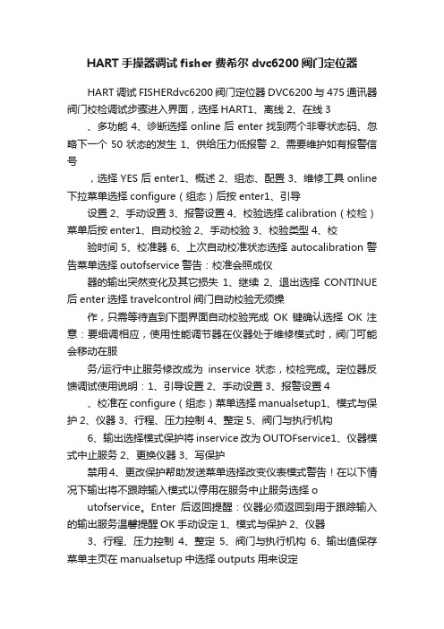
HART手操器调试fisher费希尔dvc6200阀门定位器HART调试FISHERdvc6200阀门定位器DVC6200与475通讯器阀门校检调试步骤进入界面,选择HART1、离线2、在线3 、多功能4、诊断选择online后enter找到两个非零状态码、忽略下一个50状态的发生1、供给压力低报警2、需要维护如有报警信号,选择YES后enter1、概述2、组态、配置3、维修工具online 下拉菜单选择configure(组态)后按enter1、引导设置2、手动设置3、报警设置4、校验选择calibration(校检)菜单后按enter1、自动校验2、手动校验3、校验类型4、校验时间5、校准器6、上次自动校准状态选择autocalibration警告菜单选择outofservice警告:校准会照成仪器的输出突然变化及其它损失1、继续2、退出选择CONTINUE 后enter选择travelcontrol阀门自动校验无须操作,只需等待直到下图界面自动校验完成OK键确认选择OK注意:要细调相应,使用性能调节器在仪器处于维修模式时,阀门可能会移动在服务/运行中止服务修改成为inservice状态,校检完成。
定位器反馈调试使用说明:1、引导设置2、手动设置3、报警设置4 、校准在configure(组态)菜单选择manualsetup1、模式与保护2、仪器3、行程、压力控制4、整定5、阀门与执行机构6、输出选择模式保护将inservice改为OUTOFservice1、仪器模式中止服务2、更换仪器3、写保护禁用4、更改保护帮助发送菜单选择改变仪表模式警告!在以下情况下输出将不跟踪输入模式以停用在服务中止服务选择o utofservice。
Enter后返回提醒:仪器必须返回到用于跟踪输入的输出服务温馨提醒OK手动设定1、模式与保护2、仪器3、行程、压力控制4、整定5、阀门与执行机构6、输出值保存菜单主页在manualsetup中选择outputs用来设定定位器反馈输出1、输出终端组态2、开关组态3、变送器输出4mA时=阀关4、HART变量分配选择outputterminal输出配置1、输出端激活/禁用2、功能发送器3、失败信号发射低/··选择outputterminalenable输出端选择启用禁用启用禁用选择enable后enter输出端配置1、输出启用2、功能变送器3、失败信号发射低/·发送主页一定要选择send发送后完成反馈使用设置。
美国FISHER调节阀阀门定位器DVC6200自整定
DVC6200与475通讯器阀门引导设置校检调试步骤
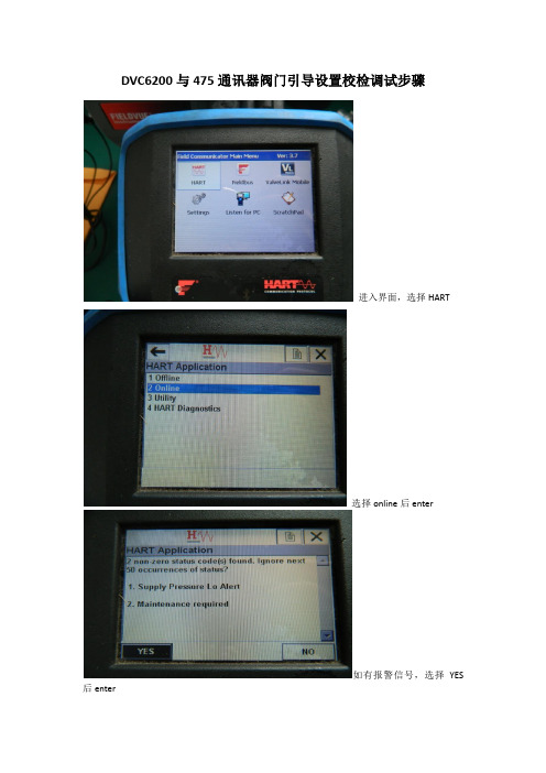
进入界面,选择HART
选择online后enter
如有报警信号,选择YES 后enter
online下拉菜单选择configure(组态)后按enter
选择guided setup(引导设置)菜单后按enter
选择device setup
警告菜单选择out of service
压力单位选择可任意,选择PSI
放大器类型,选择A OR C用于单作用和双作用放大器,B为反作用定位器。
选择travel control
执行器制造厂商选择fisher
执行器的型号更具执行器名牌选择。
执行器尺寸型号选择根据执行器名牌进行输入
失电阀门开或者关,据条件选择
选择YES
定位器自动捕行程传感器方向。
等待下图界面弹出
是否含有快排和气体流量放大器,没有选择no。
否则YES
发送设备设置数据给仪表,按enter
等待发送,发送完成后如下图界面
使用工厂默认设置选择YES
发送工厂默认数据中,等待完成后出现下图界面
设备设置完成选OK,按Enter
运行阀门行程校验,选择ok后enter
选择yes
阀门自动校验中
阀门自动校验中
自动校验中
阀门校检完成ok后按enter
选择ok
校验完成后恢复到in service 状态。
阀门自动校验步骤完成。
DVC6200系列阀门定位器的工作原理和应用
DVC6200系列阀门定位器的工作原理和应用DVC6200系列阀门定位器是Fisher全球阀门定位器系列中的一种产品。
它采用了先进的技术和设计,在控制阀门的位置和运动方面具有高效性和精确性。
以下将对DVC6200系列阀门定位器的工作原理和应用进行详细介绍。
1.位置传感:DVC6200系列阀门定位器通过内置的位置传感器来检测阀门的当前位置。
传感器可以准确地测量阀门的开度,并将此信息反馈给控制系统。
2.位置调节:根据控制系统的设定值,DVC6200系列阀门定位器会自动调整阀门的位置。
这个过程通过电机和驱动系统来实现。
电机会根据传感器的反馈信息,不断地调整阀门的位置,直到达到预设的开度。
1.过程控制:DVC6200系列阀门定位器可以与控制系统集成,实现对工业过程的精确控制。
例如,在化工生产中,可以通过精细控制阀门开度,调整反应中的物质流动速度,以实现更高的产品质量和产量。
2.能源管理:DVC6200系列阀门定位器可以用于石油、天然气和电力等领域的阀门控制。
通过精确控制阀门开度,可以实现对流体的快速切断和调节,以提高能源利用效率和安全性。
3.污水处理:在污水处理厂中,DVC6200系列阀门定位器可以用于控制水泵、阀门和其他设备的运行,以实现对污水的处理效果和流量的控制。
4.制药和食品加工:在制药和食品加工领域,对液体和气体的精确控制非常重要。
DVC6200系列阀门定位器的高精度和可靠性,可以确保在生产过程中获得稳定和优质的产品。
总结:DVC6200系列阀门定位器是一种基于电气信号的位置控制系统,通过精确的位置传感和位置调节,实现对阀门的精确控制。
它在各个领域的工业应用中起着非常重要的作用,特别适用于过程控制、能源管理、污水处理和制药食品加工等领域。
Fisher FIELDVUE DVC6200系列数字阀控制器的危险区域批准和特殊安装说明书

Digital Valve ControllersHazardous Area Approvals and Special Instructionsfor “Safe Use” and Installations in Hazardous LocationsCertain nameplates may carry more than one approval, and each approval may have unique installation/wiring requirements and/or conditions of “safe use”. These special instructions for “safe use” are in addition to, and may override, the standard installation procedures. Special instructions are listed by approval type.NoteThis information supplements the nameplate markings affixed to the product and the DVC6200 Series quick start guide(D103556X012), available from your Emerson sales office or Local Business Partner, or at .Always refer to the nameplate itself to identify the appropriate certification.WARNINGFailure to follow these conditions of “safe use” could result in personal injury or property damage from fire or explosion and area re‐classification.Ordinary Locations ApprovalComplies with general electrical safety CAN/CSAC22.2 No. 6101012004SELV, conduit connected, Enclosure Type 4X, IP66, Installation Category I, Pollution Degree 4DVC6200 Series (HART HW1, F OUNDATION Fieldbus, PROFIBUS) Rated Input 9-30 VDC, 4-20 mA -52_C to + 80_C AmbientDVC6205 (HART HW1, F OUNDATION fieldbus, PROFIBUS) DVC6215 Remote Mount Rated Input 9-30 VDC, 4-20 mA Rated Input 10 VDC max, 3.5 mA max Outputs 0-9.6 VDC, 0-3.5 mA -52 to 125_C Ambient -52_C to + 80_C AmbientExplosion-proof and Dust Ignition-proofDVC6200 and DVC6205 Series (HART HW1 & HW2, SIS, F OUNDATION Fieldbus, PROFIBUS) Class I, Division 1, Groups B,C,D ; Class I, Division 2, Groups A,B,C,DClass II, Division 1, Groups E,F,G ; Class II, Division 2, Groups F,GClass III, Division 1Ex d IICEx nC IICType 4X, IP66Single Seal Device (HART HW2 and SIS pending)Rated input 30 Vmax, 20 mA- 52_C < Ambient < + 80_CMax inlet pressure 10 bar (145 psig) (air or natural gas)Temperature Code: T6 (Tamb ≤ 75_C), T5 (Tamb ≤ 80_C)DVC6215 Remote MountClass I, Division 1, Groups A,B,C,D ; Class I, Division 2, Groups A,B,C,DClass II, Division 1, Groups E,F,G ; Class II, Division 2, Groups F,GClass III, Division 1Ex d IICEx nA IICType 4X, IP66Rated input 30 Vmax, 20 mA- 52_C < Ambient < + 125_CTemperature Code: T6 (Tamb ≤ 75_ C), T5 (Tamb ≤ 90_C), T4 (Tamb ≤ 125_C)Intrinsically SafeClass I, Division 1, Groups A,B,C,DClass II, Division 1, Groups E,F,GClass III, Division 1Ex ia IICType 4X, IP66Single Seal Device (HART HW2 and SIS pending)Rated input 30 V DC max, 20 mA- 52 _C < Ambient < + 80_C (-52_C to 125_C for DVC6215)Max inlet pressure 10 bar (145 psig) (air or natural gas)Intrinsically safe when connected per installation drawing GE42818, as shown in the following figures DVC6200 HW2 and DVC6200 SIS figure 1 and 6...................................DVC6205, DVC6205 SIS, and DVC6215 Remote Mount figure 2 and 6.................................DVC6200f and DVC6200p figure 3 and 6.........DVC6205f, DVC6205p, and DVC6215 Remote Mount figure 4 and 6...........................................DVC6200 HW1 figure 5 and 6231 SEE NOTES IN FIGURE 6GE42818 Sheet 11, Rev. CCLASS I, ZONE 0, GROUP IIC CLASS I, DIV 1, GROUPS ABCD CLASS II, DIV 1, GROUPS EFG CLASS IIILOOP TERMINALS Vmax = 30 VDC Imax = 130 mA Ci = 15 nF Li = 0.55 mH Pi = 1.0 WHAZARDOUS LOCATIONPOWER MAY BE APPLIED TOEITHER THE LOOP TERMINALS OR OUTPUT TERMINALS OR TO BOTH SETS OF TERMINALS AT THE SAME TIMEUNITS WITHOUT THE I/O PACKAGE WILL NOT HAVE “OUTPUT TERMINALS” AVAILABLE FOR CONNECTION1 NOTE 7Figure 1. CSA Loop Schematics—FIELDVUE DVC6200 HW2 and DVC6200 SIST CODE T (amb) T (amb)T5 ≤ 80_C ≤ 80_C NON‐HAZARDOUS LOCATIONCSA APPROVED BARRIERHW2 - WITH OR WITHOUT I/O PACKAGE DVC6200, DVC6200ST6 ≤ 61_C ≤ 74_CCSA APPROVED BARRIERNOTE 1, 3, 4, 5, 6 1OUTPUT TERMINALS Vmax = 28 VDC Imax = 100 mA Ci = 15 nF Li = 0.5 mH Pi = 1.0 WWITH I/O PACKAGE WITHOUT I/O PACKAGENOTE 1, 3, 4, 5, 6 14Figure 2. CSA Loop Schematics—FIELDVUE DVC6205, DVC6205 SIS, and DVC62151 SEE NOTES IN FIGURE 6GE42818 Sheet 12, Rev. CCLASS I, ZONE 0, GROUP IIC CLASS I, DIV 1, GROUPS ABCD CLASS II, DIV 1, GROUPS EFG CLASS IIIREMOTEFIELD WIRING TERMINAL BOXHAZARDOUS LOCATIONPOWER MAY BE APPLIED TO EITHER THE LOOP TERMINALS OR OUTPUT TERMINALS OR TO BOTH SETS OF TERMINALS AT THE SAME TIME UNITS WITHOUT THE I/O PACKAGE WILL NOT HAVE “OUTPUT TERMINALS”AVAILABLE FOR CONNECTIONNOTE 7T CODE T (amb) T (amb)T5 ≤ 80_C ≤ 80_C 1NON‐HAZARDOUS LOCATIONCSA APPROVED BARRIERHW2 - WITH OR WITHOUT I/O PACKAGEDVC6205NOTE 1, 3, 4, 5, 6 1T6 ≤ 61_C ≤ 74_CCSA APPROVED BARRIERNOTE 1, 3, 4, 5, 6 1DVC6215Vmax = 30 VDC Imax = 226 mA Ci = 50 nF Li = 0.55 mH Pi = 1.4 W WITH I/O PACKAGE WITHOUT I/O PACKAGECLASS I, ZONE 0, GROUP IIC CLASS I, DIV 1, GROUPS ABCD CLASS II, DIV 1, GROUPS EFG CLASS IIIVoc = 30 VDC Isc = 21.2 mA Ca = 55 nF La = 78 mH Po = 160 mWLOOP TERMINALS Vmax = 30 VDC Imax = 130 mA Ci = 15 nF Li = 0.55 mH Pi = 1.0 WOUTPUT TERMINALS Vmax = 28 VDC Imax = 100 mA Ci = 15 nF Li = 0.5 mH Pi = 1.0 WFIELD WIRING TERMINAL BOXT CODE T (amb)T5 ≤ 90_C T6 ≤ 75_CT4 ≤ 125_C NOTE 1, 3 151 SEE NOTES IN FIGURE 6FISCO LOOPENTITY FIELDBUS LOOPGE42818 Sheet 4, Rev. F1 NOTE 7NON‐HAZARDOUS LOCATIONCLASS I, ZONE 0, GROUP IIC CLASS I, DIV 1, GROUPS ABCD CLASS II, DIV 1, GROUPS EFG CLASS IIIDVC6200F, DVC6200FS DVC6200P, DVC6200PSHAZARDOUS LOCATION CSA APPROVED BARRIERHAZARDOUS LOCATION NON‐HAZARDOUS LOCATIONCSA APPROVED FISCO BARRIER CSA APPROVED FISCO TERMINATORCSA APPROVED FISCO DEVICEDVC6200F, DVC6200FS DVC6200P, DVC6200PSCLASS I, ZONE 0, GROUP IIC CLASS I, DIV 1, GROUPS ABCD CLASS II, DIV 1, GROUPS EFG CLASS IIICSA APPROVED ENTITY DEVICENOTE 1, 3 11 NOTE 1, 3, 4, 5, 61 NOTE 2, 3, 4, 5, 6NOTE 2, 3 1Figure 3. CSA Loop Schematics—FIELDVUE DVC6200f and DVC6200pT CODE T (amb)T4 ≤ 80_C T6 ≤ 62_CT5 ≤ 77_C T CODE T (amb)T4 ≤ 80_C T6 ≤ 62_CT5 ≤ 77_C GE42818 Sheet 3, Rev. FVmax = 24 VDC Imax = 380 mA Ci = 5 nF Li = 0 mH Pi = 1.4 WVmax = 17.5 VDC Imax = 380 mA Ci = 5 nF Li = 0 mH Pi = 5.32 W1 SEE NOTES IN FIGURE 661 SEE NOTES IN FIGURE 6CSAAPPROVED ENTITY DEVICEHAZARDOUS LOCATIONNON‐HAZARDOUS LOCATIONCLASS I, ZONE 0, GROUP IIC CLASS I, DIV 1, GROUPS ABCD CLASS II, DIV 1, GROUPS EFG CLASS IIIVmax = 30 VDC Imax = 226 mA Ci = 50 nF Li = 0.55 mH Pi = 1.4 WCSA APPROVED BARRIERNON‐HAZARDOUS LOCATIONHAZARDOUS LOCATIONENTITY FIELDBUS LOOPCSA APPROVED FISCO BARRIERCSA APPROVED FISCOTERMINATORCSAAPPROVED FISCO DEVICEFISCO LOOP1 NOTE 1, 3, 4, 5, 6NOTE 1, 3 1NOTE 7 11 NOTE 2, 3, 4, 5, 6NOTE 2, 3 1GE42818 Sheet 10, Rev. DT CODE T (amb)T4 ≤ 80_C T6 ≤ 62_CT5 ≤ 77_C Figure 4. CSA Loop Schematics—FIELDVUE DVC6205f, DVC6205p, and DVC6215NOTE 1 1DVC6205f, DVC6205p Voc = 24 VDC Isc = 17.5 mA Ca = 121 nF La = 100 mH Po = 105 mWVmax = 24 VDC Imax = 380 mA Ci = 5 nF Li = 0 mH Pi = 1.4 WDVC6215Vmax = 30 VDC Imax = 226 mA Ci = 50 nF Li = 0.55 mH Pi = 1.4 WVmax = 17.5 VDC Imax = 380 mA Ci = 5 nF Li = 0 mH Pi = 5.32 WDVC6215CLASS I, ZONE 0, GROUP IIC CLASS I, DIV 1, GROUPS ABCD CLASS II, DIV 1, GROUPS EFG CLASS IIIDVC6205f, DVC6205p Voc = 17.5 VDC Isc = 17.5 mA Ca = 121 nF La = 100 mH Po = 105 mWNOTE 2 1CLASS I, ZONE 0, GROUP IIC CLASS I, DIV 1, GROUPS ABCD CLASS II, DIV 1, GROUPS EFG CLASS IIICLASS I, ZONE 0, GROUP IIC CLASS I, DIV 1, GROUPS ABCD CLASS II, DIV 1, GROUPS EFG CLASS IIIT CODE T (amb)T4 ≤ 125_C T6 ≤ 75_CT5 ≤ 90C T CODE T (amb)T4 ≤ 80_C T6 ≤ 62_CT5 ≤ 77_C T CODE T (amb)T4 ≤ 125_C T6 ≤ 75_CT5 ≤ 90C GE42818 Sheet 9, Rev. D1 SEE NOTES IN FIGURE 67GE42818 sheet 2, Rev. FCSA APPROVED BARRIER1 NOTE 1, 3, 4, 5, 61 NOTE 7CLASS I, ZONE 0, GROUP IIC CLASS I, DIV 1, GROUPS ABCD CLASS II, DIV 1, GROUPS EFG CLASS IIIDVC6200, DVC6200SNON‐HAZARDOUS LOCATIONHAZARDOUS LOCATIONFigure 5. CSA Loop Schematic—FIELDVUE DVC6200 HW11 SEE NOTES IN FIGURE 6T6 ≤ 75_CT5 ≤ 80_C T CODE T (amb)Vmax = 30 VDC Imax = 226 mA Ci = 5 nFLi = 0.55 mH Pi = 1.4 WTHE ENTITY CONCEPT ALLOWS INTERCONNECTION OF INTRINSICALLY SAFE APPARATUS TO ASSOCIATED APPARATUS NOTSPECIFICALLY EXAMINED IN SUCH COMBINATION. THE CRITERIA FOR INTERCONNECTION IS THAT THE VOLTAGE (Vmax or Ui), THE CURRENT (Imax or Ii), AND THE POWER (Pmax or Pi) OF THE INTRINSICALLY SAFE APPARATUS MUST BE EQUAL TO OR GREATER THAN THE VOLTAGE (Voc or Uo), AND THE CURRENT (Isc or Io), AND THE POWER(Po) D EFINED BY THE ASSOCIATED APPARATUS. IN ADDITION, THE SUM OF THE MAX UNPROTECTED CAPACITANCE (Ci) AND MAX UNPROTECTED INDUCTANCE (Li), INCLUDING THE INTERCONNECTING CABLING CAPACITANCE (Ccable) AND CABLING IND UCTANCE (Lcable) MUST BE LESS THAN THE ALLOWABLE CAPACITANCE (Ca) AND INDUCTANCE (La) DEFINED BY THE ASSOCIATED APPARATUS. IF THE ABOVE CRITERIA IS MET, THEN THE COMBINATION MAY BE CONNECTED.Vmax or Ui . Voc or Uo Imax or Ii . Isc or Io Pmax or Pi . Po Ci + Ccable ≤ Ca Li + Lcable ≤ LaTHE FISCO CONCEPT ALLOWS INTERCONNECTION OF INTRINSICALLY SAFE APPARATUS TO ASSOCIATED APPARATUS NOTSPECIFICALLY EXAMINED IN SUCH COMBINATION. THE CRITERIA FOR THE INTERCONNECTION IS THAT THE VOLTAGE (Vmax or Ui),CURRENT (Imax or Ii), AND POWER (Pmax or Pi), WHICH AN INTRINSICALLY SAFE APPARATUS CAN RECEIVE AND REMAIN INTRINSICALLY SAFE, CONSIDERING FAULTS, MUST BE EQUAL TO OR GREATER THAN THE VOLTAGE (Voc or Uo), CURRENT (Isc or Io),AND POWER (Po) LEVELS WHICH CAN BE D ELIVERED BY THE ASSOCIATED APPARATUS, CONSID ERING FAULTS AND APPLICABLE FACTORS. IN ADDITION THE MAXIMUM UNPROTECTED CAPACITANCE (Ci) AND INDUCTANCE (Li) OF EACH APPARATUS (OTHER THAN THE TERMINATION) CONNECTED TO THE FIELDBUS MUST BE LESS THAN OR EQUAL TO 5 nF AND 10 uH RESPECTIVELY.IN EACH SEGMENT ONLY ONE ACTIVE DEVICE, NORMALLY THE ASSOCIATED APPARATUS, IS ALLOWED TO PROVIDE THE NECESSARY ENERGY FOR THE FIELDBUS SYSTEM. THE VOLTAGE (Uo or Voc or Vt) OF THE ASSOCIATED APPARATUS HAS TO BE LIMITED TO THE RANGE OF 9 V TO 17.5 VDC. ALL OTHER EQUIPMENT CONNECTED TO THE BUS CABLE HAS TO BE PASSIVE, MEANING THAT THEY ARE NOT ALLOWED TO PROVID E ENERGY TO THE SYSTEM, EXCEPT FOR A LEAKAGE CURRENT OF 50 uA FOR EACH CONNECTED D EVICE.SEPARATELY POWERED EQUIPMENT NEEDS A GALVANIC ISOLATION TO ASSURE THAT THE INTRINSICALLY SAFE FIELDBUS CIRCUIT REMAINS PASSIVE.CONTINUED ON NEXT PAGE…Figure 6. Notes for CSA Loop SchematicsCONTINUEDTHE CABLE USED TO CONNECT THE DEVICES NEEDS TO HAVE THE PARAMETERS IN THE FOLLOWING RANGE:LOOP RESISTANCE R': 15 TO 150 ohms/km INDUCTANCE PER UNIT LENGTH L: 0.4 TO 1 mH/km CAPACITANCE PER UNIT LENGTH C': 80 TO 200 nF/kmC' = C' LINE/LINE + 0.5' LINE/SCREEN, IF BOTH LINES ARE FLOATING ORC' = C' LINE/LINE + C' LINE/SCREEN, IF THE SCREEN IS CONNECTED TO ONE LINE.LENGTH OF SPLICE: < 1 m (T‐BOX MUST ONLY CONTAIN TERMINAL CONNECTIONS WITH NO ENERGY STORAGE CAPABILITY)LENGTH OF SPUR CABLE: < 30 M LENGTH OF TRUNK CABLE: < 1 kmAT EACH END OF THE TRUNK CABLE AN APPROVED INFALLIBLE TERMINATION WITH THE FOLLOWING PARAMETERS IS SUITABLE: R = 90 TO 100 ohms AND C = 0 TO 2.2 uFNOTE, A BUILT‐IN TERMINATOR IS INCLUDED IN THE FIELD SIDE AND A SELECTABLE TERMINATOR IS AVAILABLE ON THE HOST SIDE.THE NUMBER OF PASSIVE DEVICES CONNECTED TO THE BUS SEGMENT IS NOT LIMITED IN THE FISCO CONCEPT FOR INTRINSICALLY SAFE REASONS. IF THE ABOVE RULES ARE RESPECTED, UP TO A TOTAL LENGTH OF 1000 m (SUM OF THE LENGTH OF THE TRUNK CABLE AND ALL SPUR CABLES), THE IND UCTANCE AND CAPACITANCE OF THE CABLE WILL NOT IMPAIR THE INTRINSIC SAFETY OF THE INSTALLATION.INSTALLATION MUST BE IN ACCORDANCE WITH THE CANADIAN ELECTRICAL CODE (CEC) AND ANSI/ISA RP12.6. MAXIMUM SAFE AREA VOLTAGE SHOULD NOT EXCEED 250 Vrms.RESISTANCE BETWEEN INTRINSICALLY SAFE GROUND AND EARTH GROUND MUST BE LESS THAN ONE OHM LOOPS MUST BE CONNECTED ACCORDING TO THE BARRIER MANUFACTURER'S INSTRUCTIONS.IF HAND‐HELD COMMUNICATOR OR MULTIPLEXER IS USED, IT MUST BE CSA APPROVED WITH ENTITY PARAMETERS AND INSTALLEDPER THE MANUFACTURER'S CONTROL DRAWINGS.GE42818 Sheet 8, Rev. EFigure 6. Notes for CSA Loop Schematics (continued)Emerson Automation Solutions Marshalltown, Iowa 50158 USA Sorocaba, 18087 Brazil Cernay, 68700 FranceDubai, United Arab Emirates Singapore 128461 SingaporeThe contents of this publication are presented for informational purposes only, and while every effort has been made to ensure their accuracy, they are not to be construed as warranties or guarantees, express or implied, regarding the products or services described herein or their use or applicability. All sales are governed by our terms and conditions, which are available upon request. We reserve the right to modify or improve the designs or specifications of such products at any time without notice.Fisher and FIELDVUE are marks owned by one of the companies in the Emerson Automation Solutions business unit of Emerson Electric Co. EmersonAutomation Solutions, Emerson, and the Emerson logo are trademarks and service marks of Emerson Electric Co. All other marks are the property of their respective owners.Neither Emerson, Emerson Automation Solutions, nor any of their affiliated entities assumes responsibility for the selection, use or maintenance of any product. Responsibility for proper selection, use, and maintenance of any product remains solely with the purchaser and end user.。
菲舍尔 FIELDVUE DVC6200 数字阀门控制器安装说明书

Use these instructions to mount a Fisher r FIELDVUE t DVC6200 digital valve controller mounting kit forUniversal (side mounting), sliding stem applications.Avoid personal injury or propertydamage from sudden release of processpressure or bursting of parts. Beforeperforming any installation operations:D Always wear protective clothing,gloves, and eyewear.D Do not remove the actuator fromthe valve while the valve is stillpressurized.D Disconnect any operating linesproviding air pressure, electric power, ora control signal to the actuator. Be surethe actuator cannot suddenly open orclose the control valve.D Use bypass valves or completelyshut off the process to isolate the controlvalve from process pressure. Relieveprocess pressure from both sides of thecontrol valve.D Use lock‐out procedures to be sure that the above measures stay in effectwhile you work on the equipment.D Check with your process or safety engineer for any additional measuresthat must be taken to protect againstprocess media.D Vent the pneumatic actuatorloading pressure and relieve anyactuator spring precompression so theactuator is not applying force to thevalve stem; this will allow for the saferemoval of the stem connector.Refer to figures 7, 8 and 9 for mounting parts identification. Hex key, 2.5 hex, L-key flat end, long (key 15) is to be used to secure the M4 hex socket button head screws (key 4). Refer to the DVC6200 digital valve controller instruction manual for digital controller parts identification. Refer to the appropriate actuator instruction manual for actuator installation, operation, maintenance, and parts identification.1. Isolate the control valve from the process line pressure and release pressure from both sides of the valve body. Shut off all pressure lines to the actuator, releasing all pressure from the actuator. Use lock-out procedures to be sure that the above measures stay in effect while you work on the equipment.2. Determine the stem diameter (must not be smaller than 6.35 mm (0.25 Inch) mm and not larger than 25.4 mm (1.00 inch). Use the stem blocks and shims in the kit, drill out the stem block assembly to the actuator stem dimension (see figure 1). Once desired diameter is reached, loosen the two stem block assembly screws and remove the shims.Figure 1. Stem Block AssemblySTEM BLOCK ASSEMBLED WHEN DRILLINGMAX. BORE, 25.4 (1.00)MIN. BORE, 6.35 (0.25)SHIMSSHIMSTEM BLOCK HALF (BACK)STEM BLOCK HALF (FRONT)(2) SCREW, CAP, HEX SOCKETM8X1.25X35SHIMmm (INCH)3. Attach the stem block to the stem, in relationship to the desired location of the mounting bracket (key 5). Use the (2) M8x1.25x35 screws to secure the stem block to the stem in the predetermined position.DVC6200 Digital Valve ControllerMounting Kit for Universal (Side Mounting)Sliding-Stem Actuator ApplicationsMounting InstructionsD103778X012June 20132Figure 2. Rib Style Yoke95.3 (3.75) MIN 120.7 (4.75) MAX76.2 (3.00) MIN 156.2 (6.15) MAXmm (INCH)1 1 MUST HAVE CLEARANCE FOR STEM BLOCK ASSEMBLYFigure 3. Stanchion Style Yoke94 (3.70) MIN 119.4 (4.70) MAX76.2 (3.00) MIN 156.2 (6.15) MAX11 MUST HAVE CLEARANCE FOR STEM BLOCK ASSEMBLYmm (INCH)NoteWhen the stem is in either the fully open or fully closed position, the distance from the centerline of the mounting bracket (key 5) and the centerline of the stem block assembly should not exceed (see figure 15).4. Revisit the desired location of the mounting bracket.a. If actuator has a NAMUR rib (figure 2 and 7),verify the width of the yoke is a minimum of 152.4mm (6.00 inch) up to a maximum of 155.7 mm (6.13 inch). Once this is verified, ensure the distance from the face of the mounting bracket (key 5) to the mounting face of the stem blockassembly is a minimum of 95.3 mm (3.75 inch) and not more than 98.6 mm (3.88 inch). Attachmounting bracket (key 5) using either 5/16-18 X 1.375 inch hex head screw(s) or M8 X 1.25 X 36mm hex head screw(s) (key 8)(see figure 2 and 7).b. If actuator has a stanchion style yoke, verify the width of the yoke is a minimum of 144.8 mm (5.70 inch) up to a maximum of 147.3 mm (5.80inch). Once this is verified, ensure the distance from the face of the mounting bracket (key 5) to the mounting face of the stem block assembly is a minimum of 94 mm (3.70 inch) and not more than 98.55 mm (3.80 inch). Attach mounting bracket (key 5) using M8x1.25x35x69 U-bolts (key 13) (see figures 3 and 8).c. If actuator has a Plane Surface style yoke, verify the width of the yoke is a minimum of 162.6 mm (6.40 inch) up to a maximum of 165.1 mm (6.50inch). Once this is verified, ensure the distance from the face of the mounting bracket (key 5) to the mounting face of the stem block assembly is a minimum of 95.3 mm (3.75 inch) and not more than 98.6 mm (3.88 inch).These holes can be tapped either for 5/16-18 or M8 X 1.25 hardware. Attach the mounting bracket (key 5) using either 5/16-18 X 1.375 inch hex head screws or M8 X 1.25 X 36 mm hex head screws (see figure 9).DVC6200 Digital Valve ControllerMounting Kit for Universal (Side Mounting)Sliding-Stem Actuator ApplicationsMounting InstructionsD103778X012June 20133Figure 4. Plane Surface Yoke84.3 (3.32) MIN 109.7 (4.32) MAX80 (3.15) MIN 160 (6.30) MAXmm (INCH)1 1 MUST HAVE CLEARANCE FOR STEM BLOCK ASSEMBLYFigure 5. Mounting Holes43 (1.69)43 (1.69)(4) M8X1.25 OR 5/16-18mm (INCH) 5. Ensure the actuator/valve stem connectormounting face is visually square with the actuator yoke legs.6. Attach the connector arm (key 7) to the stemconnector using the two hex head cap screws (key 11)and plain washers (key 9), but do not tighten (see figure 7, 8 and 9). See figure 10 through 14 for the proper arrangement for your application.7. Attach the adjustment arm (key 3) to the connector arm (key 7) with two M4 flange socket head machine screws (key 4) securely but do not tighten to maintain adjustability (see figure 7, 8 and 9).8. Attach the magnet assembly (array) (key 12) to the extension arm (key 6) with two M4 flange socket head machine screws (key 4) securely but maintain adjustability (see figure 7, 8 and 9).9. Attach the extension arm (key 6) and the magnet assembly (array) (key 12) to the adjustment arm (key 3) using two M4 flange socket head machinescrews, (key 4) securely but maintain adjustability. The next step will ensure that the connector arm (key 7)selected is suitable (see figure 6).Figure 6. Connector Arm Selection(A)(B)ARRAYFIGURE SHOWS MAGNET ASSEMBLY MARKING ALIGNED WITH SENSOR INDEX MARK FORAIR-TO-EXTEND ACTUATORSASSEMBLY MARKINGALIGNMENT TEMPLATEA) CONNECTOR ARM FOR LARGER SIZE ACTUATORS B) CONNECTOR ARM FOR SMALLER SIZE ACTUATORSDVC6200 Digital Valve ControllerMounting Kit for Universal (Side Mounting)Sliding-Stem Actuator ApplicationsMounting InstructionsD103778X012June 2013410. Attach the black plastic alignment template (see figure 6) to the mounting bracket assembly by inserting the two protruding posts into the two recessed mounting holes in the bracket andsimultaneously position the magnet assembly (array)so that it can slide into the channel in the alignment bracket. The magnet assembly (array) should be fully in the alignment template channel so that theextension arm is contacting the back of the alignment template but not bending it. Tighten the hex head cap screws (key 11) at the stem connector and pan head machine screws (key 4) attaching the extension arm to the connector arm but do not yet tighten the pan head machine screws attaching the magnet assembly (array).11. For an air-to-extend actuator, slide the magnet assembly (array) (key 12) so that the bottom marking aligns with the sensor index mark on the alignment template (figure 6). The top marking of the magnet assembly (array) is used for air-to-retract. The mounting bracket (key 5) may require verticalrepositioning to get the magnet assembly (array) (key 12) in the correct location. When the magnet assembly (array) (key 12) is properly positioned,remove the alignment template (see figure 6) and tighten the two pan head machine screws (key 4).12. Attach the digital valve controller to the mounting bracket assembly and tighten the three hex head cap screws (key 10) (see figure 7, 8 and 9).13. Check the position of the magnet assembly (array)(key 12) in the channel of the digital valve controller housing and ensure that it is visually centered between the channel walls and has adequate clearance with the backside of the channel (approximately 3 mm).14. Connect and calibrate the digital valve controller as described in the instruction manual or quick start guide.For additional information concerning the mounting,setup, calibration and maintenance of the DVC6200digital valve controller, refer to the appropriate instruction manual or quick start guide.DVC6200 Digital Valve ControllerMounting Kit for Universal (Side Mounting)Sliding-Stem Actuator ApplicationsMounting InstructionsD103778X012June 20135Figure 7. Mounting on Actuator with NAMUR Rib Yoke154643911211105728DVC6200DESCRIPTION UNIV_RIB-YOKE WASHER, LOCK M8ARM, ADJUSTMENTSCREW, CAP HEX SOCKET M4X0.7X10 FLANGED BUTTON BRACKET, MOUNTING ARM, EXTENSIONARM, CONNECTOR (CHOOSE ONE)SCREW, CAP HEX HD M8X1.25X36 OR 5/16-18X1.375WASHER, PLAIN M6SCREW, CAP, HEX HD M8X1.25X16SCREW, CAP, HEX HD M6X1X12FEEDBACK ARRAY NOT USED THIS VIEW NOT USED THIS VIEWHEX, KEY 2.5 HEX, L-KEY FLAT END LONGITEM 123456789101112131415QTY 111611112321001PARTS LISTDVC6200 Digital Valve ControllerMounting Kit for Universal (Side Mounting)Sliding-Stem Actuator ApplicationsMounting InstructionsD103778X012June 20136Figure 8. Mounting on Actuator with Stanchion Style Yoke1546439112111057213DVC620014DESCRIPTIONUNIV_PILLAR-YOKEWASHER, LOCK MM8, 1X14.5X2.0ARM, ADJUSTMENTSCREW, CAP HEX SOCKET M4X0.7X10 FLANGED BUTTON BRACKET, MOUNTING ARM, EXTENSIONARM, CONNECTOR (CHOOSE ONE)NOT USED THIS VIEW WASHER, PLAIN M6SCREW, CAP, HEX HD M8X1.25X16SCREW, CAP, HEX HD M6X1X12FEEDBACK ARRAY U-BOLT M8X1.25NUT, HEX M8X1.25-6HHEX, KEY 2.5 HEX, L-KEY FLAT END LONGITEM 123456789101112131415QTY 141611142321001PARTS LISTDVC6200 Digital Valve ControllerMounting Kit for Universal (Side Mounting)Sliding-Stem Actuator ApplicationsMounting InstructionsD103778X012June 20137Figure 9. Mounting on Actuator with Plane Surface Style YokeDESCRIPTIONUNIV_PLANE-SURF-YOKE WASHER, LOCK M8 or 5/16ARM, ADJUSTMENTSCREW, CAP HEX SOCKET M4X0.7X10 FLANGED BUTTON BRACKET, MOUNTING ARM, EXTENSIONARM, CONNECTOR (CHOOSE ONE)SCREW, CAP, HEX HD M8X1.25X35 OR 5/16-18X1.375WASHER, PLAIN 6.4X12X1.6SCREW, CAP, HEX HD M8X1.25X16SCREW, CAP, HEX HD M6X1X12FEEDBACK ARRAY NOT USED THIS VIEW NOT USED THIS VIEWHEX, KEY 2.5 HEX, L-KEY FLAT END LONGITEM 123456789101112131415QTY 141611142321001PARTS LIST154643911211105728DVC6200DVC6200 Digital Valve ControllerMounting Kit for Universal (Side Mounting)Sliding-Stem Actuator ApplicationsMounting InstructionsD103778X012June 20138Figure 10.MINIMUM AND MAXIMUM OF ARM ADJUSTMENTMIN 96.5(3.80)MAX 121.9(4.80)MAX AND MIN BRACKET “A”(SEE FIGURE 6)MAX AND MIN BRACKET “B”(SEE FIGURE 6)15.2(0.60)48.5(1.91)33.3(1.31)17.3(0.68)45.2(1.78)63(2.48)mm (INCH)DVC6200 Digital Valve ControllerMounting Kit for Universal (Side Mounting)Sliding-Stem Actuator ApplicationsMounting InstructionsD103778X012June 20139Figure 11.STEMCONNECTOR ARM “A” OR “B”(SEE FIGURE 6)SCREW, CAP, HEX SOCKET (KEY 4)(SEE FIGURE 7, 8 AND 9)STEM BLOCK ASSEMBLY(SEE FIGURE 1)ARM, ADJUSTMENT (KEY 3)(SEE FIGURE 7, 8 AND 9)ARM, EXTENSION (KEY 6)(SEE FIGURE 7, 8 AND 9)ARM EXTENSION MAX DOWNARM EXTENSIONMAX UP17.8(0.70)86.9(3.42)125.2(4.93)25.1(0.99)26.9(1.06)8.6(0.34)125.2(4.93)8.6(0.34)86.4(3.40)95(3.74)105.6(4.16)mm (INCH)STEMCONNECTOR ARM “A” OR “B”(SEE FIGURE 6)SCREW, CAP, HEX SOCKET (KEY 4)(SEE FIGURE 7, 8 AND 9)STEM BLOCK ASSEMBLY (SEE FIGURE 1)ARM, ADJUSTMENT (KEY 3)(SEE FIGURE 7, 8 AND 9)ARM, EXTENSION (KEY 6)(SEE FIGURE 7, 8 AND 9)ARM EXTENSION MAX DOWNARM EXTENSIONMAX UP65.5(2.58)48.5(1.91)29.2(1.15)125.2(4.93)29.7(1.17)95(3.74)48.8(1.92)125.2(4.93)mm (INCH)Figure 12.DVC6200 Digital Valve ControllerMounting Kit for Universal (Side Mounting)Sliding-Stem Actuator ApplicationsMounting InstructionsD103778X012June 201310Figure 13.STEMCONNECTOR ARM “A” OR “B”(SEE FIGURE 6)SCREW, CAP, HEX SOCKET (KEY 4)(SEE FIGURE 7, 8 AND 9)STEM BLOCK ASSEMBLY (SEE FIGURE 1)ARM, ADJUSTMENT (KEY 3)(SEE FIGURE 7, 8 AND 9)ARM, EXTENSION (KEY 6)(SEE FIGURE 7, 8 AND 9)ARM EXTENSION (KEY 3)TURNED OVER MAX DOWN121.4 (4.78) MAX125.2(4.93)95(3.74)ARM EXTENSION (KEY 3)TURNED OVER MAX UP125.2(4.93)18.8(0.74)16.5(0.65)95.2(3.75)16.5(0.65)101.6 MAX (4.00)10.7(0.42)mm (INCH)Figure 14.CONNECTOR ARM “A” OR “B”TURNED OVER MAX UPCONNECTOR ARM “A” OR “B”TURNED OVER MAX DOWNCONNECTOR ARM “A” OR “B”(SEE FIGURE 6)SCREW, CAP, HEX SOCKET (KEY 4)(SEE FIGURE 7, 8 AND 9)STEM BLOCK ASSEMBLY(SEE FIGURE 1)ARM, ADJUSTMENT (KEY 3)(SEE FIGURE 7, 8 AND 9)ARM, EXTENSION (KEY 6)(SEE FIGURE 7, 8 AND 9)STEM125.2(4.93)16.5(0.65)125.2(4.93)48.8(1.92)94.5(3.72)94.5(3.72)57.2(2.25)30(1.18)41.1(1.62)DVC6200 Digital Valve ControllerMounting Kit for Universal (Side Mounting)Sliding-Stem Actuator ApplicationsMounting InstructionsD103778X012June 201311Figure 15.STEM BLOCK ASSEMBLY (SEE FIGURE 1)MAXIMUM UP & DOWN BASED ON 100 mm MAGNET ASSEMBLY (ARRAY)PLANE SURFACE YOKE (SEE FIGURE 4 AND 9)BRACKET MOUNTING (KEY 5)114.5 (4.50)MAX UP8.88 (3.50)MAX DOWNmm (INCH)DVC6200 Digital Valve ControllerMounting Kit for Universal (Side Mounting)Sliding-Stem Actuator ApplicationsMounting InstructionsD103778X012June 2013Emerson Process Management Marshalltown, Iowa 50158 USASorocaba, 18087 BrazilChatham, Kent ME4 4QZ UK Dubai, United Arab Emirates Singapore 128461 SingaporeThe contents of this publication are presented for informational purposes only, and while every effort has been made to ensure their accuracy, they are not to be construed as warranties or guarantees, express or implied, regarding the products or services described herein or their use or applicability. All sales are governed by our terms and conditions, which are available upon request. We reserve the right to modify or improve the designs or specifications of such products at any time without notice.Fisher and FIELDVUE are marks owned by one of the companies in the Emerson Process Management business unit of Emerson Electric Co. Emerson Process Management, Emerson, and the Emerson logo are trademarks and service marks of Emerson Electric Co. HART is a mark owned by the HART Communication Foundation. All other marks are the property of their respective owners.Neither Emerson, Emerson Process Management, nor any of their affiliated entities assumes responsibility for the selection, use or maintenance of any product. Responsibility for proper selection, use, and maintenance of any product remains solely with the purchaser and end user.。
- 1、下载文档前请自行甄别文档内容的完整性,平台不提供额外的编辑、内容补充、找答案等附加服务。
- 2、"仅部分预览"的文档,不可在线预览部分如存在完整性等问题,可反馈申请退款(可完整预览的文档不适用该条件!)。
- 3、如文档侵犯您的权益,请联系客服反馈,我们会尽快为您处理(人工客服工作时间:9:00-18:30)。
DVC6200与475通讯器阀门引导设置校检调试步骤
non .reio siaitiis
cod^(s) fuund.
hjiiocm next ocuuii mices tif 第i甘mu生?
YES
进入界面,选择HART 选择online 后enter
后enter
如有报警信号,选择YES 2十Mdfirituiidirite I
1. Sup卩I” Piewiine Lo Alert
NO
选择 guided setup (弓丨导
on li
ne
下拉菜单选择
con figure (组态)后按 en ter 设置)菜单后按enter
选择device setup
警告菜单选择out of service
PiHSMirt* Units (psi)
压力单位选择可任意,选择PSI
于单作用和双作用放大器,
B 为反作用定位器。
执行器制造厂商选择
fisher
放大器类型,选择
A OR C 用
选择 travel control
Bdumdirin ATI
Bdtimanri Banis
Elorndtic Guide Hyiork
Eloifn4tic Guide Hyiork ADOHT ABORT
EMitR
EN1ER
名牌选择。
X
DVC6200
Sue (//Tii
AtlORT
执行器尺寸型号选择根据执行器名牌进行输入
失电阀门开或者关,据条件选择
选择YES
定位器自动捕行程传感器方向。
等待F图界面弹出
I 等待发送,发送完成后如下图界面
是否含有快排和气体流量放大器,
有选择n0。
否则YES enter
设备设置完成选0K按Enter YES
现下图界面
发送工厂默认数据中,等待完成后出
H总g
The Devirfi
运行阀门行程校验,选择ok 后enter
选择yes
阀门自动校验中
阀门自动校验中
自动校验中
阀门校检完成ok后按enter
选择ok
WARN IN (i! Vdb- e mdy mov wli eri In Service rnode
is sent to the itrslruirrEitL (Out of
In SftMcn
Out of Soirvicfl
ABORT
校验完成后恢复到in service状态。
阀门自动校验步骤完成。