AC-DC电源适配器
AC-DC电源适配器最新六级能耗标准
AC-DC电源适配器最新六级能耗标准六级能效标准主要针对外置电源产品。
AC-DC电源适配器生产厂家随着人们节能环保意识的增强,对外置电源(如产品型号功能介绍兼容型号封装形式常用方向规格书申请M5838M58395840①输出电压精度高,OCP保护一致性好②待机空耗低③比OB2538性价比更高OB2538,CR6238,RM3264 SP5618,CR5337,SP5619,SF5928,ME8313 HT2358,PN8329,LY2928SOP8DIP8手机充电器,相机充电器,数码产品小功率充电器茂捷半导体是一家专业从事纯模拟电路和数模混合集成电路设计的IC设计国产电源ic芯片公司。
公司资深研发团队将业界先进的设计技术与亚太地区的本土优势产业链相结合,服务全球市场,为客户提供高效率、低功耗、低风险、低成本、绿色化的产品方案和服务。
助力于充电器、适配器、照明、锂电充电、传感器、音频功放,小功率电器,等产业的发展。
茂捷半导体主营:国产AC/DC系列电源芯片、LED芯片、锂电充电IC芯片、传感器应用ic芯片、音频功放IC等IC芯片,其产品具备性能优良、性价比高、兼容性好等优势,可优势兼容例如昂宝、晶丰明源、士兰微、启达、矽力杰、硅动力、赛威、微盟等品牌驱动IC芯片,且脚位PIN对PIN,大多数品牌驱动IC兼容替换之后PCB板不需做任何的改动,并且测试参数比较其他品牌均有优势,已有多数厂商批量生产。
产品可广泛应用于平板电脑、移动电源、电子烟、MP3&MP4&MP5、手机、迷你音响(插卡音箱)、蓝牙耳机、GPS、行驶记录仪、点读机&点读笔、数码相机、数码相框、P-DVD、车载DVD、液晶电视、液晶显示器、机顶盒、汽车音响、组合音响、手机电池、锂电保护板、充电器、家电控制板、电动车控制板、各种电源(UPS电源/通信电源等)、适配器、LED照明(LED日光灯&球泡灯&台灯/LED手电筒/头灯&矿灯等)、节能灯照明、LED显示屏、无线鼠标&键盘、无线防盗报警器、无线收发模块、游戏机及手柄、POS机、打印机、传真机、电动玩具、遥控玩具、安防电子、网络通讯、可视门铃、电表水表气表、无绳电话&对讲机、电动工具、电磁炉、电焊机、逆变器、变频器等各类电子产品上。
安检电气爬电经验值

AC-DC 电源(室内用充电器适配器)要求(DC输出小于<55VDC)开槽宽低于1mm视为无效;绝缘物挡墙如麦拉等厚度低于0.4mm视为无效;点绝缘胶遮盖厚度低于0.4mm 视为无效DC-DC 电源PCB布线要求(输入<75VDC,输出<55VDC)三相电源电源PCB布线要求(输入额定电压以400-500为类)对于海拔2000米以下要求的产品可以参考以上数据, 大于2000m,参考下表。
注:爬电距离应该大于或等于电气间隙。
LED照明电源4.2、电气间隙和爬电距离设备应同时满足安规上对设备所要求的电气间隙和爬电距离。
电气间隙和爬电距离的具体数值可参考附录5。
1附录A。
下面所列出的电气间隙和爬电距离的数值仅作一般情况下参考用,并不代表最后的实际情况。
4.2.1术语解释:电气间隙:导电体间测得的最短空间距离。
爬电距离:导电体间测得的最短绝缘表面距离。
一般来说,爬电距离要求的数值比电气间隙要求的数值要大,布线时须同时满足这两者的要求(即要考虑表面的距离,还要考虑空间的距离),开槽(槽宽应大于1mm)只能增加表面距离即爬电距离而不能增加电气间隙,所以当电气间隙不够时,开槽是不能解决这个问题的,开槽时要注意槽的位置、长短是否合适,以满足爬电距离的要求。
4.2.2元件及PCB的电气隔离距离:(电气隔离距离指电气间隙和爬电距离的综合考虑)对于Ⅰ类设备的开关电源(本公司的大部分开关电源均为Ⅰ类设备),在元件及PCB板上的隔离距离如下:(下列数值未包括裕量)a、对于AC—DC电源(以不含有PFC电路及输入额定电压范围为100-240V~为例)电气间隙爬电距离L线-N线(保险管之前) 2.0mm 2.5mm输入-地(整流桥前) 2.0mm 2.5mm输入-地(整流桥后) 2.2mm 3.2mm输入-输出(变压器) 4.4mm 6.4mm输入-输出(除变压器外) 4.4mm 5.5mm输入-磁芯、输出-磁芯 2.0mm 2.5mmb、对于AC—DC电源(以含有PFC电路及输入额定电压范围为100-240V~为例)电气间隙爬电距离L线-N线(保险管之前) 2.0mm 2.5mm输入-地(整流桥前) 2.0mm 2.5mm输入-地(整流桥后) 2.2mm 3.2mm输入-输出(变压器) 5.2mm 9.0mm输入-输出(除变压器外) 4.4mm 6.4mm输入-磁芯、输出-磁芯 2.2mm 3.2mmc、对于DC—DC电源(以输入额定电压范围为36-76V 为例)电气间隙爬电距离(DC+)-(DC-)(保险管之前) 0.7mm 1.4mm输入-地(保险管之前) 0.7mm 1.4mm输入-地(保险管之后) 0.9mm 1.4mm输入-输出(考虑为基本绝缘) 0.9mm 1.4mm输入-输出(考虑为加强绝缘) 1.8mm 2.8mm输入-磁芯、输出-磁芯 0.7mm 1.4mm4.2.3变压器内部的电气隔离距离:变压器内部的电气隔离距离是指变压器两边的挡墙宽度的总和,如果变压器挡墙的宽度为3mm,那么变压器的电气隔离距离值为6mm(两边的挡墙宽度相同)。
SGA12E系列 12W AC-DC高信赖性轻薄型壁挂式适配器说明书
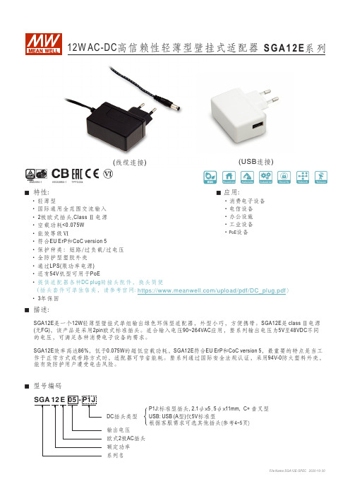
■ 特性:‧轻薄型‧国际通用全范围交流输入‧ 2极欧式插头,Class Ⅱ电源‧空载功耗<0.075W‧能效等级Ⅵ‧符合EU ErP 和CoC version 5‧保护种类:短路/过负载/过电压‧全防护型塑胶外壳‧通过LPS(限功率电源)‧还有54V 机型可用于PoE‧提供适配器各种DC plug 转接头配件,换头简便(插头套件可单独售卖,请参考官网: )‧ 3年保固File Name:SGA12E-SPEC 2020-10-30‧消费电子设备‧电信设备‧办公设施‧工业设备‧PoE 设备■ 应用:系列名额定功率欧式2极AC 插头输出电压DC 插头类型{■ 描述:■ 型号编码P1J:标准型插头, 2.1ψ×5.5ψ×11mm, C+ 音叉型根据客服需求可选其他插头(参考4~5页)USB: USB (A 型)仅5V 标准型SGA12E 是一个12W 轻薄型壁挂式单组输出绿色环保型适配器,外型小巧,方便携带。
SGA12E 是 class Ⅱ电源(无FG),该产品是采用2pin 欧式标准插头。
适合输入电压90~264VAC 应用,整系列输出电压为5V 至48VDC 不同的电压,可满足各种消费电子设备的需求。
SGA12E 效率高达86%,低于0.075W 的超低空载功耗,SGA12E 符合和,最重要的特点是当工EU ErP CoC version 5作于正常方式或旁路方式时,适配器可节省能耗。
整系列通过国际安全法规认证,采用94V-0防火塑料外壳,能有效防护用户遭受电击风险。
(线缆连接)(USB 连接)快速转接头范例:Min. DIN 3 Pin with Lock ( Min. DIN 4 Pin with Lock (。
MTL5500模块AC电源适配器MPA5500及配套配件PCL45USB的说明书

The given data is only intended as a product description and should not be regarded as a legal warranty of properties or guarantee.In the interest of further technical developments, we reserve the right to make design changes.The MPA5500 enables any MTL5500 module that is normally powered from a nominal 24V DC supply (i.e. those that are not loop-powered) to be powered from a high-voltage AC supply.It plugs into the power socket (terminals 13 and 14) of an MTL5500 module and clips securely onto the module housing. The 25V DC power output from the adaptor is sufficient to supply a single module and can be connected to any normal AC power source.MPA5500MPA5500SPECIFICATIONInput voltage85 – 265V AC, (45–65Hz)Efficiency71% typ. at 230V ACPower dissipation1.2W typ at 230V AC.Input terminalsCage-clamp terminals accommodating conductors upto 1.5mm 2stranded or 16AWG single-core Input protectioninternal fuse, not user serviceable Output voltage25Vdc ± 10%Output current120mA at 25VAmbient temperatureOperating: –20 to +60°C Storage: –40 to +80°C MountingPlugs into and clips onto MTL5500 range I/O moduleIt is not for use with any equipment other than MTL5500.Humidity5 to 95% relative humidity MechanicalIngress Protection: IP20Material: polycarbonate Weight: 28g approx.Standards complianceEN 61326, EN 61010SPECIFICATIONPCL45USB hardware LocationSafe area ConnectionsPC side: USB B(F) socketConverter side: cable with 3.5mm jackplug, 3-pole for MTL4500 and MTL5500 range of converters. An adapter cable is provided for other earlier MTL converters.Cable lengthsConverter side (fitted): 1.5mUSB cable A(M) to B(M) (supplied): 2m Ambient temperature limits–10°C to +60°C operating –20°C to +70°C storage Humidity5 to 95% relative humidity (non-condensing)Weight200gPCS45 Configuration softwareCompatible with Windows XP, Win7, Win8.Consult MTL for operation with any other operating system.Software mediumPCS45 supplied on CDUpdates are available at Recommended minimum PC configurationMicrosoft Windows XP, Win7, Win820MB of available hard disc space CD ROM driveAvailable USB portPrinter (local or network)The PCS45/PCL45USB configurator allows MTL converters to be configured from a standard PC running a Microsoft® Windows® operating system. It comprises PC software, provided on a CD (PCS45), and an ATEX certified interfacing link (PCL45USB). Converters can be configured from the safe area, while on-line, and configurations can be saved to disk and printed out when required. It is suitable for use with MTL4000, MTL4500, MTL5000 and MTL5500 range of products.The given data is only intended as a product description and should not be regarded as a legal warranty of properties or guarantee.In the interest of further technical developments, we reserve the right to make design changes.SPECIFICATION See also common specificationAC input range85Vac to 264Vac, 47 to 63Hz DC input range120Vdc to 375Vdc DC output24V (adjustable 24-28V) Output current2.5A (3,75A for 5s)Main interruption holdup time >20ms Efficiency90%Input to Output isolation 4kVacIsolation Input/output to ground 1.5kV a cHousing material AluminiumDimensions L x W x H 121 x 32 x 125mm Weight 370g Wire size0.3 to 3.3mm 2, AWG 22-12 with removable terminals Operating Temperature -20°C to +80°C Storage Temperature -25°C to +85°CSPECIFICATIONAvailable in 4 different lengths:PB - 8T = 8 connectors and loops PB - 16T = 16 connectors and loops PB - 24T = 24 connectors and loops PB - 32T = 32 connectors and loops Insulation material :PVCConductor :24 strands of 0.2mm dia (0.75mm 2) standard copper Insulation thickness :0.5 to 0.8 mm Current rating :12A maxOperating temperature range :–20ºC to +60ºCMax voltage drop on 32 modules drawing 130mA max :0.5VCHOOSING A POWERBUS KITChoose a powerbus where the number of power plugs is greater than or equal to the number of isolators to be powered and if necessary cut the powerbus to the required number of terminations.Note: To reduce the risk of excessive voltage drop or overcurrent do not connectpowerbuses in series.A general purpose 24V dc power supply for use with MTL isolator and barrier product ranges. Single 24V output with adjustable voltage and status indication.For mounting on 35mm top hat DIN rail.(replacement for MTL5991)The given data is only intended as a product description and should not be regarded as a legal warranty of properties or guarantee.In the interest of further technical developments, we reserve the right to make design changes.SPECIFICATIONConstructionGlass reinforced polycarbonate base - DX070Glass reinforced polyester base - DX170Transparent polycarbonate lid ProtectionDust-tight and water-jet proof to IEC529:IP65Lid fixingCaptive fixing screwsWeight (excluding barriers/isolators) kgDX070 0.8DX170 2.6Items providedDIN rail - fittedETL7000 Earth terminals (2 x) - fitted "Take care IS" front adhesive label Cable trunking (DX170 only)Note: Isolators are not included.MountingWall fixing lugs provided. For further details refer to INM5500.Tagging and earth railAccommodates MTL5500 range of accessories.Permitted locationSafe (non-hazardous) areaDIMENSIONS (mm) AND MOUNTINGNote: N. America/Canada - E nclosures are rated NE MA 4X so can be used in Class 1, Division 2 (gases) location, but check with local requirements and ensure all cable entries also conform. Additional warning label will be required on or near the enclosure, see installation details. Not suitable for Class II or III, Division 2 hazardous locations.Approximate capacities (on DIN rail between earth terminals)Number of MTL5500 isolatorsDX0704(2)*DX17010(8)** Use these figures when IMB57 mounting blocks for tagging/earth are included.Ambient temperature limitsDependent on units fitted. See instruction manual INM5500.DX170The given data is only intended as a product description and should not be regarded as a legal warranty of properties or guarantee.In the interest of further technical developments, we reserve the right to make design changes.MTL5500 range of isolators mount quickly and easily onto standard DIN rail. A comprehensive range of accessories simplifies earthing and tagging arrangements.Type AType BTH5000DIN-railSee also‘MTL5500 range of powerbus kits'MOUNTINGTHR2 DIN rail,1m lengthDIN rail to EN50022; BS5584; DIN46277MS010 DIN rail module spacer, 10mm, pack of 5Grey spacer, one required between each MTL5533 or MTL5995-PS and any adjacent module on a DIN rail, to provide 10mm air-circulation space between modulesEARTH RAILS AND TAG STRIPIMB57 Insulating mounting blockOne required at each end of a tagging strip/earth rail. Suitable for low-profile (7.5mm) and high-profile (15mm) symmetrical DIN rail.ETM7 Earth terminal, bag of 50For terminating cable screens and 0V returns on the ERL7earth rail. For cables ≤ 4mm 2. Exact dimension dependent on manufacturer.TAG57 Tagging strip, 1m lengthCut to size. Supplied with tagging strip label suitable for MTL5000 or MTL5500 modules.TGL57 Tagging strip labels, set of 10 x 0.5mSpares replacement, for use with TAG57 tagging strip. Suitable for MTL5000 or MTL5500 modules.INDIVIDUAL ISOLATOR IDENTIFICATIONTH5000 tag holdersEach isolator may be fitted with a clear plastic tag holder, as shown below. Order TH5000, pack of 20.CONNECTORSEach MTL5500 unit is supplied with signal and power connectors, as applicable.Spares replacement connectors are available separately; see ordering information.ERB57S Earth-rail bracket, straightNickel-plated; supplied with two push fasteners, one (14mm,35mm 2) earth-rail clamp and one (10mm, 16mm 2) earth clamp.ERL7 Earth rail, 1m lengthNickel-plated; may be cut to length.warranty of properties or guarantee.In the interest of further technical developments, we reserve the right to make design changes.• Total flexibility • Special functions • Reduce wiring • Signal conditioning • Simplify installation• HART® integrationABB AutomationS100, INFI90, S800EmersonDelta V, M Series, S Series GE Bently-Nevada HIMAHIMaxHoneywellPMIO, C200, C300, UPIO, Safety Manager, USIO Rockwell AutomationICS Triplex, PlantguardSchneider ElectricFoxboro I/A, Triconex Trident/Tricon, Modicon SiemensET200, S7YokogawaCentum R3, VP, Prosafe RS, CS3000The MTL4500/MTL4600 range of backplanes, enclosures and other accessories provide comprehensive, flexible and remarkably compact mounting facilities for system vendors, original equipment manufacturers and end users alike.CUSTOMISED BACKPLANESEaton provides a complete design and manufacturing service for MTL customised backplanes. Customised backplanes give the vendors and users of process control and safety systems the opportunity to integrate MTL4500/MTL4600/HART® modules directly into their system architecture. As there are no hazardous-area circuits on the backplanes, customised versions can be produced without the need for IS certification, so simplifying design and lowering costs.UNIVERSAL CUSTOM BACKPLANESThe 'universal' backplane allows a fast and economic approach to providing a custom interface. Where tight time schedules exist, the backplane can be installed to allow the panel building and wiring to be completed. The customised adapter card can then be plugged in at any time up to integrated test.ADAPTER CARDSAdapter cards already exist for many of the DCS companies. In addition there is a range of general purpose cards that offer reduced wiring for use with specific MTL modules. These are also available in left- and right-hand versions to ease panel wiring.STANDARD MTL BACKPLANESStandard MTL backplanes are available to accommodate 4, 8, 16, or 24 modules using screw-clamp connectors for the safe-area circuits. On an individual backplane, any module can be plugged into any position and module types can be mixed. For 8-, 16- and 24-way backplanes, screw-clamp connectors which plug into the backplanes provide primary and secondary 24V dc power supplies. Power to several 8- or 16-way backplanes can be interconnected to reduce and simplify wiring – see instruction manual INM4500/INM4600 for details.OPTIONAL ACCESSORIESOptional accessories include colour coded tagging strip kits for all three sizes of backplane and earth rail kits for 8 and 16-way versions. Mounting accessories are available for surface (all backplanes), T-section and G-section DIN-rail (8- and 16-way versions), and a horizontal plate for mounting 24-way backplanes in 19-inch racks.WEATHERPROOF ENCLOSURESWeatherproof enclosures are available for applications where separate safe–area enclosures are required for backplanes with modules. Available to accommodate one 4-way or one 8-way backplane, they are manufactured from GRP giving protection against dust and water to IE C529:IP65. The lids are made from transparent high-strength polycarbonate so that LEDs, switches, etc, on the tops of the modules are easy to see.MTL CPS STANDARD BACKPLANESDCS VENDORS/SYSTEMS SUPPORTED:The given data is only intended as a product description and should not be regarded as a legal warranty of properties or guarantee.In the interest of further technical developments, we reserve the right to make design changes.CPS16CPS08CPS24CPS04CPS BACKPLANE DIMENSIONS (mm)Power requirements, Vs21V dc to 35V dc through plug-in connectors Safe–area connectionsCPS: 2.5mm 2screw-clamp terminals – 6 positions per module Weight (without modules or accessories)CPS04: 96g CPS08: 225g CPS16: 419g CPS24: 592gBACKPLANE ACCESSORIESCPS04 CPS04-CCCPS08 CPS08-CCCPS16 CPS16-CCCPS24SCK45 - backplane clips10 x strip of four16 x strip of twoMCK45 - backplane clipsHMP24 - 19" RACK MOUNTING PLATE FOR CPS24-CC - Conformal CoatingThe given data is only intended as a product description and should not be regarded as a legal warranty of properties or guarantee.In the interest of further technical developments, we reserve the right to make design changes.MTL4500 range of backplanes can be customised for specific applications and customer’s requirements. All the signals on the backplane are ‘safe-area’ so custom designs are possible without the need for certification. Eaton offers a fast and efficient customising service upon request.Many installations can benefit from the use of existing custom solutions. These provide reduced system wiring, modularisation of the channels to match the IO card. In addition diagnostics, such and line fault detection, can be grouped prior to connection into the system.Remote cable connections:In addition to the many DCS solutions, listed on a previous page, are backplanes and cables that are ideal when the isolators are mounted in remote cabinets and the signals need to be returned to the system via a multicore cable.CP-DYN RANGEFTASize FunctionMTL modules CP-DYNB-AIOB16ch analogue input /output MTL4541, 4546Y, 4573CP-DYNB-AI250 B 16ch analogue input 1-5V o/p MTL4541, 4573CP-DYNA-2AIO A 16ch analogue input / output MTL4544, 4549Y CP-DYNB-DI B 16ch digital inputMTL4511, 4514CP-DYNB-DILF B 16ch digital input with LFD MTL4514CP-DYNB-2DI B 32ch digital input MTL4513, 4516, 4517CP-DYNB-4DI B 48ch digital input MTL4510CP-DYNA-DO A 8ch digital output MTL4521, 4521L CP-DYNB-DOB16ch digital outputMTL4521, MTL4521LCABLESAll FTAs use the Tyco 20 pin Dynamic range of connectors. Cables are fitted with a mating connector and free ends the other, for connection to the system card.Cable ordering codeCABDYN20-0.50.5m cable CABDYN20-1 1.0m CABDYN20-2 2.0m CABDYN20-3 3.0m CABDYN20-5 5.0m CABDYN20-8 8.0m CABDYN20-10 10m CABDYN20-15 15m CABDYN20-20 20m CABDYN20-25 25m CABDYN20-30 30mDESCRIPTIONFor use when the IS interfaces are remotely mounted from the control system, this series of cable connected FTAs provide a simple plug/socket connection method for IS field devices to any control system. The FTAs come fitted with mounting pillars for surface mounting or may be used with the DIN rail mounting kit to mount on a single DIN rail.The cable connections between the system card and the FTA use the Tyco Dynamic range of connector which provide a reliable and high density solution.CP-DYN DIMENSIONSFor full technical details please contact you local Eaton sales office.The given data is only intended as a product description and should not be regarded as a legal warranty of properties or guarantee.In the interest of further technical developments, we reserve the right to make design changes.ANALOGUE SIGNAL REPEATCPS04-AIRE P backplane may be used to generate a repeat output from a single transmitter source. This includes high integrity loops in general purpose applications. The MTL4641 is used to generate an isolated repeat signal from an existing 4-20mA loop.CPS04-2AIO, 8 channel backplane, is used with IS signals with 2 channel AI or AO modules or with the MTL4544D to generate 4 inputs with repeat outputs.MTL CUSTOM BACKPLANE SOLUTIONSA wide range of backplanes can be offered with application specific functions. System connection options and modularity for individual signal types can be provided to offer significant space and cost savings. Please contact your local Eaton sales office if you wish to discuss your application requirements.PRODUCT MIGRATIONMigration options for legacy MTL4000 range installations are also available. This enables isolators to be easily upgraded, or re-connecting existing isolators to a new control system, with the minimum of disturbance to existing wiring. For more information on product migrationvisit the resource section at CPELCO RANGEA range of dedicated backplanes to interface with MTL4500 range of intrinsically safe isolator modules and the MTL HART maintenance system products. The backplanes offer a standard Elco interface connector for use in systems where the IS interfaces are remote from the DCS.Backplane Function MTL moduleCable CPM08-2AIO 16ch AI 4-20mA MTL4544/4576/4549Y x 8 Elco38 x 1CPM08-2AV 16ch AI 1-5V MTL4544/4576 x 8 Elco38 x 1CPM16-AIO 16ch AIO 4-20mA MTL4541/4573/4546Y Elco38 x 1CPM16-2AIO 32ch AI 4-20mA MTL4544/4576/4549Y x 16 Elco38 x 2CPM16-2AV 32ch AI 1-5V MTL4544/4576 x 16 Elco38 x 2CPM08-DDI 16ch DI MTL4513/4516 Elco38 x 1CPM16-DO 16ch DO MTL4524/4523RElco38 x 1CGM08-DO8ch DOMTL4521/4521L (loop powered)Elco38 x 1For full technical details please contact your local MTL sales office.ORDERING INFORMATIONPlease go to our website at for the latest information regarding safety approvals, certificates and entity parameters.。
NCP1271D65R2G 笔记本适配器AC-DC电源管理芯片

NCP1271
Soft-Skipt Mode Standby PWM Controller with Adjustable Skip Level and External Latch
The NCP1271 represents a new, pin to pin compatible, generation of the successful 7−pin current mode NCP12XX product series. The controller allows for excellent stand by power consumption by use of its adjustable Soft−Skip mode and integrated high voltage startup FET. This proprietary Soft−Skip also dramatically reduces the risk of acoustic noise. This allows the use of inexpensive transformers and capacitors in the clamping network. Internal frequency jittering, ramp compensation, timer−based fault detection and a latch input make this controller an excellent candidate for converters where ruggedness and component cost are the key constraints.
12V2A电源适配器

基于PT2202的24W AC-DC开关电源基本特性电流控制模式的反激式开关变换器交流90~264V,50~60Hz工作范围平均效率和待机功耗均超过能源之星V5.0标准自动恢复的过流及负载短路保护功能自动恢复的输出过压保护工作环境温度0~40℃,湿度20%~80%电原理图和实物照片电路如图1,交流侧输入有2A保险丝F1和抗浪涌负温度系数热敏电阻NTC1。
CX1和FL2组成差共模EMI滤波器,BD1是全桥整流器,C1为高压母线电容。
T1,Q1,D51组成反激式电路架构,U1为电流控制型PWM控制IC。
当接通交流市电,母线电压经由R3,R4为IC PT2202提供启动电流,当VCC电压达到芯片启动电压,芯片开始工作,随着输出电压的上升,当变压器辅助绕组正向电压超过芯片最低工作电压时,芯片供电电流开始主要由变压器辅助绕组供电。
二次侧芯片TL431提供反馈电压比较基准2.5V以及误差放大信号,经由光耦隔离放大,产生原边的反馈控制信号FB,作为电流内环的一个比较基准,控制原边MOS管的峰值电流,实现输出的恒压控制。
R7,R8用于设置MOS管最大峰值电流,实现限功率控制。
图1 电原理图图2是电源的实物照片,45个元件安装在70×42.5×25mm的环氧单面印制板上,PCB走线按照电力电子规范要求设计。
图2 实物照片电气参数和BOM电源主要电气参数如表1所示,表中开关频率为最高工作频率,满载测试条件。
在全电压输入范围内,实现额定功率24W输出,实际最大输出功率超过30W。
表2是详细的材料清单,为了保证质量,尽量选用推荐产商的元器件。
表1:电气参数表表2:材料清单序号元件名称型号厂商1 BD1 整流桥KBP206 PAN JIT2 C1 铝电解电容47uF/400V NICHICON3 C2 陶瓷电容2200pF/1KV AVX4 C31 陶瓷电容1uF/25V AVX5 C32 陶瓷电容22pF/50V AVX6 C33 铝电解电容22uF/50V NCC7 C51 陶瓷电容1000pF/1KV AVX8 C52 铝电解电容680uF/25V NCC9 C53 陶瓷电容100nF/25V AVX10 CX1 X 电容0.22uF/275V HUA JUNG11 CY1 Y 电容4700pF/250V MURATA12 D1 快速恢复二极管BYV26C VISHAY13 D31 快速恢复二极管FR107 VISHAY14 D51 肖特基二极管STPS41H100CT ST15 D52 发光二极管LED_0 EVERLIGHT16 F1 保险丝 2.5A/250V Cooper17 FL2 共模电感16mH18 Q1 功率场效应管FQP8N60 INFINEON19 R1,R2 SMD电阻1M(1206)TY-OHM20 R3,R4 SMD电阻560K(1206)TY-OHM27 R32 SMD电阻100K(0805)TY-OHM24 R33 SMD电阻47R(0805)TY-OHM25 R34 SMD电阻100R(0805)TY-OHM26 R35 SMD电阻0R(1206)TY-OHM21 R5,R6 SMD电阻200K(1206)TY-OHM28 R51 SMD电阻100R(1206)TY-OHM29 R52,R54 SMD电阻10K(0805)TY-OHM30 R53 SMD电阻1k(0805)TY-OHM31 R55 SMD电阻36K(0805)TY-OHM32 R56 SMD电阻9.1K(0805)TY-OHM22 R7 SMD电阻 6.2 1%(1206)TY-OHM23 R8 SMD电阻1R 1%(1206)TY-OHM33 NTC1 热敏电阻5ohm GE Infrastructure34 T3 变压器EI28 Crpowtech35 U1 控制芯片PT4201 Crpowtech36 U2 光耦PC817 VISHAY37 U3 稳压三极管TL431 ON工作波形1.稳态输出电压,纹波电压图3,图4分别为输入100Vac,输出为满载时输出电压波形和纹波电压波形。
AV6471快速操作手册
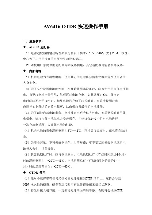
A V6416 OTDR快速操作手册一.注意事项:◆ AC/DC 适配器(1)电源适配器的输出特性必须符合以下要求:15V~20V,大于2.5A,极性:中心为正。
使用过高的电压会引起设备损坏。
(2)请使用厂家提供的适配器为本仪器供电,其它适配器可能会损坏仪器。
◆ 内部电池(1)机内电池为专用锂电池,使用其它的电池将会损害仪器并危及使用者的人身安全。
(2)为了充分发挥电池的性能,在开始使用本设备时,应首先使用内部电池供电,直至将电池电量用尽,然后再对电池充电,如此循环2-3次,首次充电时间应不小于10小时。
如果电池已存储了较长时间,在首次使用时也应进行如上所述的充放电循环,以确保获得最佳的电池性能。
(3)为了延长内部电池寿命,电池被充电后应移去外电,如需要长时间用外电供电,请将内部电池取出并妥善保存,并建议每2~3个月对电池进行一次充放电循环,以确保电池的性能。
(4)机内电池的充电温度范围为5℃~45℃,环境温度过高时,充电将自动终止。
(5)为安全起见,不可拆解电池包,以防短路;更不要猛烈撞击电池或将电池投入火中,以防爆炸。
(6)仪器长期贮存时,应将电池取出。
电池长期贮存(存储时间超过6个月)时的温度范围为:-20℃~45℃。
电池短期贮存(存储时间小于等于6 个月)时的温度范围为:-20℃~60℃。
◆ OTDR 使用(1)绝对不能将带有任何光信号的光纤连接到OTDR 端口上,这样会导致OTDR 永久性的损伤,确保在连接时所有光纤都是在无信号状态下。
(2)将光纤接入端口前,一定要将光纤端面清洁干净,否则将会导致OTDR测试误差。
(3)必须保持OTDR 光输出连接器内部的清洁,避免油膏等污物污染光输出 连接器,否则将导致OTDR 无法测试出光纤曲线。
维护与保养(1)仪器贮存时,环境温度范围应为-20℃~60℃(这里仅对仪器主机而言, 电池的贮存详见内部电池的说明),保持通风干燥,无日光直晒。
仪器长 时间不用时,请将仪器内部电池取出,并请定期通电检查,同时定期对 电池进行充放电循环。
能源之星电源适配器技术要求
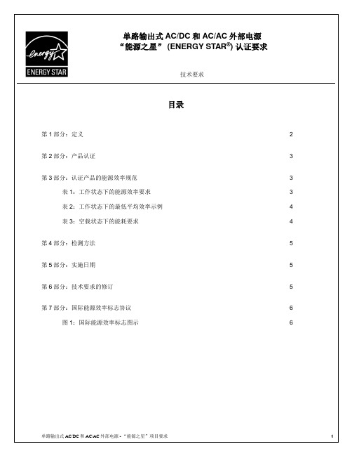
第1部分:定义
以下是符合“能源之星”标准的单路输出式
造商生产的外部电源产品,只有符合所有这些标准,才能取得“能源之星”认证。
1) 定义:
源型号。
针对这一目的以及本文第四部分所述的检测方法,美国环保局已对单路输出式AC/AC
制造商使用该标志时,必须符合以下特征:
罗马数字: I、II、III、IV、V或VI。
Times Roman字体(或其它 plain serif字体)。
清晰且不易擦除。
文字颜色与铭牌背景色反差要大。
位于电源铭牌上,在铭牌上的具体位置由制造商自行决定。
“效率等级”字样可有
任何符合III级或以上等级要求的外部电源都可通过“能源之星”认证。
而性能等。
- 1、下载文档前请自行甄别文档内容的完整性,平台不提供额外的编辑、内容补充、找答案等附加服务。
- 2、"仅部分预览"的文档,不可在线预览部分如存在完整性等问题,可反馈申请退款(可完整预览的文档不适用该条件!)。
- 3、如文档侵犯您的权益,请联系客服反馈,我们会尽快为您处理(人工客服工作时间:9:00-18:30)。
AC-DC电源适配器
一、AC-DC电源适配器的含义:
AC-DC电源适配器是电源系列产品中最简单的电源,它主要由电源变压器、整流电路、滤波电路组成,有些AC-DC 电源适配器带有稳压电路。
二、AC-DC电源适配器的工作原理:参照下图加以说明!
AC-DC电源适配器的工作原理是:电源变压器将交流市电转换成所需的交流电压(36V以下),经过整流电路后,再经过滤波电路得到波形比较平顺的直流电压。
一般的AC/DC电源适配器就做到此步就行了,再配上电源插头、DC电源线、外壳就可以使用了;如果需要稳定的DC电压输出,那就需要稳压电路了。
三、各部分电路设计:
1、电源变压器的设计:下面以“变压器设计大师”软件加以说明!
⑴、打开“变压器设计大师”软件,显示画面如下:
⑵、点击左下角的“设计指导”按钮,会弹出以下对话框:
⑶、按“下一步”按钮,会弹出以下对话框:
⑷、“初级绕组电压”是固定的220.00V(注册后才可变更此参数);“次级绕组个数”有“一组”到“六组”可供
选择,用鼠标点击“”按钮,根据自己需要的实际情况作出“几组”的选择;“硅钢磁感应强度”有“中强度”/
“低强度”供选择,用鼠标点击“”按钮,选择磁感应的强度类型,一般情况下选“中强度”。
选择好后,按“下一步”按钮,出现下面的画面:
⑸、用鼠标点击“绕组数据”下面的“第[1]次级。
如果有几个次级,在完成下面的步骤后,再用鼠标点击“绕组数据”下面的“第[N]次级。
①、在“输出电流(A)”后面的框内填好需要的电流值,再在“输出电压(V)”后面的框内填好需要的电压值。
例如:“输出电流(A)”填:2,就表示是输出电流为2A;“输出电压(V)”填:12,就表示是输出电压为12V。
②、在“负载类型”后面的框内选择类型,有“电阻性”/“电容性”/“电感性”三种选择,用鼠标点击“”
按钮作出选择,一般情况下选择“电阻性”;再在“整流方式”后面的框内选择方式,有“半波整流”/“全波整流”/
“桥式整流”/“倍压整流”/“没有整流”五种方式供选择,用鼠标点击“”按钮作出选择,一般情况下选择“桥
式整流”。
选择好后,按“更新数据”按钮,出现下面的画面:
⑹、按“下一步”按钮,出现下面的画面:
⑺、按“完成”按钮,出现下面的画面:
⑻、上图中是“”,用鼠标点击“”出现以下画面:
⑼、上图中的铁芯尺寸一目了然,用鼠标点击“”出现以下画面:
这样一来,这个输入AC220V、输出AC12V/2A的电源变压器就设计好啦!
如果要设计两个(或以上)的次级绕组电源变压器,在上面第⑷步中用鼠标点击“次级绕组个数”框内的“”
按钮,选择“二组”即可;
备注:此软件一定在注册以后才能设计两个(或以上)的次级绕组电源变压器!!此软件请到本网站的“资料下载中心”下载!!然后再去注册即可正常使用。
2、整流滤波电路的设计:
上图中:“”为电源变压器;“”为桥式整流电路,由4个二极管组成,一般选择1N4001~1N4007就可以了,
具体参数请参照下表!滤波电路由“、”构成,“”为电解电容,只要空间允许,尽量选用容量大一些的,
电压最好为桥式整流后的1.5倍,“”为瓷片电容,容量一般为0.1uF,电压超过桥式整流后的1.5倍即可。
表1:1N400系列整流二极管的参数表
3、稳压电路的设计:AC-DC电源适配器的稳压电路,一般都相当简单,下面简要介绍几种稳压电路!
⑴、晶体管并联稳压电源:参照下图说明!
T1是调整管、D1是基准稳压管,R1是D1的限流电阻,R2是限流电阻,R3是负载。
这个稳压电路的输出电压约等于稳压管D1的稳压值(实际上要加上T1发射结电压,一般锗管取0.3V,硅管取0.7V)。
这是由于电源在工作时,T1发射结导通,发射极电压与基极电压保持一致,而基极电压被D1稳定在一个固定值。
这个电路可以看作T1将D1的稳压作用放大了β倍,相当于接入一个稳压值为D1稳压值,稳压效果为β倍D1稳压效果的稳压管。
⑵、晶体管串联稳压电源:参照下图说明!
T1是调整管,D1是基准电压源,R1是限流电阻,R2是负载。
由于T1基极电压被D1固定在U D1,T1发射结电压(U T1)BE在T1正常工作时基本是一个固定值(一般硅管为0.7V,锗管为0.3V),所以输出电压U O=U D1-(U T1)BE。
当输出电压远大于T1发射结电压时,可以忽略(U T1)BE,则U O≈U D1。
⑶、复合管并联稳压电源:参照下图说明!
这种使用复合调整管的并联稳压电源,既可以得到较大的β值,又能够有较大的I CM。
元件选择时可采用,但是由于这个电路的电流较大,要注意限流电阻R1选择时除考虑阻值外还要考虑其功率,以免负载断路时烧坏限流电阻。
⑷、串联负反馈稳压电源:参照下图说明!
串联负反馈稳压电路电路图,其中T1是调整管,D1和R2组成基准电压,T2为比较放大器,R3~R5组成取样电路,R6是负载。
⑸、采用W7815稳压IC的稳压电路:参照下图说明!
输入电压“Ui”经“C1”滤波后进入稳压IC W7815的第1脚,从3脚输出15V直流电压,再经“C2”滤波,从“Uo”两端输出。
⑹、采用LM317稳压IC的稳压电路:参照下图说明!
输入电压“Vi”经“C1”滤波后进入稳压IC LM317的第3脚,从2脚输出1.2-20V直流电压,1脚与2脚之间接1个电阻,再接1个半可调电阻,可以调节输出电压的电压值,再从“Vo”两端输出。
☆稳压电路及稳压IC都很多,在此就不作详细介绍,实际应用时可以根据自己的需要选择稳压电路及IC☆
四、AC-DC电源适配器的整体结构: 下面以一个AC220V输入/DC9V 500mA输出的AC-DC电源适配器加以说明!
1、下图是AC-DC电源适配器的内部组成部分:
2、下图是AC-DC电源适配器的整体外观图:
五、AC-DC电源适配器的发展方向:
随着金属的价格猛涨,绕制电源变压器的铜芯线变得越来越贵,再加上其本身的转换效率也不高,在今后的市场份额会越来越低,逐渐会被开关电源所替代!。