机构HMB介绍
10.Hmb和Dmb氨基酸

的活性羰基,一般多肽序列连接当中,大多用Hmb氨
基酸是因为Hmb基团上含有的活性羰基,其酰基转移
机制使得Hmb氨基酸后面一个氨基酸的连接难度大大
降。而Dmb因为没有这个活性羰基,而且Dmb基团
的存在使得该氨基酸的空间位阻大大增加,所以其后
面一个氨基酸连接难度会有所相应提高。
但对于一些要求合成后酰化或磷酸化的肽链,
(ⅣⅡ)
Ⅰ:Ac2O( 10eq )Ⅱ:95%TFA Ⅲ: Ac2O( 10eq ) DIPEA ( 10eq ) Ⅳ:20%哌啶/DMF Ⅴ: Boc2O ( 10eq )
H2N Resin 20%哌啶
(Fmoc-NH-CHR-CO)2O 酰基转移 OCH 3
OCH 3
Fmoc -NH -CHR -CO
O
NH CHR CO NH Resin
OH
OC CHR NH Fmoc
N
CHR CO NH Resin
Dmb与Hmb氨基酸的差别
Dmb与Hmb基团的差距就在与其苯环上有无潜在
2.彻底消除D-G重排现象
D-G重排是因为Gly上面的酰胺氢与Asp侧链上的羧基结合从 而导致的,而当插入Hmb取代酰胺氢之后,也就终止了与Asp侧 链结合的可能,故而它可以彻底消除D-G重排的现象。
3.可能对片段间的连接有促进作用
4.减少环化过程中低聚物和循环二聚体 的形成
Hmb氨基酸参与的反应过程
Hmb和Dmb氨基酸
Hmb和Dmb氨基酸的基本结构
OCH 3
Fmoc O
Fmoc
N
CHR
COOH
Hmb氨基酸
OCH 3
液压弹簧机构简介

液压弹簧机构
5 2019/9/18
液压弹簧机构的发展
图1 机构使用量统计表
液压弹簧机构
6 2019/9/18
液压弹簧机构AHMA-HMB与断路器的匹配(1)
液压弹簧机构
7 2019/9/18
液压弹簧机构AHMA-HMB与断路器的匹配(2)
液压弹簧机构
8 2019/9/18
AHMA8.1的技术参数
重量:482kg 外形尺寸:620mm×890mm(高) 传动杆行程:205mm 传动杆活塞直径:42mm 传动杆直径:25mm 储能活塞直径:115mm 储能活塞行程:59.5mm 合闸消耗:11mm 分闸消耗:19mm
液压弹簧机构
25 2019/9/18
AHMA4.3的弹簧参数
弹簧类型:碟形弹簧 数量:8片 排列方式:简单交替 尺寸:Φ485mm×Φ163mm×14.25mm
液压弹簧机构
26 2019/9/18
AHMA8.1的弹簧参数
弹簧类型:碟形弹簧 数量:12片 排列方式:双层交替 尺寸:Φ550mm×Φ200mm×15.5mm
液压弹簧机构
27 2019/9/18
AHMA4.3行程曲线(行程与压力的关系)
液压弹簧机构
28 2019/9/18
AHMA8.1行程曲线(行程与压力的关系)
液压弹簧机构
29 2019/9/18
AHMA4/8的储能指示
液压弹簧机构
30 2019/9/18
液压油
允许使用的液压油:
Aeroshell(壳牌)Fluid 4或 ESSO(埃索)Unis J13, 两种油 可以混合使用。
GIS电站HMB8液压弹簧操动机构安装使用说明书

1
识别号 序列号
1-标牌
图 1.5-1:铭牌
4
ZF15-550 安装使用说明书
NHVS 新东北电气集团高压开关有限公司
2.1 HMB–4/-8 操动机构的设计
2.1.1 操动机构组成模块 模型设计和 HMB-4 和 HMB-8 操动机构的主要组成见表 2.1-1,表 2.1-2,表 2.1-3。 模型是: l 动力模块 l 储能模块 l 工作模块 l 控制模块 l 监视模块
3.3 安装
断路器的装配应该依据断路器生产厂家的说明来完成。
注意
通过校正或采取必要的设计结构必须避免作用在活塞杆的横向压力。通常地,活塞杆作用在
一个滑动衬套,或者通过拐臂作用在转轴上。对后者应采用线性导向结构。
3.4 投入运行
断路器的投运报告中要填写有关操动机构的投运记录。 投运之前要按照第 4.3 节的规定对操动机构做目视检查。 全部调整已经准备工厂制造和安装,因此投运时无须做新的调整。投运时,要把碟簧柱储能,并连 动断路器一起多次进行手动合分闸操作。同时应该检查弹簧行程开关和辅助开关的监视功能。 投运准备工作完成后,正式投运之前要进行功能试验。维修工作完毕后也应该进行功能试验(见第 4.3 节)。功能测试只有在跟高压电网断开,至少在 SF6 室有闭锁压力和碟簧柱必须储能才能执行。 注意 投运之前,应该检查储能活塞对中心孔和中心环的的位置,必要时加以纠正。
1.1.2 版权
我们保留全部权利在这份文件和其中的内容,未经允许,复印、使用和泄露给第三方都是 严厉禁止的。
1.2 安全规程
下面的注意是针对个人的安全和避免损坏安装和连接组件,有关部门上司必须确保全部的
下属完全理解这些提示。
— 安全规程在文件中标记为“信号字”。
252kV HGIS液压机构)
252kV H-GIS六氟化硫复合电器西安西电开关电气有限公司252kV H-GIS六氟化硫复合电器产品介绍1、概述目前我国252kV高压开关站主要有两大类:气体绝缘金属封闭开关设备(GIS)、常规敞式开关设备(AIS),近几年又出现了一种新型H-GIS 开关站,其介于全封闭开关设备(GIS)和敞开式开关设备(AIS)之间,是将全封闭开关设备(GIS)八大元件中电压互感器、避雷器及母线采用敞开式设备的一种新型开关站。
这种新型开关站继承了GIS的运行可靠性高、环境适应能力强,耐地震能力强,技术经济指标高的特点。
又可达到标准化、模块化设计和生产,产品可整体运输,、现场安装工作量小,周期短,安装费用低。
另一突出优点是优异的经济性:新型H-GIS开关设备的价格约为GIS产品的80%左右,而其占地面积仅为常规敞开式开关站的45%左右。
西开电气生产的252kV H-GIS是252kV GIS产品技术而派生出的一种新型SF6超高压、大容量SF6气体开关设备,西开电气公司生产的ZF9—252型GIS 是消化吸收日本三菱电机株式会社252kV GIS产品技术而生产的一种新型高压、大容量气体绝缘金属封闭开关设备,,并于1997年通过了两部鉴定。
2002年ZF9-252 用三相机械联动六氟化硫断路器(配气动机构和液压机构)通过了两部鉴定且填补了国内空白。
2004年在荷兰KEMA试验站和国家高压电器质量监督检验中心西安高压电器研究所顺利完成63kA,4000A全套型式试验,63kA,4000A 的252kV GIS(配气动机构和液压机构)填补了国内空白。
ZF9—252型GIS 产品已广泛应用于全国各地,63kA,4000A 的252kV GIS已有31个间隔销往新加坡国家电力公司。
2、使用环境条件安装条件:户内或户外环境温度: -35℃~40℃最大日温差: 25℃相对湿度: 日平均不大于95%;月平均不大于90%。
日照强度(户外) : 0.1W/cm2(晴天中午)最大风压: 34m/s覆冰厚度: 20mm抗震烈度: 水平加速度0.3g;垂直加速度0.15g污秽等级: Ⅰ、Ⅱ、Ⅲ级海拔: 1000m; 2000m; 3000m;3、主要技术参数额定电压: 252kV;额定电流:3150A、4000A;额定频率:50Hz;额定短时耐受电流:50,63kA;额定峰值耐受电流:125,160kA;额定短路持续时间: 3s;额定雷电冲击耐受电压:断路器(对地/断口):1050/1050+206kV,隔离开关(对地/断口):1050/1050+206kV;;额定一分钟工频耐受电压:断路器(对地/断口):460/540kV,隔离开关(对地/断口):460/540kV4、主要技术指标六氟化硫气体零表压下:5min工频耐受(20℃):189kV;在1.1倍最高电压下:晴天夜晚无可见电晕;无线电干扰水平: 在1.1倍最高电压下≤500μV 六氟化硫气体年漏气率: ≤0.5%;六氟化硫气体水分含量: 断路器气室≤150ppmv;其它气室≤250ppmv 机械寿命: 不维修试验5000次;可靠性试验:10000次局部放电: ≤10pc (间隔)5、总体结构252kV H-GIS六氟化硫复合电器由五大元件(断路器、隔离开关、接地开关、电流互感器及终端元件)组成。
浅析HMB-4型液压弹簧操作机构的工作原理及日常运维
浅析HMB-4型液压弹簧操作机构的工作原理及日常运维摘要:电网中断路器液压操作机构可靠性关系到断路器的运行可靠性,乃至电网运行的安全性;HMB-4型液压弹簧操作机构属于维护工作量少,无渗漏,性能优越的操作机构,本文主要对其组成、工作原理、日常运维、常见故障进行简要讲述。
关键词:机构组成;工作原理;运行及维护;故障与处理六氟化硫气体绝缘金属封闭开关设备(GIS)因为其良好的绝缘性能,以及较小的占地空间、较少的维护工作量目前被广泛使用到电厂升压站、变电站,本厂采用西安高压电气研究所电器制造厂生产的ZF1-252型产品,其中断路器液压操作机构采用ABB公司生产的HMB-4型操作机构,运行稳定,可靠性高。
一、HMB-4型操作机构组成(一)机构主要由充压模块、储能模块、工作模块、控制模块、监测模块等组成,如图1所示:图 1 HMB-4液压操作机构机芯外形图1-HMB-4碟簧柱 2-手动泄压阀 3-充油接头 4-活塞杆 5-低压油缸 6-油标7-碟簧柱(非本型号) 8-充压模块 9-油泵电机 10-碳刷 11-储能模块 12-监测模块13-前级换向阀(分闸2) 14-前级换向阀(分闸1) 15-前级换向阀(合闸)16-控制模块(二)液压弹簧操作机构的主要优点:结构紧凑、高可靠性、免维修、磨损极低、内部液压缓冲、工作特性不受温度影响、集成液压回路,不含任何油管、被广泛应用。
二、工作原理(一)操作原理:液压储能缸压缩弹簧进行储能,操作缸进行分合闸操作。
断路器触头的操动力在液压机构里靠差动活塞产生,操动活塞集成在操动机构内。
如图2所示,A1为换向阀轴左端面积,A2为换向阀轴右端面积,A3为换向阀轴右端的面积,其中A3>A2,即分闸;A1+A2>A3,即合闸;图 4合闸操作原理图(二)储能:当机构失压时,行程开关的接点导通,储能电机通电,将油从低压油区泵向高压油区,随着高压油量的增加,高压油推动三个储能活塞运动压缩弹簧,到达预定位置时,行程开关的接点断开,电机停转。
发电机出口断路器HMB-1操作机构说明书
Publication no. 1HDH 418003en Rev.AHydraulic Spring Operating Mechanism Type HMB-1Instructions for Operation and MaintenanceOverviewOverviewInstructions for Operation and Maintenance1General2Product Description3Transportation, Storage, Mounting and Commissioning4Operation and Maintenance5Parts Lists6AppendixHydraulic Spring Operating Mechanism Type HMB-1Contents of the Documentation. . . . . . . . . . . . . . . . . . . . . . . . . . . . . . . . . . . . . . . . . . . . . . . . . . . . .1General1-0. . . . . . . . . . . . . . . . . . . . . . . . . . . . . . . . . . . . . .1.1Please Read This First1-11.1.1Warranty1-1. . . . . . . . . . . . . . . . . . . . . . . . . . . . . . . . . . . . . . . .. . . . . . . . . . . . . . . . . . . . . . . . . . . . . . . . . . . . . . .1.1.2Copyright1-1. . . . . . . . . . . . . . . . . . . . . . . . . . . . . . . . . . . . . . . . .1.2Safety Regulations1-1. . . . . . . . . . . . . . . . . . . . . . . . . . . . . . . . . . .1.2.1General Notes1-2. . . . . . . . . . . . . . . . . . . . . . . . . . . . . . . . . . . . . . . . . . . . . . . . . . . .1.3Validity1-2. . . . . . . . . . . . . . . . . . . . . . . . . .1.4Explanation of the Type Designation1-21.5Nameplate1-3. . . . . . . . . . . . . . . . . . . . . . . . . . . . . . . . . . . . . . . . . . . . . . . .. . . . . . . . . . . . . . . . . . . . . . . . . . . . . . . . . . . . . . . . . .2Product Description2-0. . . . . . . . . . . . . . . . . . .2.1Design of the HMB-1 Operating Mechanism2-1. . .2.1.1Modules of the Operating Mechanism Components2-1. . . . . . . . . . . . . . . . . . . . . . . . . . . . . . . . . . . . .2.1.2Power Pack2-2. . . . .2.1.3Advantages of the Operating Mechanism HMB-12-2. . . . . . . .3Transportation, Storage, Mounting and Commissioning3-0. . . . . . . . . . . . . . . . . . . . . . . . . . . . . . . . . . . . . . . . . . . . .3.1Transportation3-1. . . . . . . . . . . . . . . . . . . . . . . . . . . . . . . . . . . . . . . . . . . . . . . . . . .3.2Storage3-2. . . . . . . . . . . . . . . . . . . . . . . . . . . . . . . . . . . . . .3.2.1Packaging3-2. . . . . . . . . . . . . . . . . . .3.2.2Requirements for Storage Areas3-2. . . . . . . . . . . . . . . . . . . . . . . . . . . . . . . . . . . . . . . . . . . . . . . . . .3.3Mounting3-2. . . . . . . . . . . . . . . . . . . . . . . . . . . . . . . . . . . . . . . . . . . .3.4Commissioning3-3. . . . . . .3.4.1Manually Operating the Operating Mechanism3-3. . . . . . . . . . . . . . . . . . . . . . . .3.4.2Slow Switching Operations3-4. . . . . . . . . . . .3.4.3Deactivating the Close-Position Interlock3-4. . . . . . . . . . . . . . . . . . . . . . . . . . . . . . . . .3.4.4Charging Module3-5. . . . . . . . . . . . . . . . . . . . . . . . . . . . . . .3.5Optional Adjusting Procedures3-6. . . . . . . . . . . . . . . . . . . .3.5.1Adjusting the Operating Speeds3-6. . . . . . . . . . . . . . . . . . . . . . . . . . . . . . . . . . .4Operation and Maintenance4-0. . . . . . . . . . . . . . . . . . . . . . . . . . . . . . . .4.1Instructions for the Operation4-1. . . . . .4.1.1Pump Starts and Checks for Internal Tightness4-1. . . . . . . . . . . . . . . . . . . . . . . . . . . .4.1.2Putting Out of Service4-3. . . . . . . . . . . . . . . . . . . . . . . . . . . . . . . . . . . . . . . .4.1.3Oil Level4-5. . . . . . . . . . . . . . . . . . . . . . . . . . . . . . . . . . . . . . . . . . . .4.2Troubleshooting4-6. . . . . . . . . . . . . . . . . . . . . . . . . . . . . . . . . . . . . . . . . . . . . . . . . . .4.3Checks4-7. . . . . . . . . . . . . . . . . . . . . . . . . . . . . . . . . . . . . . . . . . . . . . . . . .4.4Disposal4-75Parts Lists5-0 . . . . . . . . . . . . . . . . . . . . . . . . . . . . . . . . . . . . . . . . . . . . . . . . . . .. . . . . . . . . . . . . . . . . . . . . . . . . . . . . . . . . . . . . . .5.1Spare Parts, General5-1. . . . . . . . . . . . . . . . . . . . . . . . . . . . . . . . . . . . . . . . . . . . . . . . . . . .6Appendix6-0. . . . . . . . . . . . . . . . . . . . . . . . . . . . . . . . . . . . . . . . . . . . .6.1Technical Data6-1. . . . . . . . . . . . . . . . . . . . . . . . . . . . . . .6.2Tightening Torques for Screws6-2. . . . . . . . . . . . . . . . . . . . . . . . . . . . . . . . . . . . . . . . . . . . . . . . . . . .6.3Utilities6-2. . . . . . . . . . . . . . . . . . . . . . . . . . . . . . . . .6.3.1Cleaning Agents6-2. . . . . . . . . . . . . . . . . . . . . . . . . . . . . . . . . . . . . . .6.4Dimension Diagrams6-3Figure Source List. . . . . . . . . . . . . . . . . . . . . . . . . . . . . . . . . . . . .Figure 1.5-1:Name plate HMB-11-3 Figure 2.1-1:Hydraulic Spring Operating Mechanism Power Pack HMB-1,horizontal2-3. . . . . . . . . . . . . . . . . . . . . . . . . . . . . . . . . . . . . . . . . . . . .Figure 2.1-2:Hydraulic Spring Operating Mechanism Power Pack HMB-1,. . . . . . . . . . . . . . . . . . . . . . . . . . . . . . . . . . . . . . . . . . . . . . .vertical2-4 Figure 3.1-1:Transport Unit Power Pack HMB-1, vertical3-1. . . . . . . . . . . . . . . .. . . . . . . . . . . . . . . . . . . . . . . .Figure 3.4-1:Change-over valve (single-stage)3-3. . . . . . . . . . . . . . . . . . .Figure 3.4-2:Deactivating the close-position interlock3-4. . . . . . . . . . . . . . . . . . . . . . . . . . . . . . . . . . . . . . . . . . .Figure 3.4-3:Pump motor3-5. . . . . . . . . . . . . . . . . . . . . . . . . . . . . . . . . . . . . . .Figure 3.5-1:Working module3-6. . . . . . . . . . . . . . . . .Figure 4.1-1:Measuring the internal tightness (vertical)4-2. . . . . . . . . . . . . . .Figure 4.1-2:Measuring the internal tightness (horizontal)4-2. . . . . . . . . . . . . .Figure 4.1-3:Releasing the disc spring assembly (vertical)4-3. . . . . . . . . . . .Figure 4.1-4:Releasing the disc spring assembly (horizontal)4-4 Figure 4.1-5:Oil Level in the Oil Gauge Glass in Mounting Position,. . . . . . . . . . . . . . . . . . . . . . . .Operating Mechanism Tensioned4-5 Figure 6.4-1:Dimension Drawing 1HDH4150056-4. . . . . . . . . . . . . . . . . . . . . . .. . . . . . . . . . . . . . . . . . . . . . .Figure 6.4-2:Dimension Drawing 1HDH4150066-5Product Documentation Hydraulic Spring Operating Mechanism Type HMB-1General1GeneralContents1.1Please Read This First1-1. . . . . . . . . . . . . . . . . . . . . . . . . . . . . . . . . . . . . .. . . . . . . . . . . . . . . . . . . . . . . . . . . . . . . . . . . . . . . .1.1.1Warranty1-1. . . . . . . . . . . . . . . . . . . . . . . . . . . . . . . . . . . . . . .1.1.2Copyright1-1. . . . . . . . . . . . . . . . . . . . . . . . . . . . . . . . . . . . . . . . .1.2Safety Regulations1-1. . . . . . . . . . . . . . . . . . . . . . . . . . . . . . . . . . .1.2.1General Notes1-2. . . . . . . . . . . . . . . . . . . . . . . . . . . . . . . . . . . . . . . . . . . . . . . . . . . .1.3Validity1-21.4Explanation of the Type Designation1-2. . . . . . . . . . . . . . . . . . . . . . . . . .. . . . . . . . . . . . . . . . . . . . . . . . . . . . . . . . . . . . . . . . . . . . . . . .1.5Nameplate1-31.1Please Read This FirstThe present Operating Instructions have been prepared with great care. They shallenable you to operate our products safely. Should you nevertheless be dissatisfied with these Operating Instructions, please let us know about it.1.1.1WarrantyAccording to our experience, a correct observance of these Operating Instructions will guarantee you a safe operation of our products.Please contact us or our nearest representative if it is no longer possible to operate our products safely because of incorrect or omitted documentation. Our address and telefax number are given on the margin.We will not accept any liability whatsoever for damage arising either directly or in-directly from incorrect operation of our products.Please make sure to use only original spare parts.Subject to technical modifications without notice.1.1.2Copyright We reserve all rights in this document and in the information contained therein.Reproduction, use or disclosure to third parties without express authority are strictly forbidden.1.2Safety Regulations The following notes serves at your personal safety and avoid damaging the installa-tion and connected components. The superior has to make sure that all employees understood the notes.−Safety regulations are marked in this document by “Signal words”.−Signal words means in this document (acc. to ANSI Z535.4-1991).A text highlighted “Note” always contains information of particular importance.A Text highlighted “caution” always contains information on potential risks to installations and equipment.A TEXT HIGHLIGHTED “WARNING” ALWAYS CONTAINS INFORMATION ON POTENTIAL RISKS AND HAZARDS TO PERSONNEL.We expressly emphasize that the instructions contained in the texts highlighted in the above manner have to be observed without fail. A failure to comply with such instruc-tions will lead to an immediate invalidation of any associated warranties.To our Customers ABB AGPower TechnologiesKallstadter Str. 168309 MannheimGermanyTel: +49(0)6213813000Fax: +49(0)6213812645E-Mail: powertech@Internet: Note CAUTION WARNING!1.2.1General NotesImproper handling and nonobservance of the indicated reference documentations andregulations may bring about potential risks and hazards to personnel. All valid techni-cal rules for service and maintenance as well as the correspondent accident preven-tion regulations shall be applied as the case may be.The following shall be, among others, considered as especial sources of danger:−Mechanically moving parts−Parts tensioned by springs−Live parts−Hydraulic high pressure in the systemWARNING!DISK SPRING COLUMN MECHANICALLY PRECHARGED WITH HIGH TENSIONFORCES.DISASSEMBLY OF DISK SPRINGS SHOULD BE HANDLED BY AUTHORIZED PER-SONNEL ONLY ACCORDING TO ABB PROCEDURE AND SAFETY REGULATION.1.3ValidityThe present Operating Instructions are valid for the hydraulic spring operating mech-anism of the serie HMB-1. The documentation for the complete substation is in anycase the authoritative reference and valid for these instructions.The instructions in this manual correspond to the state-of-the-art technology and ex-tensive tests and experiences. Due to the numerous possibilities of the installationthis instructions can only supply notes for a good application and are not applicable inevery individual case. Therefore no bindings can be derived from this instructions. Wealways recommand tests before the general operation.1.4Explanation of the Type DesignationThe full Type designations are HMB-4.1 with the rated switching sequence O-CO.1.5NameplateExample:Figure 1.5-1: Name plate HMB-1Product Description2Product DescriptionContents2.1Design of the HMB-1 Operating Mechanism2-1. . . . . . . . . . . . . . . . . . .. . .2.1.1Modules of the Operating Mechanism Components2-12.1.2Power Pack2-2. . . . . . . . . . . . . . . . . . . . . . . . . . . . . . . . . . . . .. . . .2.1.3Advantages of the Operating Mechanisms HMB-12-2Product Documentation Hydraulic Spring Operating Mechanism Type HMB-1Product Description2.1Design of the HMB-1 Operating Mechanism2.1.1Modules of the Operating Mechanism ComponentsThe modular design and the main components of the Operating Mechanism HMB-1are shown in Figure 2.1-1.The modules are:S Charging moduleS Storage moduleS Working moduleS Control moduleS Monitoring moduleThe technical concept of the hydraulic spring operating mechanism achieves a com-pact design by combining the mechanical energy storage in disc springs and the hy-draulic operating and control principles.The force of the disc spring assembly acts on three storage pistons. On the storagepistons, the mechanical energy values spring force and spring travel are converted tothe hydraulic energy values pressure and volume. The hydraulic power transmission(oil column) between the high-pressure store and the operating cylinder serves as aquickly switching changeover variator for the CLOSE- and OPEN-operation and en-ables besides it a simple setting of the switching speeds by means of the throttlescrews.The operating mechanism control and the energy transmission are based on thefield-proven structural elements of the hydraulic operating technology such as thehigh-pressure hydraulic pump, storage piston, pilot and changeover valves as well asone operating piston with an integrated hydraulic end position damping.For the HMB circuit-breaker operating mechanism, an easy-to-install and service-friendly, modular design has been chosen, integrating the hydraulic control and oper-ating functions in aluminium modules. The hydraulic spring operating mechanism donot have any hydraulic pipework. All modules are interconnected by means of flangesin a modular design.The operating mechanism of the serie HMB-1 are manufactured in two types:1.Power Pack2.Extended Power PackThe hydraulic operating unit “Power Pack” comprises the units charging, working,control, monitoring and storage modules. In the second type variant, the Power Packis completed by the extension module of the auxiliary switch.2.1.2Power PackThe design of the operating mechanism HMB-1 is characterized by reliable, modularexpandability. The lateral arranged disc spring assembly provides a wide spectrum ofapplications.2.1.3Advantages of the Operating Mechanism HMB-1The main advantages of the hydraulic spring operating mechanism are:S Compact designS High dependabilityS Maintenance-freeS Extremely low rate of wearS Internal hydraulic dampingS No temperature influence on stored energyS Very small oil quantityS Enhanced modular design without pipework1−Disc spring assembly 2−High pressure connector (pressure gauge port)3−Low pressure connector 4−Oil gauge glass 5−Pressure release lever 6−Spring tension indicator7−Oil release lever 8−OFF-solenoid 9−Pump motor 10−Change over valve 11−ON-solenoid 12−Storage module 13−Working module 14−Low pressure tank15−Pump module16−Throttle screw OFF 17−Throttle screw ON 18−Spring travel switch 13678911104125Figure 2.1-1: Hydraulic Spring Operating Mechanism Power Pack HMB-1, horizontal12367894171651−Disc spring assembly 2−High pressure connector (pressure gauge port)3−Low pressure connector 4−Oil gauge glass 5−Pressure release lever 6−Spring tension indicator7−Oil release lever 8−OFF-solenoid 9−Pump motor 10−Change over valve 11−ON-solenoid 12−Storage module 13−Working module 14−Low pressure tank15−Pump module16−Throttle screw OFF 17−Throttle screw ON 18−Spring travel switch 18Figure 2.1-2: Hydraulic Spring Operating Mechanism Power Pack HMB-1, vertical3Transportation, Storage, Mounting andCommissioningContents. . . . . . . . . . . . . . . . . . . . . . . . . . . . . . . . . . . . . . . . . . . . .3.1Transportation3-1. . . . . . . . . . . . . . . . . . . . . . . . . . . . . . . . . . . . . . . . . . . . . . . . . . .3.2Storage3-2. . . . . . . . . . . . . . . . . . . . . . . . . . . . . . . . . . . . . .3.2.1Packaging3-2. . . . . . . . . . . . . . . . . . .3.2.2Requirements for Storage Areas3-23.3Mounting3-2. . . . . . . . . . . . . . . . . . . . . . . . . . . . . . . . . . . . . . . . . . . . . . . . . .. . . . . . . . . . . . . . . . . . . . . . . . . . . . . . . . . . . . . . . . . . . .3.4Commissioning3-33.4.1Manually Operating the Operating Mechanism3-3. . . . . . .. . . . . . . . . . . . . . . . . . . . . . . .3.4.2Slow Switching Operations3-4. . . . . . . . . . . .3.4.3Deactivating the Close-Position Interlock3-4. . . . . . . . . . . . . . . . . . . . . . . . . . . . . . . . .3.4.4Charging Module3-5. . . . . . . . . . . . . . . . . . . . . . . . . . . . . . .3.5Optional Adjusting Procedures3-6. . . . . . . . . . . . . . . . . . . .3.5.1Adjusting the Operating Speeds3-63.1TransportationA faultless functioning of the hydraulic spring operating mechanism can only be se-cured in case of a proper transportation of the operating mechanism. The permissible mode of transportation for the hydraulic spring operating mechanism HMB-1 is shown in Figure 3.1-1.12354 (2x)1−Fork-lift truck 2−Lifting truck 3−Crane 4−Eye-bolt (M16) 5−ShackleFigure 3.1-1: Transport Unit Power Pack HMB-1, vertical3.2StorageThe operating mechanism are shipped as shipping units.3.2.1PackagingIf no other instructions are given, the delivered components have to stay in their orig-inal packaging. Shipping units which are deliverd in closed and undamaged wrapping are to handle with care and have to be unwrapped only when required.Shipping units with damaged wrapping have to be unwrapped immediately. Damages due to transport have to be taken down and to be reported to the responsible ABB-repre-sentative.3.2.2Requirements for Storage Areas The shipping units shall be stored in well ventilated rooms and protected against dirt,damage, rain and intensive solar radiation.The room air of the storage place must not be condensing or contaminated by dust,smoke, corrosive or combustible gases, vapours or salts.The maximum permissible ambient temperatures of the storage place −30 through +40 degrees Celsius.As to the sealing materials (i.E. O-rings), their limited shelf life shall be observed (max.5 years after the beginning of storage).The maximum permissible ambient temperatures of the storage place +5 through +20 degrees Celsius.3.3Mounting The mounting on the circuit-breaker shall be done according to the instructions of the circuit-breaker manufacturer.Transversal forces acting on the piston rod shall be avoided by aligned mounting and/or the corresponding design of the operating mechanism support. Normally, the piston rod acts on a slide bushing or by means of a connecting rod on a rotating bushing. A linear guide is provided for the latter in order to avoid impermissible transversal forces.Note Note Note3.4CommissioningThe commissioning protocols of the circuit-breaker concerning the operating mechan-ism shall be observed.Prior to the commissioning, visual checks as per Chapter 4.3 shall be performed.All adjustments are already factory-made and -fixed. Readjustments can be therefore left out during the commissioning. At the commissioning, the disc spring assembly of the operating mechanism shall be tensioned and the operating mechanism coupled with the circuit-breaker shall be manually switched on and off several times. The monitoring functions of the spring travel switch and the auxiliary switch shall be checked.Functional tests shall be performed after the completion of the commissioning work and immediately before the start of the regular operation and after maintenance work as well (Chapter 4.3). Functional tests may only be performed when the circuit-breaker is disconnected from the high voltage system, there is at least blocking pres-sure in the SF 6-room and the disc springs are tensioned.3.4.1Manually Operating the Operating Mechanism It is possible to trigger the circuit-breaker by hand via the hand plungers of the pilot valves (Figure 3.4-1). A manual triggering serves only to check the reliability perform-ance in case of servicing or maintenance work and does not represent any normal operational case. The circuit-breaker may only be triggered if the disc spring assem-bly is tensioned and if there is at least SF 6-blocking pressure in the SF 6-gas compart-ment of the circuit-breaker.In this case the electrical interlocks are cancelled. The warning and danger instructions given in chapter 1 shall be imperatively observed.1−ON-solenoid 2−OFF-solenoid 21Figure 3.4-1: Change-over valve (single-stage)CAUTION3.4.2Slow Switching OperationsSlow switching operations do not represent any in-service operations. If nevertheless slow switching operations must be performed, they shall only be performed by per-sonnel authorized for this.Acc. to chapter 3.4.3 the close-position interlock shall be deactivated.3.4.3Deactivating the Close-Position InterlockIf the operating mechanism is operated under reduced pressure or the piston rod is operated in unpressurized condition linearly due to maintenance work, the close-posi-tion interlock (optional) shall be deactivated.1.Remove the screw cap (16).2.Screw cylinder bolt (17) DIN 912 M8 x 25 with sealing ring (USIT-ring) (18)8.7/13 x 1 into interlocking bolt (19) and screw cylinder bolt (17) until the in-terlocking bolt (19) is securely withdrawn.3.The operative piston can be moved without interlock.In case the screw cap (16) is unscrewed, a very small quantity of oil may trickle out of the housing. This oil loss may be neglected when restarting the mechanism.When the work on the operating mechanism is completed, the close-position interlock (20) shall be in any case reactivated. The activation shall be done reversely to the procedure described above.Prior to switching on the pump motor, the changeover valve shall be switched to the OPEN position. For this press the rubber caps of the OPEN-solenoids with your thumb. Thereby it is prevented that the changeover valves stand in an intermediate position while the operating mechanism is unpressurized and the disc spring assem-bly cannot be tensioned (pressure cannot be built up). Pressurize the operating mechanism and switch it on and off several times.2016191817Figure 3.4-2: Deactivating the close-position interlock Note Note3.4.4Charging ModuleThe pump motor of the operating mechanism has been designed for a short-time operation and is not suitable for continuous operation.Even at installation and maintenance is to make sure that in a duration of 1800 seconds the maximum permissible running time of the pump motor of 180 seconds is not excee-ded.In case of exceeding the maximum permissible running time a sufficient cooling for the motor shall be provided.The collector and the carbon brushes shall be checked after approx. 5 years. The carbon brushes are wear parts to replace when their length has diminished below 11 mm (Figure 3.4-3).1−Carbon brushes 2−Pump motor 12w 1111Figure 3.4-3: Pump motor NoteTransportation, Storage, Mounting and Commissioning3.5Optional Adjusting Procedures3.5.1Adjusting the Operating SpeedsThe operating speeds of the operating mechanism are preset already in the factory.A resetting or readjustment is only necessary in exceptional cases.The operating speeds for the CLOSE- and OPEN-operation can be adjusted,independently of each other with the throttle screws available on the control module.The operating speeds may only be adjusted when the disc spring assembly is untensioned. For this operate the pressure release lever and untension the disc spring assembly slowly by lowering the system pressure.Loosen the locknut of the throttle screw (1 resp. 2) and adjust the operating speed byturning the throttle screw (Figure 3.5-1). The operating speed diminishes when the throttle screw (1 resp. 2) is turned right and increases when it is turned left.After the adjustment retighten the locknut (3).2311−Throttle screw CLOSE 2−Throttle screw OPEN 3−Locknut Figure 3.5-1: Working module CAUTION4Operation and MaintenanceContents. . . . . . . . . . . . . . . . . . . . . . . . . . . . . . . .4.1Instructions for the Operation4-1. . . . . .4.1.1Pump Starts and Checks for Internal Tightness4-1. . . . . . . . . . . . . . . . . . . . . . . . . . . .4.1.2Putting Out of Service4-3. . . . . . . . . . . . . . . . . . . . . . . . . . . . . . . . . . . . . . . .4.1.3Oil Level4-5. . . . . . . . . . . . . . . . . . . . . . . . . . . . . . . . . . . . . . . . . . . .4.2Troubleshooting4-6. . . . . . . . . . . . . . . . . . . . . . . . . . . . . . . . . . . . . . . . . . . . . . . . . . .4.3Checks4-7. . . . . . . . . . . . . . . . . . . . . . . . . . . . . . . . . . . . . . . . . . . . . . . . . .4.4Disposal4-74.1Instructions for the OperationThe chapter below contains instructions for triggering and operation of the hydraulic spring operating mechanism HMB-1.4.1.1Pump Starts and Checks for Internal TightnessThe gaskets and valves used in the hydraulic system provide maximum technical tightness. Minimum leakages on metallic sealing seats may cause minimum losses of spring tension, which are compensated by automatic pump starts.Different operating mechanism − also from one delivery − may show statistically cau-sed different amounts of pump starts per day. This affects in no way the life cycle of the operating mechanism and represents no defect.Up to 10 pump starts per day are permissible, even when the breaker is not operated.With more than 10 pump starts the operating mechanism shall be monitored. Upon more than 20 pump starts per day the manufacturer shall be contacted.When deter-mining the pump start numbers, the pump starts caused by switching operations (CLOSE or OPEN) shall be deducted from the total number of the pump starts. All specifications refer to the monthly avarage.The leak test shall be done during a period of at least eight hours in the operating positions CLOSE and OPEN. The test procedure is to bring the circuit-breaker into the corresponding position and to tension the disc spring assembly. An automatic pump start is to prevent by disconnecting the motor supply conductors or by switching off the miniature circuit-breakers in the motor circuit.The following data shall be recorded in the test protocol:−Time −Difference of the spring travel A (Measure changes as per Figure 4.1-1)The spring tension may diminish by 30 mm per 24 hours (with switched-off pump motor).ABB AGPower TechnologiesKallstadter Str. 168309 MannheimGermanyTel: +49(0)6213813000Fax: +49(0)6213812645E-Mail: powertech@Internet: Figure 4.1-1: Measuring the internal tightness (vertical)Figure 4.1-2: Measuring the internal tightness (horizontal)AUTOMATIC STARTING OF THE PUMP AND THE PERFORMANCE OF SWITCHING OPERATIONS ARE TO PREVENT BY REMOVING THE ELECTRICAL CONNEC-TIONS OR SWITCHING OFF THE SUPPLY VOLTAGE.MANUAL DISCHARGING OF THE SYSTEM PRESSURE IS TO PREVENT BY PUT-TING THE SPRING COTTER IN (PRESSURE DRAIN LEVER BLOCKS).In the case of open enclosure there is squeezing danger in the range of the disc spring column and the movable parts!WARNING!CAUTION4.1.2Putting Out of ServiceWhen doing maintenance work on the operating mechanism, the circuit-breaker shall be put out of service.AN AUTOMATIC START OF THE PUMP MOTOR SHALL BE PREVENTED BY DIS-CONNECTING THE ELECTRICAL MOTOR CONNECTORS OR SWITCHING OFF THE MINIATURE CIRCUIT-BREAKER.Pull the spring cotter (1) and release the disc spring assembly (3) by pushing thepressure release lever (1), (operating mechanism unpressurised, Figure 4.1-3 and Figure 4.1-4).With opened housing in the area of the disk spring assembly and movable partsthe risk of squashing is given.1−Spring cotter2−Pressure release lever3−Disc spring assemblyFigure 4.1-3: Releasing the disc spring assembly (vertical)WARNING!CAUTION。
ABB ELK-14252型GIS介绍

ABB ELK-14/252型GISABB推出的第五代ELK-14/252型GIS,断路器水平布置,单断口设计,大量运用最先进的三相共筒技术,将可靠性与紧凑型完美结合,只有断路器和电缆终端筒采用单相技术。
考虑到220 kV变电站需要单相重合闸,故断路器仍采用单相分筒式断路器(ELK-SP14),其开断短路能力最高可达63 kA(3 s)。
ELK-14/252型GIS采用成熟的压气式灭弧室。
经过多年的研究和生产经验,发现自能式灭弧技术在吹弧时需要电弧产生足够的能量,燃弧时间较长,触头烧蚀和磨损较多,而且短路电流越大,灭弧室内的压力越大,对部件的要求也越高,所以目前自能灭弧技术主要应用于开断短路能力不大于40 kA的断路器。
但ELK-14/252型GIS采用的CPUI灭弧室在压气基础上增加了一个空载操作压力限制阀,这样开断小电流时可以避免由于操动机构操作功很大而导致灭弧速度过快(可能产生过电压),从而确保可靠开断小电流。
开断大电流时,燃弧区压力推动并关闭压力限制阀,确保操动机构的巨大能量可以带动灭弧室并产生足够的灭弧压力。
该型GIS采用ABB专利的HMB系列碟簧储能液压机构,它与液压机构相比,其液压系统主要起传动作用,无需长期承载储能压力,漏油几率较小,而且无任何外露油管,基本不会外漏油;与弹簧机构相比,碟簧比拉簧或卷簧具有更高的机械应力和能量储存密度,机械特性更稳定,寿命更长。
HMB系列弹簧储能液压机构广泛用于ABB全系列GIS、罐式断路器、发电机出口断路器,至今已有超过万台产品在世界各地运行。
隔离开关和维护接地开关采用三工位设计,隔离、接地共用一个动触头,完全避免了隔离、接地同时合上的误操作,使结构更加紧凑,其操动机构采用三相同步直接马达电动驱动。
电流互感器线圈安装在断路器两侧的分相模块中,单侧可以适用5个线圈。
电压互感器和避雷器采用三相共筒式设计。
盆式隔离绝缘子外圈配置有金属环,可以形成等电位的金属外壳,使间隔接地更加方便和可靠。
德国ABB HMB-8型断路器操作机构常见故障分析
德国ABB HMB-8型断路器操作机构常见故障分析作者:史磊来源:《西部论丛》2019年第30期摘要:HMB-8.2型断路器为目前较常见的高压断路器操作机构,断路器操作机构故障少,维护工作量小,本文阐述了某发电公司500kV GIS断路器从投产以来发生过的故障及故障原因查找处理方法。
关键词:断路器;液压油泵;频繁打压;开关拒分拒合一、设备概况某电厂500kV GIS断路器液压操作机构是德国ABB公司生产的HMB-8型操作机构,此液压操作机构的主要优点是:1.结构紧凑 2.高可靠性 3.免维修 4.磨损极低 5.内部液压缓冲 6.工作特性不受温度影响 7.油量少,即使在全部漏油情况下(概率极低),外壳也可容纳所有油量8.集成液压回路,不含任何油管 9.广泛适用于自能式断路器。
该厂自2005年12月投产至今,500kV GIS断路器曾发生过断路器拒分拒合故障及液压油泵频繁打压故障,本文主要针对这两种故障进行分析及分享处理方法。
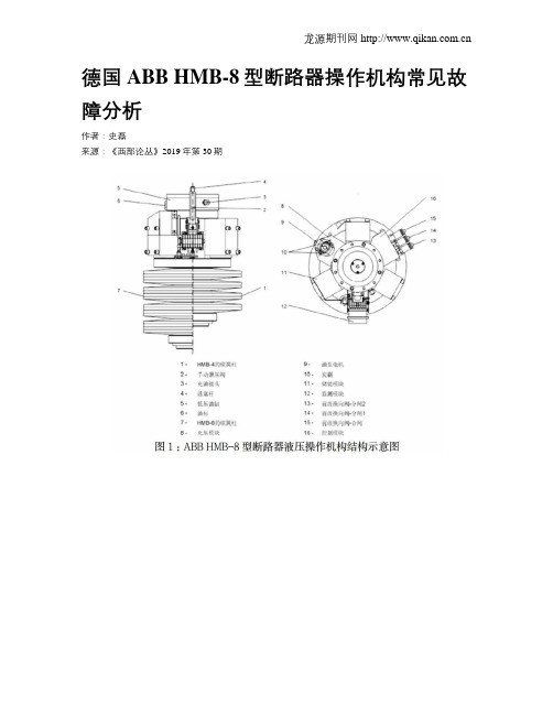
二、断路器液压操作机构结构示意图三、液压机构频繁打压故障1、液压油泵频繁打压的危害1.1储能模块、工作缸内活塞频繁压缩,使密封圈等密封件磨损显著增大,甚至或扫磨损,易造成机构内漏或使内漏不断加剧,故障扩大(机构压力低闭锁)。
1.2由于油中杂质引起的频繁打压,使运动部件之间的磨损加剧,划伤模块、工作缸内壁及活塞的机会增加。
1.3二次回路接触器接点烧损严重。
1.4电机启动频繁易烧损整流元件。
一般来说,对于HMB-8型液压操作机构,由于存在密封圈等薄弱密封环节,机构24h内启动1-3次可视为正常。
在断路器无操作或操作较少的情况下,油泵如果平均每天启动10次或每月启动超过300次,可以视为频繁打压故障(现场以报警或计数器为判据)。
HMB-8型液压操作机构频繁打压判据为24h内电机启动20次以上,此时需要对机构进行检查、处理。
2、引起液压油泵频繁打压原因2.1液压油外漏造成油压下降。
如模块连接处或密封面有滲油处、放油阀密封不严。
- 1、下载文档前请自行甄别文档内容的完整性,平台不提供额外的编辑、内容补充、找答案等附加服务。
- 2、"仅部分预览"的文档,不可在线预览部分如存在完整性等问题,可反馈申请退款(可完整预览的文档不适用该条件!)。
- 3、如文档侵犯您的权益,请联系客服反馈,我们会尽快为您处理(人工客服工作时间:9:00-18:30)。
• 储能不受温度影响
• 最新设计的密封系统
• 内置液压阻尼系统
• 噪音低 • 反作用力低,操作可靠性
达到最大 • 免维护,只需简单的检查
• 操作特性不变
• 现代制造技术
• 对所有液压功能的持续 自我监视
• 现代传感器技术并具有 监视功能
• 根据IEC进行完整的元件 试验和检查
• 断路器使用年限的增加
• 把断路器操作机构与新的 控制和维护概念相结合.
HMB型液压弹簧操作机构是根据1986 年设计定型的AHMA机构优化改进而成, 采用现代制造技术和模块化装配技术. 它结合了金属弹簧机械储能与液压力 传送和能量转换的优点.
• 气体绝缘开关设备 (GIS)
• 落地罐式断路器 (DTB) • 发电机出口断路器 (GCB)
活塞的差动面积来保持.
机构的任何操作都会释放碟簧柱的能量. 碟簧柱的这种释放由限位开关来感应 并启动液压泵.这样能对高压油缸进行 补充,当完全储能时,泵马达会停止.
液压功能: 机构释放,分闸位置
-6-
高压 低压
液压功能: 机构在合闸位置
设计
与AHMA-4/-8型机构的设计把所有液压 元件和功能结合在主圆筒上不同,HMB -4/-8型机构采用模块化设计,即五个 主要功能块通过螺丝结合到一个中心 件上去.这些功能块是:
-3-
优点
HMB-4型和HMB-8型液压弹簧 操作机构的主要优点是:
设计: 质量特点:
• 作为独立的操作机构具有 紧凑和模块化的设计
• 重量轻 • 能方便地装配到设备本体上 • 零部件数量少,使用经过充分
验证的部件和元件
• 小巧密封的油缸足够整个 运行年限的使用
磨损 • 极好的抗腐蚀性
采用独立模块的模块化设计, 具有如下的优点:
• 减少复杂性达到更好的 过程控制
• 预制模块的经济性好
• 生产周期/交货周期更短
• 在装配时可按客户规范 进行调整
• 维护方便 • 备件管理简化
-8-
储能模块
液压泵单元由泵马达,齿轮,偏心泵和一个放油旋塞 组成,凸装在输出圆筒的外部.低压油缸的两边均装 有油位计,便于观察.
带导向阀和切换阀的控制模块
储存模块由储存活塞和安装在工作圆筒上 的碟簧总成所组成
- 10 -
操作安全性
自1986年起ABB开始制造AHMA型 液压弹簧操作机构.第20,000台 机构于1998年交货.已安装断路 器上的操作机构总运行年限已超 过100,000年.把ABB操作机构的 故障统计数字与CIGRE的故障统 计数字相比,证明ABB制造的液压 弹簧操作机构具有极高的可靠性.
机构的安装法兰能精确地调节 以满足任何用途.所有的机构 均在工厂进行了元件试验,这样 就能把完整的机构交付给最终 用户来完成整台断路器.
使用标准的铝合金而不是AHMA型 机构中使用的铸铁,它有如下的 优点:
• 材料质量高 • 可用率高 • 工艺安全性高 • 经济的切割技术 • 设计灵活 • 硬化阳极处理以防
-7-
HMB-4/-8型操作机构的装置项目
元件 本体 扩展的本体 完整的操作机构
(HMB-4) (HMB-8)
储能模块 工作模块 储存模块 监视模块 控制模块 中间机座 辅助开关 整体外罩 防凝露加热器 低温加热器 选项 操作机构接线 现场电缆插入式连接器
• 合成式开关设备(ISS)
• 维护开支的减少以及对 免维护开关设备的需求
• 为提高可靠性,对操作机构 减少缺陷的需求.CIGRE (大电网会议)的故障统计 数字表明开关设备中的大 部分故障是由操作机构所 引起的.*
HMB机构家族能以同样的技术满足所有 SF6断路器(压气式和自吹式断路器) 的要求.基于客户需求的不断研发使得 ABB全球所有的SF6断路器都能配备了 ABB Calor Emag高压有限公司生产的 液压弹簧操作机构.ABB在瑞士,美国,意 大利和瑞典的公司在研发上的通力合作 极大地提高了开发成果.
当用于合闸的导向阀启动后,切换阀 由液压驱动到其合闸位置,这样就 把高压油引入输出活塞的底部.此时 此时在活塞两边的压力均为系统压力.
因为活塞底部的面积比活塞顶部的面
积要大,所以油压的差别推动活塞到
在压力释放阀合上且液压泵马达启 达断路器合闸位置.在合闸行程的末
动后,碟簧柱储能并且建立高压. 端,内部阻尼能终止移动且液压支持 此时,断路器处于分闸位置,由输出 力能把活塞保持在其动作结束位置.
在控制模块中,切换阀与油路连在一起 到达输出活塞,低压油缸和高压油缸. 切换阀活塞通过由螺线管启动的导向 阀来控制.控制模块还包括节流螺丝用 于调节分合闸速度以及高压试验接头.
储存模块
储能是通过由碟簧加载的三个 相同的储能圆筒实现.储存的 操作顺序是: 分-合分或合分- 合分.HMB-4型的弹簧柱由八个 单装弹簧组成,HMB-8型有16 片弹簧以两片一组安装来达到 更高的弹簧力.储能圆筒的三个 活塞直接作用于碟簧柱.这种 机械储能的优点是长期的稳定性, 可靠性并且不受温度变化的影响.
HMB-4
HMB-8
马达 直流电流操作 复合马达
- 额定电压 110/125 或 220/250
VDC
交流电流操作
带整流器(选项)
- 额定电压
• 储能模块 • 工作模块 • 储存模块 • 监视模块 • 控制模块
这种模块化设计扩大了其应用范围, 使得几个弹簧柱能适用于不同的储 能要求.同样,如果需要,可以方便 地调整输出活塞来改变机构使其适 用于其它类型的断路器.
液压功能: 机构在分闸位置
分闸操作
当用于分闸的导向阀启动后,切换阀 由液压驱动到其分闸位置,这样就把 输出活塞底部的高压油泵入低压油缸, 输出活塞到达断路器分闸位置并在 行程的末端受到阻尼,液压支持力能 把活塞保持在其动作结束位置.
高压
低压
输出活塞的功能是基于差动活塞 面积原则,在合闸和分闸位置提 供一个支持力.当需要大操作力 来开断大电流时,输出活塞的速度 会自然地降低而液压系统的效率 会提高,使得输出活塞的作用 力增大.
阻尼系统与活塞杆结合在一起建 立了阻尼压力,断路器的运动就 平缓地停止了.这样可以减少 加在断路器和基础上的机械负载. 操作机构的特性已通过实践得 以充分验证,其元件也同样,包括 导向阀,切换阀,输出活塞,泵的 块包括带旋转轴的弹簧 限位开关及其组件
监视模块由以下元件组成: 一个通 过旋转凸轮动作的限位开关,一个 固定在止推环上的齿轮座,一个 储能指示器和一个压力释放阀.弹 簧限位开关总成会一直监视储存 在弹簧柱中的能量.由于限位开关 与弹簧的移动直接耦合,可直接测 定能量多少并且测量结果不受温 度的影响.限位开关与分合闸 线圈的导向阀联锁来防止弹簧柱 中未储存所需能量时进行操作.断 路器操作后一个开关会启动泵马达 立刻再储能.即使弹簧由于高低压 部分间小的内部泄漏而用掉或损失 了很少的能量,泵也会启动,这种情 况在所有的液压系统都存在.组合式 的压力释放/压力限定阀位于弹簧 限位开关的上方.
• 在多种断路器上进行了 广泛的试验
• AHMA和HMB型机构已有超过 150,000年的使用经验
• 使用带孔螺丝调节分合闸速度
• 不受压力容器规程的限定
• 只需很少的调整或调节就很 容易与断路器配合
-4-
操作模式
液压泵把油从低压油缸打到三 个高压储能活塞处.停泵时,一个 逆止阀可防止高压油回流.储能 活塞环绕主圆筒布置来对碟形 弹簧柱进行储能.在操作范围内, 碟簧的弹簧力特性曲线十分平缓, 这个特性对断路器操作十分有利. 与单个弹簧相比,碟簧柱由若干 弹簧组成,即使某个弹簧故障也 不会影响断路器的操作,这样就 更具有优势.弹簧组的储能状态由 位置开关来持续监控.一个限位 开关能在需要时启动泵马达,储 能过低时闭锁操作,必要时发出告 警信号.可控的操作方式是:合分- 合分;分-合分;合分与分.通过弹 簧储能状态的位置监视和液压 泵的不时启动(之前不论有无分合 操作),操作功能的保证和监视 是在延长的待机阶段中实现的.
- 11 -
HMB-4/-8的技术参数
操作次序
储存的操作次序 分合分/合分-合分 可选的操作次序 分-合分-1分-合分 额定的操作次序 或合分-10秒-合分
简化的液压弹簧操作机构功能原理
1 差动圆筒 2 切换阀 3 储能 4 液压泵
-5-
压力建立 合闸操作
交货时的机构是处于无压的分闸 位置,能方便地与断路器装配在 一起.
在压力释放阀打开后,输出活塞能 通过手动来帮助装配并确保断 路器在装配后动作自如.
110/125 或 220/250
VAC
功能 储能监视 - 马达控制
- 闭锁 分 - 合分 - 闭锁 合分 - 闭锁 分
随着对SF6断路器使用年限要求的 提高,服务变得越来越重要.ABB能 为我们的客户提供以下的帮助:
• 一旦发生故障,最短的响应 时间
• 广泛的培训课程 • 对新式和老式设备的广泛
的产品知识 • 长期备品备件的供应 • 用新的操作机构来整修旧的
设备(改造)
HMB-4/-8型机构的设计是把已经 实践验证的AHMA-4/-8型组件和 功能以一种类似的方式结合到也 ABB断路器操作机构改造的一个 经过实践验证的但操作功较小的 例子是用HMB型操作机构来替换 HMB型机构中,包括HMB-1型,HMB- 旧的PKA型气动操作机构. 1S型,HMB-2型,HMB-2S型和HMB-3 型.在研发阶段,用系统分析法对 可能发生的故障形式进行了评估 (FMEA)并采用其结果来优化设计 使得机构尽可能地可靠.
除了采用成熟的设计和进行广泛 的试验,ABB现代化的制造技术和 质量保证措施一起用于生产该型 机构来确保一个可持续的和高质 量的生产成果.对机构元件实行 有记录的广泛试验验证和对机构 整体的出厂试验形成了一个很高 的制造标准.过程安全性通过统 计过程控制(SPC)来监视.高质量 的标准也来源于我们的供货商们, 它们参与了所有研发项目的前期 工作,是我们的长期合作伙伴.