LENZE_8400硬件接线
电脑组装各接口以及主机内部各种线的连接方法图解
电脑组装各接口以及主机内部各种线的连接方法图解有时候我们在组装一台电脑回家,总会遇到一些小问题需要我们自已来解决,然而主板上面的众多连接线我们如何来区分它,怎么认识主机箱内的所有硬件设备呢,及连接线呢?主机内各线的连接方法图解主机外连线主机外的连线虽然简单,但我们要一一弄清楚哪个接口插什么配件、作用是什么。
对于这些接口,最简单的连接方法就是对准针脚,向接口方向平直地插进去并固定好。
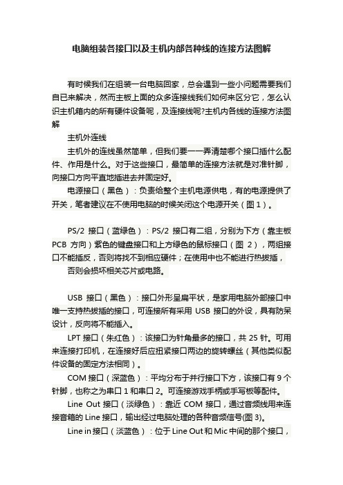
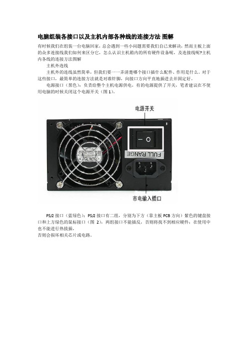
电源接口(黑色):负责给整个主机电源供电,有的电源提供了开关,笔者建议在不使用电脑的时候关闭这个电源开关(图1)。
PS/2接口(蓝绿色):PS/2接口有二组,分别为下方(靠主板PCB方向)紫色的键盘接口和上方绿色的鼠标接口(图2),两组接口不能插反,否则将找不到相应硬件;在使用中也不能进行热拔插,否则会损坏相关芯片或电路。
USB接口(黑色):接口外形呈扁平状,是家用电脑外部接口中唯一支持热拔插的接口,可连接所有采用USB接口的外设,具有防呆设计,反向将不能插入。
LPT接口(朱红色):该接口为针角最多的接口,共25针。
可用来连接打印机,在连接好后应扭紧接口两边的旋转螺丝(其他类似配件设备的固定方法相同)。
COM接口(深蓝色):平均分布于并行接口下方,该接口有9个针脚,也称之为串口1和串口2。
可连接游戏手柄或手写板等配件。
Line Out接口(淡绿色):靠近COM接口,通过音频线用来连接音箱的Line接口,输出经过电脑处理的各种音频信号(图3)。
Line in接口(淡蓝色):位于Line Out和Mic中间的那个接口,意为音频输入接口,需和其他音频专业设备相连,家庭用户一般闲置无用。
Mic接口(粉红色):粉红色是MM喜欢的颜色,而聊天也是MM喜欢的。
MIC接口可让二者兼得。
MIC接口与麦克风连接,用于聊天或者录音。
显卡接口(蓝色):蓝色的15针D-Sub接口是一种模拟信号输出接口(图4),用来双向传输视频信号到显示器。
该接口用来连接显示器上的15针视频线,需插稳并拧好两端的固定螺丝,以让插针与接口保持良好接触。
联想主板接线图

联想主板接线图F usb1 实例图示及对应接线图:F usb2 实例图示及对应接线图:F usb3 实例图示及对应接线图:联想主板13针前置音频实例图示及对应接线图:联想最新的主板和老一些的主板的音频接口都是联想自己的标准老款是7针的音频.新款是13针的音频相关图片: 老式的就不截图了下面看看现有普通机箱的音频线大概有几类普通散装7针接线整套的7针音频线普通散装7针接线标示不一样的图片那么我们怎么用普通机箱来完成联想音频的前置问题1先说普通7针的接法联想G31主板接口定义及准系统装置现市场上各种机箱的前置音频面板接线大概分为4种:标准7线接口、简化7线接口、5 线接口、4线接口。
对于5线、4线接口的面板,由于制造不符合标准,即使连接以后也不能组成正常的回路,后置无法正常发声的;对于这种面板的接法,由于无法实现前后置音频都能正常发声,这里就不说了。
看看现在市面上,一般机箱音频线的标示:BIOSTAR 两种前置音频接口和对应的接线方法:第一种、14针接口标准7线接法:1----MIC IN 2-----GND3----MIC POWER 4-----不接5----LINE OUT FR 6----- LINE OUT RR7----不接8-----空9----LINE OUT FL 10---- LINE OUT FR11---12闭合13-14闭合简化7线接法:1---Mic IN 2---GND3---MIC Bias 4----不接5---SPKOUT-R 6---SPKOUT-R7----不接8----空9----SPKOUT-L 10----SPKOUT-L11---12闭合13-14闭合第二种、10针接口前置音频接口位置如下图:注意:用户将连接器连接PC前置音频输出时,此时后置音频无输出!补充二:前置USB接口现在电脑的机箱大多数都有前置USB接口,在这个USB设备日渐丰富的年代,这极大地方便了我们。
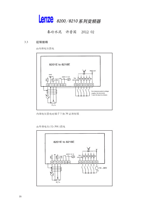
伦次变频器说明书

伦茨(Lenze)变频器8200Vector系列使用说明注:本说明适用于梳棉机FA231A所使用 Lenze E82EV系列变频器包括内容:1.标准接线及安装1.1 400V控制器的主电源接线1.2 电机接线1.3符合EMC标准的安装1.4控制端子接线及说明2. 用操作面板进行参数设定2.1访问,设定所有参数2.2拷贝参数到操作面板2.3从操作面板复制参数到变频器2.4 输出转速的在线调整--用操作面板输入频率(hz)与其他给定值相加3.重要参数代码说明3.1 C0014代码可设置控制模式3.2 电机数据的输入/自动检测(C0087;C0088;C0089;C0090;C0091;C0084;C0092;C0148)3.3 JOG固定频率给定值(C0037,C0038,C0039)3.4 给定值选择(C0001)3.5 模拟输入给定的调整(C0026;C0027)3.6 PTC电机温度监控(C0119)3.7 数字输入信号配置(C0007)3.8 最小输出频率(C0010)3.9 最大输出频率(C0011)3.10 主加速时间(C0012)3.11主减速时间(C0013)3.12快停减速时间(C0105)3.13数字输入信号E1-E6电平反相(C0114)3.14 模拟量输入范围设定(C0034)3.15电流极限设定(C0022,C0023)4.故障诊断及排除4.1运行状态显示4.2故障查询5. 梳棉机FA231A变频器参数设定表5.1 E82EV222S4B参数设定表5.2 E82EV751S4B参数设定表6.变频器调试程序表7.产品维护,保养要点1.标准接线及安装1.1 400V控制器的主电源接线1.2 电机接线见上图注:BR1,BR2外部制动电阻T1,T2电机温度监控PTC热敏电阻或热继电器1.3符合EMC标准的安装注:将控制线及电源线与电机电缆分开使用低寄生电容电缆。
每单位长度电容值:●芯/芯≤75pF/m●芯/屏蔽层≤150pF/mEMC电缆密封垫按铭牌进行电机接线使用表面导电的安装板以尽可能大的导电表面将电缆屏蔽层连到PE上。
电脑组装各接口以主机内部各种线的连接方法 图解
电脑组装各接口以及主机内部各种线的连接方法图解有时候我们在组装一台电脑回家,总会遇到一些小问题需要我们自已来解决,然而主板上面的众多连接线我们如何来区分它,怎么认识主机箱内的所有硬件设备呢,及连接线呢?主机内各线的连接方法图解主机外连线主机外的连线虽然简单,但我们要一一弄清楚哪个接口插什么配件、作用是什么。
对于这些接口,最简单的连接方法就是对准针脚,向接口方向平直地插进去并固定好。
电源接口(黑色):负责给整个主机电源供电,有的电源提供了开关,笔者建议在不使用电脑的时候关闭这个电源开关(图1)。
PS/2接口(蓝绿色):PS/2接口有二组,分别为下方(靠主板PCB方向)紫色的键盘接口和上方绿色的鼠标接口(图2),两组接口不能插反,否则将找不到相应硬件;在使用中也不能进行热拔插,否则会损坏相关芯片或电路。
USB接口(黑色):接口外形呈扁平状,是家用电脑外部接口中唯一支持热拔插的接口,可连接所有采用USB接口的外设,具有防呆设计,反向将不能插入。
LPT接口(朱红色):该接口为针角最多的接口,共25针。
可用来连接打印机,在连接好后应扭紧接口两边的旋转螺丝(其他类似配件设备的固定方法相同)。
COM接口(深蓝色):平均分布于并行接口下方,该接口有9个针脚,也称之为串口1和串口2。
可连接游戏手柄或手写板等配件。
Line Out接口(淡绿色):靠近COM接口,通过音频线用来连接音箱的Line接口,输出经过电脑处理的各种音频信号(图3)。
Line in接口(淡蓝色):位于Line Out和Mic中间的那个接口,意为音频输入接口,需和其他音频专业设备相连,家庭用户一般闲置无用。
Mic接口(粉红色):粉红色是MM喜欢的颜色,而聊天也是MM喜欢的。
MIC接口可让二者兼得。
MIC接口与麦克风连接,用于聊天或者录音。
显卡接口(蓝色):蓝色的15针D-Sub接口是一种模拟信号输出接口(图4),用来双向传输视频信号到显示器。
该接口用来连接显示器上的15针视频线,需插稳并拧好两端的固定螺丝,以让插针与接口保持良好接触。
Lenze培训-滚床8400protec
滚床驱动,8400 protec Highline
8400 protec Highline 可 Highline
8400 protec Highline 可插拔端子:
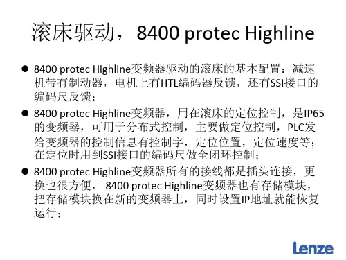
滚床驱动,8400 protec Highline
8400 protec Highline变频器驱动的滚床的应用程序是标准程 序,新调试一台滚床之需要调整参数即可,需要调整到的参 数如下: 1. 电机参数; 2. 机器参数; 3. 编码尺读数与电机编码器读数的标定; 4. 编码定位窗口的计算 5. 速度的标定; 6. 设定IP地址;
滚床驱动,8400 protec Highline
编码尺读数与电机编码器读数的标定 通过下拉菜单找到L_ComparePhi_2功能块,点击功能块上的按钮
滚床驱动,8400 protec Highline
编码尺读数与电机编码器读数的标定 弹出如下界面:
滚床驱动,8400 protec Highline
速度的标定 点功能块上的按钮进入参数设置界面如下:
滚床驱动,8400 protec Highline
速度的标定 1. C00490/2设定为16384; 2. C00492/2设定为4; 3. C00491/2设定为C00011的值;
滚床驱动,8400 protec Highline
速度的标定 在如下界面中点Basic Function
编码尺读数与电机编码器读数的标定 弹出如下界面:
滚床驱动,8400 protec Highline
编码尺读数与电机编码器读数的标定 计算Gain值:标定的功能是把编码尺的读数与电机编码器反 馈的数值对应起来,计算时要结合Feed Constant,减速比一 起计算,如本例中计算式为:
Lenze培训-剪式提升机8400topline
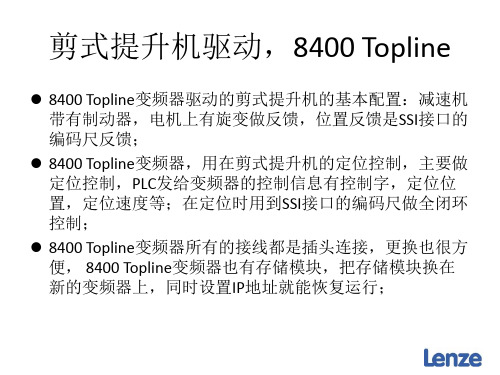
剪式提升机驱动,8400 Topline
速度的标定: 弹出如下界面:设定C00490/1=16384, C00491/1=1470=C0011,C00492/1=3;
剪式提升机驱动,8400 Topline
速度的标定: 设定定位曲线中参数,只使用一条定位曲线,如下操作: 点Basic Function按钮
防止SSI编码尺干扰或机械结构引起的剪式提升机抖动: 电机电缆控制器侧的接线要规范;
剪式提升机驱动,8400 Topline
防止SSI编码尺干扰或机械结构引起的剪式提升机抖动: 电机电缆控制器侧的接线要规范;
剪式提升机驱动,8400 Topline
防止SSI编码尺干扰或机械结构引起的剪式提升机抖动: 由于机械结构,升降机在升降过程中会出现恍动,引起读 码头读数也跟着变化而引起升降机抖动,可以采取如下措 施来确保升降机稳定运行;
剪式提升机驱动,8400 Topline
机器参数的设定 Mounting direction: Motor,参数C01206/1,电机安装方向, 用于改变电机的旋转方向; Reference Speed,参数号为C0011,电机参考速度,即电 机最大运行速度; 然后把反馈参数设置为SSI编码尺反馈,参数设置为 C00490=3;
剪式提升机驱动,8400 Topline
8400 Topline变频器驱动的剪式提升机的基本配置:减速机 带有制动器,电机上有旋变做反馈,位置反馈是SSI接口的 编码尺反馈; 8400 Topline变频器,用在剪式提升机的定位控制,主要做 定位控制,PLC发给变频器的控制信息有控制字,定位位 置,定位速度等;在定位时用到SSI接口的编码尺做全闭环 控制; 8400 Topline变频器所有的接线都是插头连接,更换也很方 便, 8400 Topline变频器也有存储模块,把存储模块换在 新的变频器上,同时设置IP地址就能恢复运行;
LENZE8200简明调试及典型接线
,(00 D11 D1/ D1&
f/02Lij8 # kl " f/0mn8 f/02Lio8 # kl " h g
,(10 )*#,
)*&+
r8& D11 $D1/$D1& /stp 100 u $ vwxyz{|P $ }~ 8 & E@FGH / %
!"
+)
+),)
,&’(),BCDEFGHIJ #KLMN,6OPQRSTUVWXYZ? $
! .-(( [\]^_‘ ! ! !
abc .-(( 0 .-,( 4$%defg]^ $ hijklm #.-(( n .-,( [\ ]^l’of Z?p’ qr_stu,6EF4$%./
vKL6wx # yz){|}~P $ }~P & e +1.(123 l 4$% $
!"
#$5(!
56 56
uM B vwxXyz{|}~v C MX{|} $ ]^
R "ST5UV0WXY #$0%D Z[ $ \]^ %_‘a[bcC ! V* #%$&E/%/
-./012 !3
,&, @A $4’&55 DE*+,
@ABCHI @A $4’&55 *+8=
,4, @ABC $ DE*+,
@ABCHI @A 67*89 *+8=
,3, @A 67*89 DE*+,
@A 67*89 HI @A 67*89 *+8=
*’’%! 8=
*+
,’, JK63 ,;, L$M,NOPQRS=T ,%, L$U,NOPVR8=T ,3, L$U,NOPQ ! VR
伦茨8400 motec变频器
Brochure | ENFrequency inverter 0.25 ... 132 kWLenze inverter – universally applicable.A multifunctional all-rounder applicable for all cases – just another way to perfectlydescribe the frequency inverter. Thanks to a high number of integrated functions,network interfaces and a simple parameter setting, the inverter is suitable for bothmechanical engineering and apparatus construction.Lenze inverters are an important component in modern drive solutions whichrange from the cloud via control systems to motors and geared motors.Typical application fields• Textile machines• Materials handling technology• Packaging technology• Forming technology• Consumer goods machines• Industrial air conditioning technology (pumps, fans & compressors)• Construction machines• Access control• etc.Features• The modular and scalable concept allows the selection of the inverter requiredfor the respective application.• The compact design allows an efficient installation for applications where spacemeans money.• Easy installation and OEM friendly as standard. Robust design for reducingcabling costs in large installations.• Interaction for each application level – from simple to complex!• Energy-efficient and high functionalityThe benefits for you• Lower investment costs• Less control cabinet space and costs• More productivity• More time for innovation• Sustainability• ReliabilityFeatures at a glance.A good usability of the devices ranging from installation to service reduces working time, costs and errors in handling. This makes installation with keyhole mounting and plug-in terminals particularly convenient.Programming your application is opti-mized for all application levels.The smartphone app via WLAN pro-vides only one of numerous interfaces to the device.User-friendlinessFlexibilityCompact designIn mechanical engineering andapparatus construction, space is limited and expensive. Thus, Lenze inverters are extremely compact to implement solutions and save costs.The i5.0 devices impress with a space-saving design with a width of 60 mm (up to 4.0 kW) and a depth of just 130 mm (up to 11 kW). Moreover, the devices can be be mounted directly next to each other without derating.Lenze offers one of the most com-prehensive solution portfolios formechanical engineering and apparatus construction.No matter which power, mains volt-ages, communication interfaces ordiagnostics options – our product range has the right solution optimized for the requirement.RobustnessIO-LinkCentralized/decentralizedMany machines and apparatus provide enough space for a compact inverter such as the i510 or i550.If your machine requires a lot of space, has a modular design or the space in the control cabinet is limited, we rec-ommend a decentralized installation close to the motor. This serves to avoid the installation costs of e.g. expensive motor cables.In many applications, a mixture of cen-tralized and decentralized drive tech-nology is advisable. Fortunately, the i5x0 cabinet and i5x0 protec inverters show the same drive behavior.For an intelligent integration ofsensors and actuators, IO-Link is used increasingly. If the system already con-tains an IO-Link master, inverters can be integrated cost-effectively. With the i550, Lenze is the first man-ufacturer to fulfil the IO-Link standard V1.1. This allows the inverter to be automatically parameterized for serial commissioning or in the event of service.Applications, for instance in the timber industry or intralogistics, place high demands on the components of the machines regarding robustness. Harsh environments are no problem for the i550 protec.Featuring the IP66 degree of protection (Indoor & Outdoor NEMA 4X), the tech-nology inside the housing is protected against dust and the device can be safely cleaned using water jets.i510 cabinet i550 cabineti550 protec8400 motec• Basic inverter IP20NEMA Open Type• 0.25 ... 11 kW• Standard inverter IP20• Universally applicable• 0.25 ... 110 kW• Standard inverter IP31 or IP66• Universally applicable• 0.37 ... 11 KW (expansion up to 75 kWplanned)• Standard inverter for motor orwall mounting IP65• Various connector options for power andsignals for minimum installation expenses• 0.37 ... 7.5 kW Configurablefor all requirements.Frequency inverterLenze offers a comprehensive inverter portfolio for mechanical engineering andapparatus construction. Whether control cabinet mounting, motor mounting ordecentralized mounting with terminals or with complete connection technology– our independent advice is geared towards finding the best solution for yourspecific case.The Lenze EASY Product Finder helps you configure your required frequencyinverter type in next to no time. In addition, you can retrieve all importanttechnical details such as data sheets, CAD data and EPLAN data.EASY Product Finderi510 and i550 cabineti510 and i550 cabinet form the inverter series for the control cabinet in a powerrange of 0.25 ... 132 kW. They are distinguished by the following attributes – slimdesign, scalable functionality and exceptionally user-friendly. The simple i510from 0.25 ... 11 kW and the universally applicable i550 from 0.25 ... 110 kW havethe same DNA but differ in functionality and are optimized for a good price/performance ratio.Highlights• Space saving design: 60 mm wide (up to 4 kW), 130 mm deep(up to 11 kW), with zero-clearance mounting• Innovative interaction options enable better set-up times than ever.• The wide-ranging modular system enables various product configurationsdepending on machine requirements• Optionally with "Safe Torque Off (STO)" with SIL 3 (ISO 13849-1 (EN 954-1) ) andPerformance Level e (EN 62061/EN 61800-5-2)• Flexibility: Get the i550 as a complete device or in individual components(Power Unit, Control Unit and Safety Unit)i510 cabineti550 cabinetPower range ·0.25 ... 110 kW Mounting ·Wall mounting ·InstallationDegree of protection ·IP20·NEMA Open Type ----Approvals·CE, UL, CSA, EAC, RoHS Connections ·1 AC 120 V ·1 AC 230 V ·1/3 AC 230 V ·3 AC 230 V·3 AC 400 V/480 V -·Standard I/O 5x digital input 1x digital output -·Application I/O:7x digital input 1x digital output PNP/NPN logic ·Standard I/O 2x analog input 1x analog output ·Application I/O: 2x analog input 2x analog output·Frequency input: 0 … 100 kHz·1x NO/NC relay (24 DC max. 2 A; 240 AC max. 3 A)·External 24 V supply and internal 24 V power supply unit -·Spring terminals, plug-in ·Evaluation of motor PTCOverload behavior·200 % for 3s; 150 % for 60s Motor controls·Servo control (SC-ASM) with feedback·Sensorless vector control for synchronous motors (up to 22 kW)·Sensorless vector control (SLVC)·Energy saving function (VFC-Eco)·V/f characteristic control linear/square-law (VFC plus)·V/f characteristic control with feedbackFunctions·DC-injection braking·Brake management for brake control with low rate of wear·Dynamic braking through brake resistor·S-ramps for smooth acceleration and deceleration ·Flying restart circuit, PID controller ·DC connection ·Safety engineering Safe Torque Off (STO)Networks·CANopen, Modbus RTU, Modbus TCP, IO-Link, EtherCAT,EtherNET/IP, PROFIBUS, PROFINET, POWERLINKAmbient temperature during operation·3K3 (-10 ... +55 °C) EN 60721-3-3 (derating of 2.5 %/°C above 45 °C)Power range ·0.25 ... 11 kW Mounting -·InstallationDegree of protection ·IP20·NEMA Open Type ----Approvals·CE, UL, CSA, EAC, RoHSConnections -·1 AC 230 V ·1/3 AC 230 V ·3 AC 230 V ·3 AC 400/480 V -·Basic I/O: 5x digital input 1x digital output -----·Basic I/O:2x analog input 1x analog output ---·no·1x NO/NC relay (24 DC max. 2 A; 240 AC max. 3 A)--·Spring terminals·Evaluation of motor PTCOverload behavior·200 % for 3 s; 150 % for 60 sMotor controls -·Sensorless vector control for synchronous motors (up to 22 kW)·Sensorless vector control (SLVC)·Energy saving function (VFC-Eco)·V/f characteristic control linear/square-law (VFC plus)-Functions·DC-injection braking·Brake management for brake control with low rate of wear -·S-ramps for smooth acceleration and deceleration ·Flying restart circuit, PID controller ·DC connection Safety engineering -Networks·CANopen, Modbus RTUAmbient temperature during operation·3K3 (-10 ... +55 °C) EN 60721-3-3 (derating of 2.5 %/°C above 45 °C)i550 proteci550 protec uses the same tried-and-tested technology used in i550 cabinet andonly differs in terms of a higher degree of housing protection with an adapteddesign. If your machine requires a lot of space, has a modular design or the spacein the control cabinet is limited, the universally applicable i550 protec (IP31and IP66 degree of protection) from 0.37 kW ... 11 kW (expansion up to 75 kWplanned) is the ideal solution for a decentralized installation close to the motor.Highlights• IP66 degree of protection (Indoor & Outdoor NEMA 4X) with protection againsthigh pressure water jets from any direction and dust tightness allows for use inharsh environment applications• USB Micro diagnostic interface on board• Optionally available with extension box with or without service switches• Optionally available with keypad or WLAN diagnostic module• Optionally available with "Safe Torque Off (STO)" with SIL 3 (ISO 13849-1(EN 954-1) ) and Performance Level e (EN 62061/EN 62061/EN 61800-5-2)i550 protecPower range·0.37 ... 11 kWMounting·Wall mounting·InstallationDegree of protection·IP31·NEMA 1·IP66·NEMA 4 x--Approvals·CE, UL, CSA, EAC, RoHSConnections·1 AC 120 V·1 AC 230 V·1/3 AC 230 V·3 AC 230 V·3 AC 400/480 V·3 AC 480 V/600 V·Standard I/O:5x digital input1x digital output----PNP/NPN logic·Standard I/O:2x analog input1x analog output---·Frequency input: 0 … 100 kHz·1x NO/NC relay (24 DC max. 2 A; 240 AC max. 3 A)·External 24 V supply andinternal 24 V power supply unit·Spring terminals·Evaluation of motor PTCOverload behavior·200 % for 3 s; 150 % for 60 sMotor controls·Servo control (SC-ASM) with feedback·Sensorless vector control for synchronous motors (up to 22 kW)·Sensorless vector control (SLVC)·Energy saving function (VFC-Eco)·V/f characteristic control linear/square-law (VFC plus)·V/f characteristic control with feedbackFunctions·DC-injection braking·Brake management for brake control with lowrate of wear·Dynamic braking through brake resistor·S-ramps for smooth acceleration and deceleration·Flying restart circuit, PID controller·DC connectionSafety engineering·Safe Torque Off (STO)Networks·CANopen, Modbus RTU, Modbus TCP, IO-Link, EtherCAT, EtherNET/IP, PROFINETAmbient temperature during operation·3K3 (-10 ... +55 °C) EN 60721-3-3 (derating of 2.5 %/°C above 45 °C)8400 motecThe 8400 motec is a frequency inverter for decentralized installation from0.37 ... 7.5 kW in IP65. In the three basic variants for motor mounting, wallmounting or wall mounting with service switch, it already offers a high degree offlexible solutions. Wherever the focus is on a safe and fast installation of drives, the8400 motec is the most beneficial solution, e.g. in spatially distributed applications.Motor mounting:In the case of motor mounting, the 8400 motec can be operated without deratingregardless of the alignment. Compact solution with Lenze MF motor (120 Hz).Wall mounting:Compact and flexible solution for wall mounting in IP65.Wall mounting with service switch:Wall-mounted device with 3 maintenance switches. Options for maximumflexibility in IP54.Highlights• Compact design• High degree of functionality, e.g. integrated brake rectifier• M12 signal connector for fieldbuses, IOs, external 24 V supply and STO• High variety of mains plugs for Harting Q4/2 (single or double),M15 or QUICKON QPD• Wall mounting without derating8400 motecPower range·0.25 ... 7.5 kWMounting·Wall mounting·Motor mountingDegree of protection·IP66·IP54 (with switching unit)----Approvals·CE, UL, CSA, EAC, RoHSConnections----·3 AC 400/480 V-·Standard I/O:5x digital input1x digital output1 inverter enable---PNP/NPN logic------·Frequency input: 0 … 10 kHz·1x NO/NC relay·External 24 V supplytogether with Ethernet-based fieldbuses and PROFIBUS-·Evaluation of motor PTCOverload behavior·200 % for 3 s; 150 % for 60 s·Motor controls-·Sensorless vector control for synchronous motors ·Sensorless vector control (SLVC)·Energy saving function (VFC-Eco)·V/f characteristic control linear/square-law (VFC plus)V/f characteristic control with feedbackFunctions·DC-injection braking·Brake management for brake control with low rate of wearwith integrated brake rectifier·Dynamic braking through brake resistor·S-ramps for smooth acceleration and deceleration·Flying restart circuit, PID controller-Safety engineeringSafe Torque Off (STO)Networks·CANopen, EtherCAT, EtherNET/IP, PROFIBUS, PROFINET,ASiAmbient temperature during operation·3K3 (-30 ... +55 °C) EN 60721-3-3 (derating of 2.5 %/°C above 45 °C)Technical data i510 cabinet inverterConnection to 230 V mainsi510 cabinet inverter Connection to 400 V mainsMains choke is generally prescribed for Light Duty with 15 kW.Connection to 120 V mains and 230 V mainsConnection to 400 V mainsMains choke is generally prescribed from 22 kW (for Light Duty from 15 kW).Connection to 120 V mains and 230 V mains with IP66 degree of protectionConnection to 400 V mains with IP66 degree of protection8400 motec inverter Connection to 400 V mainsDiagnostics and operation of the i5x0 cabinetFor diagnostics and parameterization, the keypad, the Lenze SMART Keypad app (iOS and Android) or the EASY Starter can be used.I5MADR0000000SI5MADK0000000S I5MADW0000000S I5MADU0000000S3 m cable 3 m cableI5MADR0000001S EWL0085/S5 m cable 5 m cableI5MADR0000002S EWL0086/S Functional safety for i5x0 cabinetThe safety function STO can also be ordered at a later date and retrofitted.I5MASAV000000S Product extensionsAccessoriesMains choke for i5x0 cabineti550 cabinet: generally prescribed from 22 kW (for Light Duty from 15 kW)i500 protec: integrated in the device if required (>= 30 kW)• Mains chokes reduce the effects of the inverter on the supplying mains by smoothing the harmonics.• The effective mains current is reduced which saves energy.• Mains chokes can be used without restrictions in conjunction with RFI filters.• Please note that the use of a mains choke reduces the mains voltage at the input of the inverter by 4 % (typical voltage drop across the mains choke).Filter Short Distance for i5x0 cabinetFilter type: RFI filter• C1 to 25 m • C2 to 50 m• Reduced leakage current, operation on 30-mA residual current circuit breaker possibleFilter Long Distance for i5x0 cabinetFilter type up to 15 kW: RFI filterFilter type from 22 kW: Mains filter (combination of RFI filter and mains choke)• C1 to 50 m • C2 to 100 m•Operation with 300 mA residual current circuit breakerBrake resistor for i550 cabinet• To decelerate greater moments of inertia or with a longer operation in generator mode, an external brake resistor is required.• The brake resistor absorbs the brake energy produced in generator mode and converts it into heat.Brake resistor for i550 protec• To decelerate greater moments of inertia or with a longer operation in generator mode, an external brake resistor is required.• The brake resistor absorbs the brake energy produced in generator mode and converts it into heat.Motor shield plate for i5x0 cabinetContents: Motor shield plate, fixing clip, terminal clamp.Exception: EZAMBHXM004 and EZAMBHXM005 only include terminal clamps as the shield plate comes supplied with the device Accessory sets for i5x0 protecThe bottom of the housing of the i510 protec and i550 protec inverters provides openings for connections to the mains, the motor and the control connections. To easily implement these connections in IP66, various connection sets are available.。