TRINAMIC驱动芯片选型手册2019版
英飞凌tricore用户手册 第24章 捕捉比较单元CCU6
移量 读写
CC62SR
捕获/比较映射 48H 寄存器通道
U, SV U, SV 0000 0000H
CC62
复位 类3
页码 24-38
捕获/比较控制寄存器
CMPSTAT 比较状态
60H
寄存器
CMPMODIF 比较状态调 64H 制寄存器
U, SV U, SV 0000 0000H 类3 U, SV U, SV 0000 0000H 类3
24.1 引言
CCU6单元由一个有三个捕获/比较通道的定时器T12块和一个有一个捕获比较通道 的定时器T13定时器块组成。T12通道可以独立产生PWM信号、接受捕获的触发信号或 他们联合产生控制信号模式来驱动AC电机或变频器。
一个状态位组可以通过映射寄存器同步更新参数值,并且灵活的产生中断请求信号 为高效的软件控制提供控制方法。
定时器13 块功能 • 有一个输出的独立比较通道 • 16位分辨率,最大计数频率=外设时钟 • 并发更新T13寄存器 • 可以同步到T12 • 在周期匹配和比较匹配产生中断 • 支持单触发模式 • 可用外部事件控制启动 • 有计数外部事件的能力
附加的特殊功能
• 为无刷DC驱动实现块整流 • 通过霍尔传感器模型进行位置检测 • 噪声过滤器支持的位置输入信号 • 为块整流提供的自动旋转速度测量和整流控制 • 综合集成性错误处理 • 通过外部信号(CTRAP)而不需要 CPU载入的快速急停 • 多通道AC驱动的控制模式 • 可选择输出电平并使其与上电步伐相适应
CC61SR
捕获/比较映射 44H 寄存器通道 CC61
U, SV U, SV 0000 0000H 类3
24-37 24-38 24-38
用户手册 CCU6, V0.3
TMC262步进电机驱动芯片

步进电机驱动芯片-TMC262
德国TRINAMIC推出史上功能最强步进电机驱动芯片-TMC262
TMC262可以精确、巧妙、随机动态地控制管理驱动芯片输入到电机的电流,即TMC262可以根据电机不同负载需求轻松自如地增加或减少其所输出电流,此功能在大大降低步进电机丢步概率的同时可以减少功率消耗该系列芯片也被称为绿色芯片,很好解决了由于功率过剩而产生的热量,从而可以较少电机和驱动器的发热量。
◆自带256高细分
◆支持step/dir控制信号输入;也支持20BitSPI接口控制
◆带有专利技术stallguard功能可以实现无需传感器精确测试电机负载
◆带有专利技术coolstep可以根据电机的负载自动调节驱动芯片输出的电流,避免因为超载而丢步,也减少电机的发热量,和其他驱动芯片相比节省75%的能量
◆内部自带256细分可以实现在低速时候平滑控制
◆最大驱动电流6A,驱动电压60V
◆高速驱动能力,可以驱动普通的2相步进电机达到5000RPM
◆集成过流,短路,过温等保护与诊断功能。
基于stm32和tmc5160的步进电机控制系统

关键词 :STM32F103VCT6 ;TMC5160 ;步进电机 ;DMX512 通信
中图分类号:TM383.6;TP273
文献标志码:A
DOI:10.3969/j.issn.1671-1041.2020.02.017 文章编号:1671-1041(2020)02-0063-04
Stepper Motor Control System Based on STM32 and TMC5160
Key words:STM32F103VCT6;TMC5160;stepper motor;DMX512 protocol
步 进 电 机 因 为 其 结 构 简 单、 控 制 方 式 容 易、 定 位 精 度高等优点,在各控制领域中广泛应用。随着生产自动化 要求的不断提高,步进电机的控制需求与日俱增,驱动方 式也已经非常成熟,在舞台灯光的控制系统中,对于步进 电机的远程控制也成为一种趋势。本文主要研究的是基于 STM32F103VCT6 单片机和 TMC5160 电机驱动芯片,应用 于舞台灯光等控制系统中,是可通过 DMX512 通信协议远 程控制的低成本,高可靠性的步进电机控制系统。
1 系统构成
本文中的步进电机控制系统的主控制芯片选用 STM32 系 列 的 STM32F103VCT6 单 片 机, 电 机 驱 动 芯 片 选 用 Trinamic 公司 2018 年新推出的 TMC5160。
STM32F103 系列单片机是意法半导体公司(ST)推出 的基于 ARM Cortex-M3 内核的 32 位处理器芯片,是一款 高性价比、速度快、效率高、外设功能丰富的单片机。
Zhang Jing1,Fan Yanyan1,Li Yong2 (1.China Nuclear Power Engineering Co.,Ltd.,Beijing,100840,China; 2.China Nuclear Control System Engineering Co.,Ltd.,Beijing,102401,China)
57步进电机的驱动电压及选型实例

市面上步进电机使用量,除了42步进电机之外就是57步进电机了,57步进电机在自动化设备行业的使用量甚至超过42步进电机。
那么57步进电机的驱动电压多少合适呢?我们来通过一些资料来对比分析一下就很清楚了。
通过这些资料也很容易明白57步进电机应该怎么样选型才合理。
57步进电机一般使用DC24V驱动电压,对于通常推荐的步进电机的工作转速90~900rpm范围内,24V驱动电压差不多够用,具体先看看不同机身长57步进电机的特性参数以及在DC24V驱动电压下的距频图。
从信浓57步进电机的59系列4线电机的参数表上可以看到,同样机身厚度的电机的保持力矩基本上没有多大差别。
再看看距频曲线图,这个距频图是同样机身厚度的不同参数的距频曲线集中展示在一张表格上,虽然保持力矩差不多,但额度电流越大的电机距频图越平坦,也就是随速度上升扭矩的衰减比较慢,所以这种电机适合跑高速,反之,额度电流低的电感比较大,适合跑低速,之所以说额度电流小电感大的步进电机适合跑低速,是因为低速运行的时候,电感大的电机一方面不容易发生共振,另一方面它的功耗小,发热量小。
我们看看三个机身长分别是48.5/54.5/77.5mm的电机在2000pps也就是600rpm时候的力矩最大值差不多是0.6/0.7/0.9Nm,机身长的电机的力矩还是明显大一些。
我们再看看这三个机身长分别是48.5/54.5/77.5mm的电机在4000pps 也就是1200rpm时候的力矩最大值差不多是0.42/0.45/0.42Nm,几乎没有什么区别,机身最长的电机的力矩甚至还小一些,为什么?这是因为机身越大的电机如果跑高速,对于驱动电压的要求就越高,如果驱动电压不够,高速情况下,机身长的电机的力矩可能还比不上机身短一些的步进电机,如果要高速扭矩大,就需要选机身比较长的电机并提高驱动电压,57步进电机的驱动电压可以提高到36V,48V等,具体多少合适要根据工作速度,负载大小,电源条件等综合评估、测试验证。
基于DSP和FPGA的多轴步进电机驱动控制板卡

电子技术• Electronic Technology96 •电子技术与软件工程 Electronic Technology & Software Engineering【关键词】步进电机 伺服控制 FPGA DSP1 技术现状在多轴步进电机伺服控制领域,目前其硬件构架主要有五类:(1)MCU/DSP + 单步进电机驱动器;(2)MCU/DSP+三轴/六轴步进电机驱动器+单步进电机驱动器;(3)FPGA+单步进电机驱动器;(4)PLC+单步进电机驱动器;(5)DSP 与FPGA+单步进电机驱动器对于第一类,虽然能够同时实现简单的多轴步进电机的伺服控制,但对于复杂的伺服控制系统,如系统中需要接入惯性测量、双北斗定位定向和上位机等各种串行信号和开关信号下,硬件系统外部接口不足;对于第二类,除了存在第一类的外部接口不足问题外,还因为需要一个三轴/六轴步进电机驱动器作为中转,整个控制系统的实时性无法得到保障;对于第三类,在同时满足系统对外的接口能力和系统的解算和存储能力的情况下,对FPGA 的要求较高,使得硬件系统成本升高。
另外目前FPGA 对电机控制领域的支持不如MCU 或DSP 完善,使得采用纯FPGA 作为核心处理器的硬件系统的软件编程较为复杂;对于第四类,由于环境适应性问题,一般无法满足在军工和航空航天上的应用;对于第五类,DSP 和FPGA 的控制板卡和单步进电机驱动器,对于多步进电机伺服控制系统,系统硬件较为分散,硬件体积大,成本较高。
2 硬件技术方案基于DSP 和FPGA 的多轴步进电机驱动控制板卡硬件主要包括四个部分:电源部分、DSP 与FPGA 部分、接口电路部分和步进电机驱动部分。
如图1所示。
2.1 电源部分系统外部输入直流电源的电压范围为19V 到59V ,通过TRACO 公司的THN 15WI 系列的DC/DC 转换模块将电压转换为5V 。
5V 电压到3.3V 、1.9V 、1.2采用TI 的可调电压转换模块PTH05000WAH 。
使用TMC5160控制器-驱动器IC让功能更强大
使用TMC5160控制器/驱动器IC让功能更强大
将TMC2100,TMC2130和TMC5130系列扩展应用到更大,更高电流的
步进电机。
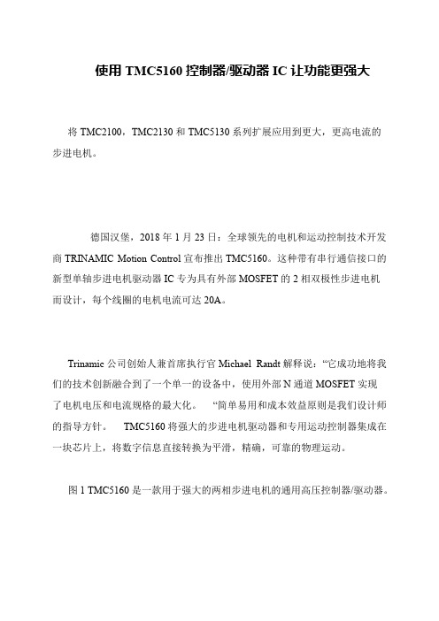
德国汉堡,2018年1月23日:全球领先的电机和运动控制技术开发商TRINAMIC Motion Control宣布推出TMC5160。
这种带有串行通信接口的新型单轴步进电机驱动器IC专为具有外部MOSFET的2相双极性步进电机
而设计,每个线圈的电机电流可达20A。
Trinamic公司创始人兼首席执行官Michael Randt解释说:“它成功地将我们的技术创新融合到了一个单一的设备中,使用外部N通道MOSFET实现
了电机电压和电流规格的最大化。
“简单易用和成本效益原则是我们设计师的指导方针。
TMC5160将强大的步进电机驱动器和专用运动控制器集成在一块芯片上,将数字信息直接转换为平滑,精确,可靠的物理运动。
图1 TMC5160是一款用于强大的两相步进电机的通用高压控制器/驱动器。
TMCM-1613 TMCM-1613-REC控制器 驱动器硬件手册说明书

TMCM-1613-CABLEMODULES FOR STEPPER MOTORS MODULESTRINAMIC Motion Control GmbH & Co. KGHamburg, GermanyHardware Version V 1.10HARDWARE MANUAL+ +TMCM-1613Single Axis BLDC Controller / Driver Block-commutation Hall-sensor basedAnalog+digital inputs / outputs Up-to 500W / 24V DCOpt. USB dongle for programming++++TMCM-1613-RECSingle Axis BLDC Controller / Driver Block-commutation Hall-sensor basedAnalog+digital inputs / outputs Up-to 500W / 24V DCActive rectifier add-on for DC-motor emulationOpt. USB dongle for programming++TMCM-1613 / TMCM-1613-REC Hardware Manual (V0.91 / 2016-MAR-29) 2 Table of contents1Life support policy (3)2Features (4)3Order codes (5)4Mechanical and Electrical Interfacing (6)4.1Dimensions and Mounting Holes (6)4.2Board mounting considerations (6)5Connectors of TMCM-1613 / TMCM-1613-REC (7)5.1TMCM-1613 Power supply connection (8)5.2TMCM-1613-REC Power supply connection (9)5.3BLDC motor connection (10)5.4VIN+ DETECT (TMCM-1613 only) (10)5.5Hall sensor connector (TMCM-1613 and TMCM-1613-REC) (10)5.6I/O connector (TMCM-1613 and TMCM-1613-REC) (10)6On-board LEDs (12)7Operational ratings (13)8Functional Description (14)9Revision History (15)9.1Document revision (15)9.2Hardware revision (15)10References (16)TMCM-1613 / TMCM-1613-REC Hardware Manual (V0.91 / 2016-MAR-29) 3 1Life support policyTRINAMIC Motion Control GmbH & Co. KG does not authorizeor warrant any of its products for use in life support systems,without the specific written consent of TRINAMIC MotionControl GmbH & Co. KG.Life support systems are equipment intended to support orsustain life, and whose failure to perform, when properly usedin accordance with instructions provided, can be reasonablyexpected to result in personal injury or death.© TRINAMIC Motion Control GmbH & Co. KG 2015, 2016Information given in this data sheet is believed to be accurateand reliable. However neither responsibility is assumed for theconsequences of its use nor for any infringement of patents orother rights of third parties, which may result from its use.Specifications are subject to change without notice.TMCM-1613 / TMCM-1613-REC Hardware Manual (V0.91 / 2016-MAR-29) 4 2FeaturesThe TMCM-1613 is a single axis controller/driver module for 2-phase brushless DC motors (BLDC). It supports hall-sensor based block-commutation for supply voltages of up-to nom. 24V DC and electrical power of up-to 500W. It offers one analog input and two optically isolated digital inputs for easy application integration. Key parameters and different operation modes can be configured using an optional isolated USB communication interface dongle. Together with an optional rectifier add-on board DC motor emulation is possible with supply voltage level defining motor speed and polarity defining motor direction.M AIN C HARACTERISTICSMotor type∙Block commutated 3 phase BLDC motors with hall sensors∙Motor power up-to 500W∙7V … 24V nominal supply voltageHighlights∙High-efficiency operation, low power-dissipation∙Lower supply voltage limit: 7V∙DC motor emulation with optional add-on rectifier board (part of TMCM-1613-REC)∙Open-frame enclosure∙Supports the TRINAMIC TMCL protocol and the TMCL software environment for parameterizing (with optional TMCM-1613-USB dongle)Interfaces∙2x digital inputs, 24V, optically-isolated (can be configured as high-side or low-side switch inputs)∙1x analog input (0..10V)∙1x digital (open-drain) output (pin-sharing with analog input)∙Optional communication interface via digital input and outputSoftware∙Via TMCM-1613-USB-Dongle: TMCL™ remote (direct mode). Fully supported by TMCL-IDE (PC based integrated development environment) incl. firmware updatesMechanical data∙Board size: 160mm x 100mm, overall height 27mm max. (without mating connectors and cables)∙6x M3 mounting holesPlease see separate TMCM-1613 Software / Firmware documentation for additional information regarding operation modes and programming using the optional TMCM-1613-USB dongle.TMCM-1613 / TMCM-1613-REC Hardware Manual (V0.91 / 2016-MAR-29) 5 3Order codesThe TMCM-1613 BLDC unit and its optional components are available as:Table 3.1: TMCM-1613 order codeA cable loom set is available for this module, also:Table 3.2: TMCM-1613 Cable loom order codeTMCM-1613 / TMCM-1613-REC Hardware Manual (V0.91 / 2016-MAR-29) 6 4Mechanical and Electrical Interfacing4.1Dimensions and Mounting HolesThe dimensions of the controller/driver unit are approx. 76mm x 70mm x 25mm. There are four mounting holes for M4 screws (4.2mm diameter).Figure 4.1 Dimensions of TMCM-1613 and position of mounting holes4.2Board mounting considerationsThe TMCM-1613 unit offers four mounting holes for M4 screws (4.2mm diameter). The length of the screws should be at least 8.6mm. The unit should be mounted to a flat surface. Any heat conducting material – e.g. a metal plate is preferred.While all four mounting holes are electrically isolated supply ground of the TMCM-1613 is connected to the U-profile frame via a combination of 1M || 10nF (500V) resistor + capacitor parallel combination.TMCM-1613 / TMCM-1613-REC Hardware Manual (V0.91 / 2016-MAR-29) 75 Connectors of TMCM-1613 / TMCM-1613-RECUV W+24V GNDVIN+ DETECTDIN_COM5DIN1DIN034AIN / DOUT0GND12(used in conjunction with the optional rectifier add-on board)I/OsHALL35HALL2HALL134+5V OUT GND 12Hall sensorFigure 5.1: TMCM-1613 connectorsDIN_COM5DIN1DIN034AIN / DOUT0GND12I/OsHALL35HALL2HALL134+5V OUT GND 12Hall sensorVIN+UV WBottom PCBVIN-Figure 5.2: TMCM-1613-REC connectorsTMCM-1613 / TMCM-1613-REC Hardware Manual (V0.91 / 2016-MAR-29) 8Table 5.1 Connectors and mating connectors5.1 TMCM-1613 Power supply connectionThe TMCM-1613 module offers two M4 contacts for power supply input connection.+24V GNDFigure 5.3: TMCM-1613 Power supply inputTMCM-1613 / TMCM-1613-REC Hardware Manual (V0.91 / 2016-MAR-29)95.2TMCM-1613-REC Power supply connectionThe TMCM-1613-REC module offers two M4 contacts for power supply connection.VIN+VIN-Figure 5.4: TMCM-1613-REC Power supply inputVIN+ is the nominal positive supply input – VIN- the nominal negative supply input. Nevertheless, any reverse polarity will be detected by the unit and internally corrected (reversed). Please note: the integrated active rectifier has been designed in order to support motor control based on supply voltage level (motor speed) and supply voltage polarity (motor direction) as commonly known from DC-motor control. It is not suitable for rectifying AC supply (e.g. 50/60Hz).5.3BLDC motor connectionThe module offers three M4 screw contacts for BLDC motor connection.U V WFigure 5.5: BLDC motor coil connectionIn addition to the motor coils please make sure to connect motor hall sensor signals, also (see hall sensor connector).5.4VIN+ DETECT (TMCM-1613 only)This M4 screw contact is used by the optional rectifier add-on board (part of the TMCM-1613-REC) in order to detect the supply voltage polarity of the TMCM-1613-REC supply voltage input.5.5Hall sensor connector (TMCM-1613 and TMCM-1613-REC)The module offers a 5pin JST PH series connector for motor hall sensor signal connection.15Table 5.1: Hall sensor connector5.6I/O connector (TMCM-1613 and TMCM-1613-REC)The module offers a 5pin JST PH series connector for one analog input (0..10V), one digital output (open-drain, max. 100mA, 30V) and two digital inputs (for +24V signals). The two digital inputs are optically isolated. This way they can be used with the DC motor emulation mode with the optional rectifier add-on board without additional external protection circuit.15Table 5.2: Hall sensor connectorThe digital inputs support the connection of high-side (typically referred to as pnp) and low-side (typically referred to as npn) switches. The common supply input for the digital inputs has to be connected either to GND or to supply voltage of the input signals.microcontrollermicrocontrollerFigure 5.6 Using NPN switches (connection to GND) for the digital inputsmicrocontrollermicrocontrollerFigure 5.7 Using PNP switches (connection to input signal supply / +24V) for the digital inputs6On-board LEDsThe TMCM-1613 board offers one green LEDs. This is located close to the two 5pin JST PH series connectors. The function of the LED is firmware dependent. With current firmware version the LED will be flashing slowly during standard firmware execution.Green LEDFigure 6.1: On-board green LED7Operational ratingsThe operational ratings show the intended or the characteristic ranges and should be used as design values.In no case shall the maximum values be exceeded.*) absolute max. (even for short time). Supply voltage spikes especially with higher load should be taken into account here. At higher supply voltages it is strongly recommended to add external buffer / filter capacitors to the supply input.PERATIONAL ATINGS OF ALL IGNAL NPUTSTable 7.2 Operational ratings of hall sensor signal inputsPERATIONAL ATINGS OF NPUTS AND UTPUTTable 7.3 Operational ratings of inputs and outputs8Functional DescriptionThe TMCM-1613 / TMCM-1613-REC modules are highly integrated powerful (up-to 500W) BLDC controller / driver units for typical supply voltages of +12V and +24V. The units offer easy setup of BLDC motor control applications supporting hall sensor based block-commutation of the attached BLDC motor. Two digital inputs and one analog input are available together with a number of pre-defined stand-alone operating modes (please see separate firmware manual for more details). An optional USB converter dongle supports full remote control of all main parameters with the option to store settings permanently on the units. An optional active input supply rectifier (part of the TMCM-1613-REC) allows DC-motor like control of a BLDC motor (supply voltage level defined velocity and supply voltage polarity defined direction of rotation)In Figure 8.1 / 8.2 the main parts of the TMCM-1613 / TMCM-1613-REC are shown:-Microcontroller, responsible for overall control and 3-phase pwm generation-Pre-driver with integrated analog amplifier for the single-shunt motor current measurement (based on TMC6130)-MOSFET driver bridge-Part of the TMCM-1613-REC, only: active rectifier at supply input+24V DCDigital InputsAnalog Input /Digital OutputFigure 8.1: Main parts of the TMCM-1613+24V DCDigital InputsAnalog Input /Digital OutputFigure 8.2: Main parts of the TMCM-1613-REC9Revision History9.1 Document revisionTable 9.1: Document revision9.2 Hardware revisionTable 9.2: Hardware revision TMCM-1613Table 9.3: Hardware revision TMCM-1613-REC rectifier add-on boardTable 9.4: Hardware revision of TMCM-1613-USB communication dongle10References[JST] JST connector/[TMC6130] TMC6130 datasheetManual available on . [TMCL-IDE] TMCL-IDE User ManualManual available on .TMCM-1613-CABLE。
TRINAMIC 产品指南说明书

TRINAMICTRINAMIC – SMART SOLUTIONS FORMOTION CONTROLTRINAMIC is a fabless semiconductor company and serves the market withself developed integrated circuits for the control of small electrical motors ina wide variety of applications. TRINAMIC’s integrated circuits are manufacturedto the highest standards in the world’s most advanced manufacturing plants.2TRINAMIC PRODUCT GUIDE3TRINAMIC PRODUCT GUIDEWhile the competition often comes from semicon-ductor technology and focuses on it, TRINAMIC is at home in both worlds – the world of motors and the world of IC design.The products – whether they are IC s, modules or the mechatronic systems (PAN drive TM ) – are in use all over the world and are selected because of their superior price/performance ratio.Applications are everywhere, where small motors are deployed and the growth of such small drives is increasing rapidly. In growing markets like biotech, medical, lab automation, semiconductor handling, TRINAMIC IC s control complex devices with dozens of axis.Traditional industries that are undergoing a para- digm change and are replacing complex mechanics by decentralized solutions that are synchronized via bus systems, count on TRINAMIC : Examples are the textile machines and furniture manufac-turing equipment.Close to the market, TRINAMIC continuously develops new products with innovative features, driven by the customers need for a higher degree of miniaturization, higher efficiency, diagnostics, and protection to enable the reliability of the complete system.TRINAMIC customers benefit from our encompass-ing knowledge about motor physics and from the extensive library of application knowledge which the company has built over the years. For custom-ers, TRINAMIC s application driven approach means that they do not need an indepth knowledgeabout motors, DSPs, or control circuitry in general. Consequently, the design phase saves the labor and costs.TRINAMIC also offers complete modules, includinghardware and software for specific motor control requirements. The modules combine TRINAMIC ’s dedicated stepper control and driver IC s with extensive experience in designing custom and off-the-shelf motion control solutions.TRINAMIC makes the difference!TRINAMICsensOstep TM sensOstep TM is based on a magnetic angularposition encoder system with low to mediumresolution for PAN drive TM mechatronic solutions. Itconsists of a small magnet positioned at the backend of a stepper motor axis and a Hall-sensor ICwith integrated digital signal processing (e.g. forautomatic gain control, temperature compensationetc.) placed above the magnet on the back side of a motor mounted printed circuit board. Startingat resolutions of 8 bit (256 steps) per revolution – which is completely sufficient for detecting step losses with standard 1.8° stepper motors – it is currently available with up-to 12bit (4096 steps). This increased resolution is sufficient for regaining position after step-loss for many applications with-out requiring any additional reference procedure.stallGuard TM TRINAMIC’s patented sensorless stall detectionstallGuard TM enables customers to detect mechani-cal overload conditions and stall conditions with-out external sensors, by measuring the load at apredefined point where a step loss has not yetoccurred. Thus, eliminates the need for reference or end switches. This reduces cost and complex-ity of applications, where a reference point is required. When compared to pure mechanical referencing, stress on the mechanic and noise is reduced.chopSync TM The patented chopSync TM feature allows veryhigh velocity operation of stepper motors usingthe standard TRINAMIC [stepper motor] driversTMC236, TMC239, TMC246 and TMC249. This isachieved by reducing resonances occurring when operating the motor at velocities where the EMF voltage exceeds the level of the supply voltage. With chopSync TM, motor velocities of several 1000 RPM can be reached.TMCL TM TMCL TM – the TRINAMIC Motion Control Language – is a programming language dedicated to motioncontrol applications. The software includes com-mands for moving one or more motor axes atcertain velocities or to certain positions and forsetting all relevant parameters of the motion con-troller. It is possible to access additional general purpose digital and analog inputs and outputs. TMCL TM is available on most TRINAM IC modules with integrated motion controller. Program de-velopment is supported by the TMCL-IDE – a PC based integrated development environment which is available free of charge.stallGuard2TM Improved version of the successfull stallGuard™feature. stallGuard2™ is the world’s first sensor-less high resolution load detection implementedin a standard stepper motor driver. This gives theuser easy and cost effective real time feedback of his application. It enables to scan the motion system without additional sensors. This can help to find the right motor and mechanics during development phase or to detect abrasion or mechanical stiffnesscoolStep TM Sensorless load dependent current control usingthe stallGuard2™ feature. First time coolStep™enables to drive a stepper motor in a energy ef-ficient way. Up to now stepper motors are drivenwith constant current. The new TMC260, TMC261and TMC262 stepper motor driver series detects the actual load of the motor and adjusts the current accordingly. This eliminates the security current margin and allow also to boost the motor avoiding stall and step loss to improve the reli-ability of the entire system.spreadCycle New patent pending constant Toff chopperscheme. Using the spreadCycle chopper the µStepcurrent sine wave is always well formed witha smooth zero crossing. Due to this effect the stepper motor can be driven very fast without resonance effects. All the coolStep™ drivers are using this new technology.hallFX TM hall FX TM generates back EMF based hallsensor like signals for the sensorless commutation of BLDC(also two phase motor when using 2 TMC603 asgate driver) motors. hall FX TM can be easily integrat-ed into your drive, since it directly emulates hall sensors and does not require complex software components to be added to your controller.5TRINAMIC PRODUCT GUIDE6TRINAMIC PRODUCT GUIDELONG LIFE AVAILABILIT YTRINAMIC offers lifecycles of up to 10years for almost all of our products, which reduces costs of re-designing, re-qualification and re-certifying for our customers. This does not only save valuable resources but reduces time-to-market.QUALIT YToday TRINAMIC has strategic allianceswith partners to ensure access to the latest technologies and processes.TRINAMIC is ISO 9001:2000 certified by Ger-manischer Lloyd and EN ISO 13485 certified for “Medical Components” by Medcert.The EtherCAT Technology Group is a global organization in which OEM, End Users and Technology Providers join in order to support and promote the tech-nology development. EtherCAT sets new standards for real-time performance and topology flexibility, whilst meeting or undercutting field bus cost levels.Our engineering team and customer service offers: f High-level specification, -jointly with customer f Technical specification and system architecture f IC s and PCB in-house design f Software development f Fast prototypingf Testing and qualification f Logistic warehousef After sales & technical supportf Online support forum: /ttdg f RMA repairTRINAMIC MEMBERSHIPSTRINAMICs ambitions are to commence different innovation platforms, where various industries and leading suppliers join forces to support, promote and advance the technology.TRINAMIC is member of the following organizations:RESPONSIBILITY –PROVIDED BY TRINAMIC7TRINAMIC PRODUCT GUIDECiA is the international users’ andmanufacturers’ group that develops and supports CANopen and other CAN-based higher-layer protocols. The nonprofit group was founded in 1992 to provide CAN-based technical, product and market-ing information.www.can-cia.de INNOMAG is an innovate platform for Magnetic Microsystems that combines the interests and potentials of manufacturers, service providers and users in a network. The target is to develop applications of magnetic Microsystems and nanotech-nologies in Germany. TRINAMIC GREENWe refer to the Directive 2002/95/EC of the European Parliament and the Council on the Restriction of the use of certain Hazardous Substances in electrical and electronic equipment. That means, all electrical and electronic equipment put on the market by TRINAMIC does not contain lead, mercury,cadmium, hexavalent chromium, polybromiated biphenyls (PBB ) or polybromiated diphenyl ethers (PBDE ) in terms of the RoHS Directive.COOPERATION8TRINAMIC PRODUCT GUIDE* also two phase motor when using 2 TMC60x as gate driverMOTION & INTERFACE CONTROLLERBLDC DRIVER WITH BACK-EMF SUPPORT, PROTECTION AND CURRENT MEASUREMENTINTEGRATED MOTION CONTROLLER AND DRIVER FOR STEPPER MOTORS9TRINAMIC PRODUCT GUIDEPOWER DRIVER FOR STEPPER MOTORSS/D Step/Direction10TRINAMIC PRODUCT GUIDEBL DC MOTOR CONTROLLER/DRIVERPIEZO MOTOR DRIVER11TRINAMIC PRODUCT GUIDESTEPPER MOTOR DRIVERS/D Step/Direction12TRINAMIC PRODUCT GUIDETMCM-1060TMCM-1180STEPPER MOTOR DRIVER + CONTROLLER WITH COOLSTEP™13TRINAMIC PRODUCT GUIDE14TRINAMICPRODUCT GUIDE STEPPER MOTOR CONTROLLER/DRIVERS/D Step/Direction15TRINAMICPRODUCT GUIDE*1) optional with additional TMCM-323*2) General Purpose16TRINAMIC PRODUCT GUIDEPANdrives TM WITH STEPPER MOTORS/D Step/Direction17TRINAMICPRODUCT GUIDEPANdrives TM WITH BLDC MOTORBIPOLAR HYBRID STEPPER MOTORSDisclaimerTRINAMIC reserves the right to make changes in the device or specifications described herein without notice. Information in this document is subject to change without notice.Please refer to the corresponding data sheets available on or on CD for detailed information. Any copying, disclosing or otherwise making use of the information is strictly prohibited.Life Support PolicyTRINAMIC Motion Control GmbH & Co. KG does not authorize or warrant any of its products for use in life support systems, without the specific written consent of TRINAMIC Motion Control GmbH & Co. KG.Copyright 2011Printed in Germany18TRINAMIC PRODUCT GUIDE19TRINAMIC PRODUCT GUIDEBRUSHLESS DC MOTOR WITH INTEGRATED HALL SENSORSVERSION 2.0 2011TRINAMIC Motion Control GmbH & Co. KGWaterloohain 5 • 22769 Hamburg • Germany。
- 1、下载文档前请自行甄别文档内容的完整性,平台不提供额外的编辑、内容补充、找答案等附加服务。
- 2、"仅部分预览"的文档,不可在线预览部分如存在完整性等问题,可反馈申请退款(可完整预览的文档不适用该条件!)。
- 3、如文档侵犯您的权益,请联系客服反馈,我们会尽快为您处理(人工客服工作时间:9:00-18:30)。
选型手册 2019集成电路我们将数字信号转化为物理运动关于我们拥有数以十年构筑高可靠性嵌入式构架的行业经验Trinamic 是一家在嵌入式电机运动控制领域的全球领导企业。
我们的芯片和微控制系统将数字信号和现实物理世界联系在一起。
我们的工程师是解决现实世界问题的专家, 他们几十年的经验体现在我们的每一个产品中。
Trinamic代表了精密、可靠和高效。
2 Trinamic 选型手册电动机是日常生活中必不可少的一部分,近年来,这些设备的使用量持续上升。
中产阶级的不断壮大,加上家庭自动化程度的提高,以及家庭周围电动马达驱动的产品数量的增加,是经济增长的主要动力”使用TRINAMIC技术来提升您的产品品质人类生活环境对自动化不断增加的需求趋势导致了控制运动系统的爆炸式增长。
产品开发人员必须处理日益复杂的系统,而且很难成为所有领域的专家。
Trinamic通过一种基于API的方法解决了这一问题,帮住用户缩短其产品上市时间,节约了成本,并最终提高产品性能。
Trinamic产品服务于多个市场,包括实验室自动化,工厂自动化,半导体设备,纺织设备,机器人,金融设备......等对可靠性要求比较高的场合。
Bryan Turnbough, IHS分析师。
我们最新的产品为高速增长的新兴市场,如3D打印,医疗泵和自动化移液提升了新的性能标准。
为什么世界上最具前瞻性的公司一再选择Trinamic?诚然, 有些人选择我们是因为我们的产品性能优越。
然而,我们的大多数客户选择我们,是因为我们对运动控制的专注 为用户提供了深入的应用知识,并使我们的客户能够在他们的特定领域更快地创新。
Trinamic 选型手册 3Trinamic带来的创新TRINAMIC是一家具有20多年运动控制芯片、模块和机电驱动设计和营销经验的创新型公司。
在其历史上,TRINAMIC工程师获得了许多专利,包括无传感器电机负载检测和自动混合衰减步进电机无传感器力矩测量。
StallGuard™提供具有成本效益的实时反馈的负载角,这是世界上第一个在标准步进电机驱动程序中实现的无传感器负载检测的技术。
StallGuard™StallGuard™ 不需要原点和限位传感器。
这降低了需要精确寻找参考点的应用成本和复杂性。
高分辨率的 StallGuard2™反馈技术可以允许持续检测系统状况。
依靠StallGuard2™ 的负载值,CoolStep™ 技术可以实现无传感器电流随负载动态变化。
驱动器总是以最佳的输出电流来驱动电机,因此能够达到节能效果。
CoolStep™不需要任何传感器, CoolStep™ 消除了对安全余量电流的需求, 提升电机性能, 避免了堵转和丢步,提高了整个系统的可靠性。
集成方案通过将运动控制功能和驱动功能集成在单一的器件中。
它结合了一个灵活的硬件斜坡发生器用于自动目标位置控制与行业最先进的步进电机驱动功能。
cDriver™高集成度,高能源效率,和小尺寸,为小型化和可扩展系统提供经济型灵活的解决方案完整的解决方案将经验学习降到最低,同时提供了最佳的性能。
4 Trinamic 选型手册StealthChop™ 实现对步进电机异常安静的驱动.低速运转的电机会出现磁致现象,这种现象会产生可听见的高频噪音。
StealthChop™基于电流反馈,芯片采用基于电压调制方式调节电流,使电流波动最小化。
StealthChop™的应用可以使电机噪音低于10 db,大大低于传统的电流调制方式。
SixPoint™六点斜坡曲线控制允许更加快速的完成定位,通过在线性轨迹曲线上加入可以自由配置的启动/停止频率以及在高速时候添加一个额外的减加速度。
SixPoint™六点斜坡曲线控制和传统的梯形加减速相比减少了加速阶段产生的抖动。
在一些要求高速定位控制场合以及处理一些对晃动敏感的物品或者物体的惯量比较大时,S型正弦曲线轨迹是必须的。
使用 SpreadCycle™,呈现正弦波的微步电流可以一直保持完美的波形,在电流零点处能平滑过零点,没有电流死区。
采用 SpreadCycle™的驱动能消除由于电机反电动势带来的电流波形跳动。
SpreadCycle™步进电机可以实现高速运动,而且运行平稳,不会产生振动。
减少了共振,提高了效率,因为没有能量被用在共振上面。
Trinamic Motion Control Language 是一套致力于运动控制的可编程语言。
它采用了简单易懂的指令完成定位控制以及设置运动控制的所有参数, 加速用户产品开发。
TMCL™通过开放的协议,用户可以使用任何一种高级来控制电机。
它支持TMCL-IDE一个基于PC的集成开发环境。
Trinamic选型手册 5数字科技正对制造业产生巨大影响,诸如3D打印,CNC机床和激光切割设备变的更加成熟和被人们所接受。
现实中的物品可以直接通过软件的设计而被加工出来。
微型电机变得无处不在快速增材加工和数字制造都需要精确可靠的运动控制。
Trinamic拥有丰富的3D打印制造经验,为未来的制造加工提供解决方案。
6 Trinamic 选型手册只要需要可靠定位的应用,Trinamic都可以提供可靠的基于硬件的系统解决方案。
您的应用是什么?Trinamic的微控制系统适合所有需要运动控制的应用。
我们的产品为数字制造、医疗设备和实验室自动化等应用设定了性能标准Trinamic选型手册 7通过学习Landungsbrücke开发板套装来开始 您的设计,可以从支持有多种类型的电机和开发板中选择。
MCU主板无论您的应用是什么都可以采用Landungsbrücke来开始您的设计。
在您的应用中测试和比较不同的驱动选项。
Landungsbrücke使设计出新产品比以往任何时候都更加容易。
芯片开发板套装芯片开发板8 Trinamic 选型手册开源硬件与开源软件的原理和方法基本相同,我们相信用户可以通过学习我们的设计,去理解它们是如何工作,并对其进行修改,最终将设计用到自己的项目中去。
开源硬件为了促进这些,我们释放出我们开发板和BOBs快速分线板的所有原始设计文件(Eagle CAD)在商业产品中嵌入Trinamic的参考设计,而无需您公开或开源您自己的设计。
软件是使硬件赋予生命的关键。
所有配合 Landungsbrücke开发系统的开发板都支持TMCL-IDE软件系统。
从寄存器浏览器集到参数化的示波器,IDE是开始的工具,只需要连接电机和电脑,启动TMCL-IDE,单击几次鼠标就可以控制电机运转。
免费的软件无论您选用的是哪种MCU和编程风格,一个丰富全面的API包引导您完成自己的固件。
例程从低水平的寄存器访问到运动学计算,API为您的运动控制铺平了道路。
缩短产品上市时间,降低设计周期。
随着复杂性的增加,选择一个可靠的,经过验证的成熟结构块作为设计开发的基础显得尤为重要。
从原型到产品科技的迅速发展增加了对系统复杂性要求的提升。
良好的集成电路,开源的设计封装,参考设计电路,CAD文件和例子代码为您的设计提供了基础。
Trinamic 选型手册 9运动控制系统架构步进电机系统架构电机驱动预驱:集成了预驱,检测和保护电路。
预驱也包含微步相序和分配逻辑。
驱动:集成了预驱和功率桥在单个芯片内节省外围器件。
驱控一体: 单颗芯片集成了运动控制,预驱和驱动。
控制器微控制器:集成了的运动控制器的使用降低了对单片机的要求,只需要有SPI通讯接口即可。
运动控制:集成了基于硬件的安全可靠的逻辑单元可以计算生产运动轨迹曲线和定位控制。
专注与运动控制将实时的算法从MCU中解放出来。
带有SPI的运动控制芯片可可以包含微步相序分配单元。
HostMicro Controller Motion ControllerfieldbusPredriver H-Bridges MotorcDriverController + DriverDriver10 Trinamic 选型手册梯形加减速以高于其物理启动/停止频率的速度驱动步进电机需要一个确定的加速度,对于大部分的位置控制,直线型的加减速曲线就足够了。
Trinamic的带有线性加减速驱动的运动控制器允许单轴或多轴的快速和精确定位。
将占用大量时间和实时工作量从MCU端解放出来。
先进斜坡Trinamic’s 先进的多点SixPoint™加减速轨迹曲线规划通过在传统的线性加减速曲线中增加可以自由配置的起始/停止频率,通过增加 加加速度和减减速度来减少加减速过程中的振动 在一些对抖动比较敏感的或者惯量比较大的快速定位场合,S 型加减速控制是很有必要的。
cityity targetv_maxv1v_stopv_startitytargetreached专注运动控制坡型轨迹电路板小型化Trinamic的单芯片步进方案集成了先进的微步控制和动力驱动,构建了强大的集成系统。
通过减少外部器件的数量,Trinamic的步进电机驱控方案可以允许最小的系统。
通过带有最新的电流控制技术您可以实现静音,高效,精密和高性价比的产品。
* StealthChop2™** SpreadCycle2™* StealthChop2™Trinamic选型手册 2122 Trinamic 选型手册免责声明Trinamic保留更改产品或规格的权力,恕不另行通报。
本文内信息如有更改,恕不另行通知。
可在trinamic.con官网下载详细数据手册。
严禁复制、披露或以其他方式使用本资料。
生命保障政策在没有得到TRINAMIC Motion Control有限责任公司明确的书面确认下,Trinamic并没有授权或保证其产品用于生命维持系统,版权2019德国印刷TRINAMIC, Inc.1125 North Prospect Avenue • Itasca, IL 60143 • USAHeadquartersWaterloohain 5 • 22769 Hamburg • GermanyVersion 9.1, 2019。