复合材料板弹簧
复合材料板簧副簧的优化设计
; ;
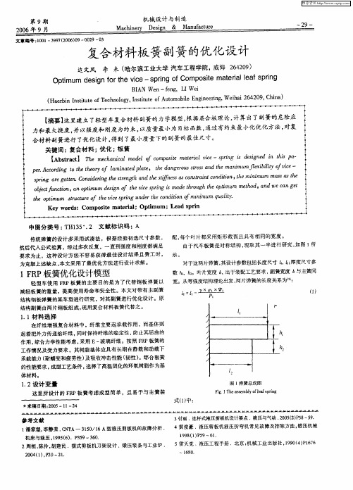
每个叶 片都采用矩形截 面且具有 相同的宽度 。 传统弹簧的设计多采用试 凑法 ,根据经验初 选尺寸参数 , 配 , 由于汽车板簧 是对称结构 , 现取其一半进行研究 , 图 1 如 所 然后代人公式验算 ,经过多次 反复 ,一直到强度和刚度都满足 要求为止 ,这种设计方 法不容易获得最佳 设计结果且费工 时 , 示 。 对于这两片弹簧, 其设计参数包括长度尺寸 f f厚度尺寸参 12 ,; 为克服上述缺点 , 本文采用 了最优化方法进行设计 求解 。
f pn zu ecp gnr e 凡t nm ay 。 u st r t e r d d。o i m ui 胁 m t o hv nu ehC in m i q l. ce f is i t O if n t Ky o sCm otmti; pmm L dpn ewr : op i arlOt u ; e r d s ea i e as i
一2 9一
—
复合材料板簧副簧的优化设计
边文风 李 未( 哈尔滨工业大学 汽车工程学院, 威海 2 40 ) 6 2 9
Op i m e in f rt e vc t mu d sg o ie—s r g o mp st t r le fs r g h p i fCo o i ma e i a p ) n e al n
【 摘要1 这里建立了轻型车复合材料副簧的力学模型, 根据层舍板理论, 计算出了副簧的危险应
力和最大挠度 , 并以强度和刚度为约束 , 以质量最小为 目 函数 , 标 通过有约束最小化优化方法, 对复 合材料 副簧进行 了 优化设计, 得到 了最小质量下的副簧的最佳尺寸。 关键词 : 复合材料 ; 优化 ; 板簧 [ btat h m cD i l oe o m o t m £i i — p n sds nd i ti p一 A s cl e e n 0 m dl fc pse a r l,e sr g i e i e n h 0 r T c o i e 。 t c i g s
不同复合材料板簧的性能比较及结构优化

关键词: 复合材料ꎻ 板簧ꎻ 结构优化ꎻ 有限元分析
中图分类号: TB332 文献标识码: A 文章编号: 2096-8000(2020)06-0035-11
1 引 言
一个重量最小的板簧ꎬ并且能够承受给定的静载而
由于复合材料具有机械性能优异、密度低及易
目标优化模型ꎮ 模型的变量是铺层方案的参数ꎬ子
目标为刚度、强度和质量ꎮ 优化结果表明ꎬ复合叶簧
前ꎬ国内外汽车制造商正致力于研发采用复合材料
的宽度应最大化ꎬ其厚度从板簧眼端向支座抛物线
板簧来替代传统钢材板簧ꎬ在汽车的轻量化、行驶的
增加ꎮ 台架试验结果表明ꎬ复合材料板簧的质量仅
舒适性和操纵的稳定性等方面展开了大量相关研
优的性价比ꎬ重量相比传统钢材板簧减轻了 80%ꎮ 为进一步减轻单片 E 玻纤复合材料板簧的重量ꎬ对其应力较小区域进行变
截面宽度的结构优化ꎮ 结果表明优化后的单片变宽度 E 玻纤复合材料板簧重量相比优化前板簧ꎬ进一步减重 5 2%ꎮ 对钢板
板簧及优化前后的单片 E ̄玻纤复合材料板簧的安全系数、振动频率及应变能等进行综合比较ꎬ结果表明ꎬ结构优化后的单片变
复合材料科学与工程
35
2020 年第 6 期
不同复合材料板簧的性能比较及结构优化
陈广豪ꎬ 梁智洪ꎬ 张芝芳 ∗
( 广州大学广州大学 ̄淡江大学工程结构灾害与控制联合研究中心ꎬ 广州
510006)
摘要: 随着汽车行业日益激烈的竞争和环境问题的不断凸显ꎬ有必要对汽车部件进行优化减重设计ꎮ 本文利用 CATIA
板簧结构ꎬ对于汽车其他金属构件的轻量化设计也
为钢板弹簧的 40%ꎬ且疲劳寿命是其 3 倍ꎮ 此外ꎬ复
复合钢板弹簧的分析与优化
复合钢板弹簧的分析与优化Mahmood M. Shokrieh *, Davood Rezaei 复合材料研究实验室,机械工程系,伊朗科技大学,narmak,德黑兰16844,伊朗理论轻型车辆后悬架系统中使用的四片钢板弹簧是用ANSYS V5.4这种软件进行分析的。
有限结果显示应力和挠度的解析解和实验验证。
使用这种钢板弹簧的结果,通过ANSYS设计出了一种由玻璃纤维与环氧树脂复合制成的弹簧并且得到优化。
主要考虑的是弹簧几何的优化。
其主要目的就是获得一种能够无故障地承载静态外力的轻型弹簧。
这个设计的难点就是受力与位移。
结果表明,最佳的弹簧宽度是以双曲线的规律减小,而厚度从弹簧端孔向轴座线性的增加。
比起钢弹簧,优化复合弹簧应力较低,其自然频率较高和弹簧重量在没有端孔情况下降低80%。
2003埃尔塞维尔科技有限公司版权所有。
关键词:钢板弹簧;复合材料;形状优化;有限元;复合接头;自然频率;悬架系统;组合梁1、介绍为了取代金属零件,复合材料在现在汽车工业中得到广泛使用。
关于应用于汽车的复合材料的多篇论文得到发表。
在这里引用了其中的一些论文,重点是那些涉及复合钢板弹簧的论文。
Breadmore [ 1 , 2]研究了汽车复合结构的应用。
Moris[3]集中把复合材料应用到后方的悬挂系统。
Daugherty[ 4]研究了复合钢板弹簧在重型卡车中的应用。
Yu and Kim[ 5]设计并优化了应用于汽车悬挂的双锥形束钢板弹簧。
Corvi[ 6]调查复合梁设计的初步探讨并用它设计了一个复合钢板弹簧。
弹簧是汽车悬挂中关键的一部分,在尽量减少由于道路违规带来垂直振动,影响和颠簸并创造舒适的乘坐方面是必要的。
钢板弹簧,尤其是纵向型的,是一个可靠和持续的元素在汽车悬挂系统中。
这些弹簧通常由钢板叠加而成,长度由下而上逐步变长,使弹簧在中间抵抗弯曲的地方比较厚而在末端与机体相连的地方比较薄。
弹簧片应支持如图1所示的各种外部力量,但最重要的任务是抵抗变化的垂直力。
汽车板弹簧材料的选择
汽车板弹簧材料的选择在汽车制造过程中,板弹簧是一种重要的悬挂系统组件。
它主要的功能是支撑车身重量和减震,同时也对车辆的操控性和乘坐舒适性有着重要的影响。
而正确选择合适的板弹簧材料对于实现这些功能起着至关重要的作用。
在选择板弹簧材料时,需要考虑多个因素。
首先是弹性模量。
弹性模量是衡量材料弹性变形能力的重要参数,高弹性模量的材料能够更好地支撑车身重量和减震。
常用的板弹簧材料有碳钢、合金钢和复合材料。
碳钢弹簧具有良好的强度和刚度,同时价格相对较低,是一种常用的板弹簧材料。
合金钢弹簧由于添加了特定的合金元素,具有更好的强度和刚度,适用于需要更高强度和更小变形的应用场合。
而复合材料弹簧由于具有较高的弹性模量和较小的重量,可以在一定程度上提高车辆的操控性和燃油经济性。
其次是耐腐蚀性。
汽车在实际使用过程中会遇到多种腐蚀介质,如雨水、路面盐碱等。
为了保证弹簧的正常工作和延长使用寿命,板弹簧材料的耐腐蚀性非常重要。
碳钢弹簧通常需要进行防腐处理,如镀锌、热处理等,以提高其耐腐蚀性。
合金钢弹簧由于合金元素的添加,具有较好的耐腐蚀性,较少需要特殊处理。
而复合材料弹簧由于材料本身的特性,具有良好的耐腐蚀性能。
再次是疲劳性能。
板弹簧在使用过程中经历了反复的加载和卸载过程,需要具有较好的疲劳性能以保证长期的可靠工作。
碳钢弹簧由于其良好的延展性和韧性,通常具有较好的疲劳性能。
合金钢弹簧由于强度和硬度较高,疲劳性能也相对较好。
复合材料弹簧由于其材料的特殊性,具有很好的疲劳性能,可以在长时间的使用中保持较好的弹簧特性。
最后是制造成本。
在选择板弹簧材料时,制造成本也是一个需要考虑的因素。
碳钢弹簧由于材料价格相对较低,制造成本也相对较低。
合金钢弹簧由于合金元素的添加,制造成本相对较高。
而复合材料弹簧由于材料的特殊性,制造成本较高。
综上所述,正确选择合适的板弹簧材料对于汽车的悬挂系统性能和使用寿命有着重要的影响。
选择材料时需要综合考虑弹性模量、耐腐蚀性、疲劳性能和制造成本等多个因素,以满足汽车的实际需求。
复合材料板簧

2、复合材料板簧应用实例
跃野车上的应用
2、复合材料板簧应用实例
前轴横置单簧
2、复合材料板簧应用实例
火车上的应用
2、复合材料板簧应用实例
火车上的应用
3、复合材料板簧应用的意义
减轻汽车重量对汽车的发展具有特殊重要的意义。减 轻汽车自重,不仅可以减少原材料的消耗,降低汽车的成 本,还可以显著降低汽车能源消耗量,减少有害气体的排 放,提高汽车的动力性能。研究表明,汽车质量每减小10 %,可降低6%∼8%的油耗。据相关资料,汽车质量每减 小50kg,则每升燃油行驶的距离可增加1km;若质量减小 10%,则燃油经济性可提高5.5%左右。减轻车辆自重, 实现轻量化设计已成为当今汽车发展的趋势之一。
不同形状的板簧,交叉设计目前应用最多。
4、复合材料板簧的技术发展概况
其它形状的复合材料车用弹簧
蛇形弹簧
螺旋弹簧
4、复合材料板簧的技术发展概况
复合材料板簧的成型工艺
(1) 缠绕工艺是由连续纤维束和基体材料组成的,其中放置纤维束
的转动轴引导纤维沿着轴的方向向前和向后以便于实现所需要的缠绕 角度,纤维的方向是沿着板簧的长度方向的。缠绕工艺在成型恒定厚 度的板簧是非常容易的 ,为了实现所需的纤维含量,材料性能和尺寸 控制,必须在加热加压的情况下进行固化。
4、复合材料板簧的技术发展概况
复合材料板簧的成型工艺
(2)拉挤工艺是通过拉出连续树脂浸渍纤维,通过陶瓷连接去生产一 个给定的交叉区域,可以通过R.F.加热快速固化,拉挤工艺可以生产直 的,连续的区域,但是只要纤维含量是恒定的,如果应用合适的工具可 以生产出形状或弧度变化的板簧,因此当产品脱离结合区后后固化程度 达到90%时,重新塑型的改变量就会很小。
复合材料板簧的优化设计及分析

2 0 年第 1 期 07 2 ( 总第 17 9 期)
农业 装备 与车 辆工 程
AG I U T R LE U P N R C L U A Q IME T& V HIL N I E R N E C EE GN E I G
No 1 2 O .2 O 7
引 言
伴随着油价 的上涨和环境 问题 , 减轻汽 车质 量 以
降低油耗变得 越来越重要 。 为汽车悬架弹性元 件的 作 钢板弹簧在 车体 自重所 占比重 大约 12-/ 5 /0 11。因而 在汽 车板 簧 的发 展方 面 . 内外 汽车 厂 商 和研 究 人 国
员一直都紧紧围绕着轻量化 、 提高驾驶的舒适性 、 稳
收稿 日期 :0 7 0 — 7 20-90
作者简介 : 许长 生( 90 ) 男, 18 一 , 河南信阳人, 读硕士, 在 研究方 向为汽
车零部件数 字化设计。
( oa y1 7 T tl 9 ) l
复合材 料 板 簧 的优 化 设 计及 分 析
许长 生, 高诚辉 , 彭育辉 , 林风功
( 福州大学 机械工程及 自动化学院 , 福建 福州 30 0 ) 5 0 2
摘要 : 根据某汽车钢板 弹簧相 关参数和分析结果 ,用有 限元软件 A Y 设计优化 了一种玻璃纤维增强树脂基复合材 NS S 料 ( gP俗称玻璃钢) GF 板弹簧 来代替原钢板弹簧 , 并对其动态特性及结构应力分布进行有 限元分析 , 结果证明该复合 材料板 弹簧应 力更低 , 固有频率更高, 不计吊耳时弹簧重量减轻 了约 7 %。 5
定 性及 耐 用性 等 方 面进行 了大 量 的研 究 工作 , 出现 了少 片式 、 片式 的板簧 。 中以复合 材料 板簧 成效 单 其
【技术帖】复合材料板簧设计与开发

【技术帖】复合材料板簧设计与开发【摘要】针对于汽车复合材料板簧进⾏产品结构设计、材料选择、⼯艺优化,结合CAE分析仿真计算,掌握板簧铺层设计⽅法。
通过台架试验,研究复合材料板簧测试⽅法,形成相应的技术标准,同时对复合材料板簧进⾏成本分析,为其产业化做铺垫。
主题词:复合材料板簧设计开发1 前⾔⼋⼗年代末,复合材料板簧在美国正式投⼊商业化⽣产,⼴泛应⽤于重型卡车和牵引车上,重量仅为钢材板簧的1/3;德国IFC Composite公司推出⼀种新型板簧来代替奔驰、凌特(Sprinter)、⼤众Crafter车上的传统钢制板簧。
该新型板簧与钢制板簧相⽐,质量减轻40~50%,仅重5.5 kg,疲劳寿命可达20万次以上,⾼于⾦属板簧的16万次。
复合材料板簧已经在全球诸多主机⼚商的产品上得到⼤量应⽤,这些主机⼚包括通⽤、福特、沃尔沃(图1)、戴姆勒-克莱斯勒、依维柯、康沃斯、彼得⽐尔特、国际卡车公司等。
国内在过去的⼆⼗年中,有部分院校、研究院所对复合材料板簧进⾏了探索性研究。
由于还没有完全掌握复合材料板簧的设计及稳定制造技术,现阶段还没有主机⼚量产的报道。
⽬前复合材料板簧中的纤维材料主要为E-玻纤、S-玻纤、⽞武岩纤维和碳纤维[1],本⽂以E-玻纤代替传统材料进⾏板簧结构设计。
图1 复合材料板簧应⽤[2]2 复合材料板簧开发⽬标悬架系统是桥与车架之间的连接纽带,其对整车的⾏驶平顺⾏及操纵稳定性有着重要的影响,同时悬架系统在整车的安全性⽅⾯也是不可忽视的,因此在悬架系统的开发设计中,⼀定要保证板簧输⼊条件的准确性。
⼀般来说,板簧开发设计条件如下。
2.1 整车输⼊条件在板簧开发过成中,整车对悬架系统要求见表1。
2.2 悬架系统输⼊条件除整车要求外,悬架系统对板簧开发设计⾃⾝⽬标制定见表2。
表1 板簧整车开发输⼊参数表表2 板簧开发⽬标3 复合材料板簧开发设计3.1 结构设计⽅法复合材料板簧采⽤单⽚等强度设计,保证板簧沿轴线各截⾯具有相同的强度,以此来降低板簧重量。
汽车复合材料板弹簧的有限元分析及性能测试

汽车复合材料板弹簧的有限元分析及性能测试汽车复合材料板弹簧是现代汽车悬挂系统中的一种新型材料弹簧,它由多层玻璃纤维增强环氧树脂层和铝合金层组成。
该材料弹簧具有体积小、重量轻、抗疲劳性能好、寿命长等优点,为汽车行业带来了重大突破。
本文将从有限元分析和性能测试两个方面对汽车复合材料板弹簧进行探讨。
一、有限元分析有限元分析是一种重要的工程计算方法,可以对汽车复合材料板弹簧的力学性能进行数值模拟,以预测材料弹性变形、疲劳寿命、最大承载能力等重要指标。
通过有限元分析模拟,可以更好地理解和优化汽车复合材料板弹簧的设计和制造。
在有限元分析过程中,需要首先建立汽车复合材料板弹簧的三维模型,并对其进行网格化处理。
接着需要根据弹簧的实际工作环境、外载荷和边界条件等因素,建立合适的力学模型。
然后利用有限元软件进行模拟计算,得到板弹簧的应力、应变、位移等物理量分布规律。
最后根据模拟结果进行分析和评估。
在具体的有限元分析中,需要考虑材料的弹性模量、泊松比、热膨胀系数等参数。
还需要考虑板弹簧的几何结构、截面形状、厚度和叠层方式等因素。
这些因素都会对板弹簧的强度、刚度和疲劳寿命等性能产生重要影响。
因此,有限元分析的结果可以为汽车复合材料板弹簧的设计和制造提供重要参考依据。
二、性能测试为了验证有限元分析的结果,需要进行汽车复合材料板弹簧的性能测试。
性能测试可以直接测量弹簧的实际物理量,如位移、应力、应变等,从而检验有限元分析的准确性和信度。
常见的汽车复合材料板弹簧性能测试方法包括三点弯曲试验、循环荷载试验、疲劳寿命试验等。
其中,三点弯曲试验是最基本的试验,可测量板弹簧的弹性模量、屈服强度、极限承载力等力学指标;循环荷载试验可以模拟板弹簧的实际工作环境,测量其疲劳寿命和断裂机理;疲劳寿命试验则可以评价板弹簧在长期疲劳作用下的耐久性和可靠性。
在性能测试中,需要特别注意汽车复合材料板弹簧的热膨胀系数对测试结果的影响。
因为板弹簧由不同的材料复合而成,各层材料的热膨胀系数不一致,容易引起板弹簧在变温作用下的应力和变形。
- 1、下载文档前请自行甄别文档内容的完整性,平台不提供额外的编辑、内容补充、找答案等附加服务。
- 2、"仅部分预览"的文档,不可在线预览部分如存在完整性等问题,可反馈申请退款(可完整预览的文档不适用该条件!)。
- 3、如文档侵犯您的权益,请联系客服反馈,我们会尽快为您处理(人工客服工作时间:9:00-18:30)。
The Analysis of Composite Leaf Springby Finite Element Methodand Experimental MeasurementsJiashi Wang,Zaike Li and Qibin JiangAbstract The automobile industry has shown increased interest in the replacement of steel spring with E-Glass/Epoxy composite leaf spring due to the higher strength-to-weight ratio,superior fatigue strength and excellent corrosion resistance.In this work the composite leaf spring with the rectangular cross section designed for the commercial vehicle was analyzed by using thefinite element software ABAQUS, and the experimental tests had been conducted to confirm thefinite element analysis results.In thefinite element analysis,the stress analysis and the spring rate computation have been conducted for the composite leaf spring subjected to the full load15,000N.The maximum compressive stress is309.1MPa at the middle of the composite leaf spring,and the safe factor can reach to2.6comparing with the material compressive strength of E-Glass/Epoxy800MPa.The spring rate com-puted from ABAQUS is160N/mm,and the maximum load capacity of the composite leaf spring is approximately34,000N.The measurements of the spring rate and the maximum load capacity were conducted on the composite leaf spring fabricated with the hot molding process method,and they are157.5N/mm and 34,280N paring the results obtained from thefinite element analysis with the experimental measurements,it can be seen that the errors are 1.56%for the spring rate and0.82%for the maximum capacity load,and the main performances of fabricated composite leaf spring have the good agreement with the designed requirements.Keywords Composite materialÁLeaf springÁFinite element analysisÁSpring rateÁMaximum load capacityF2012-E07-004J.Wang(&)ÁZ.LiÁQ.JiangZhuzhou Times New Material Technology Co.Ltd.,Zhuzhou,Chinae-mail:wangjiashi@SAE-China and FISITA(eds.),Proceedings of the FISITA2012World823 Automotive Congress,Lecture Notes in Electrical Engineering195,DOI:10.1007/978-3-642-33835-9_74,ÓSpringer-Verlag Berlin Heidelberg2013824J.Wang et al. 1IntroductionIn order to meet the needs of natural resources and economize energy,weight reduction has been the main focus of automobile manufacturer in recent years[1]. Weight reduction can be achieved primarily by the introduction of better material, design optimization and better manufacturing processes.The suspension leaf spring is one of the potential items for weight reduction in automobile.Because of the higher strength-to-weight ratio,superior fatigue strength and excellent corro-sion resistance,thefiber reinforce plastics(FRP)has shown increased interest in the replacement of steel spring[2].When the spring is made of FRP,such as E-Glass/Epoxy,the weight of the spring can reduce60–70%,which can leads to reduction of the unsprung weight.The elements whose weight is not transmitted to the suspension spring are called the unsprung elements of the automobile,include wheel assembly,axles,and part of the weight of suspension spring and shock absorbers[3].The reduction of the unsprung weight could help in achieving the vehicle with improved riding qualities and increased the fuel efficiency.Therefore, the using of composite leaf spring not only leads to the weight reduction,but also improves the riding qualities.Some works have been conducted with emphasis on the design and application of composite leaf spring,and part of them are reviewed here.Breadmore intro-duced the application of composite structures for automobiles[4,5].Moris con-centrated on using composites in the rear suspension system[6].Yu and Kim[2] designed and optimized a double tapered beam for automotive suspension leaf spring.Corvi[7]investigated a preliminary approach to composite beam design and used it for a composite leaf spring.Rajendran and Vijayarangan developed the genetic algorithms for the design optimization of light weight vehicle composite leaf spring[8],and Shiva Shankar and Vijayarangan[1]investigated the light weight vehicle composite leaf spring concentrated on the end joint analysis and testing.However,there is the limitation for the above research that the designed composite leaf spring is used for the light weight vehicle with static full load below10,000N for one spring.Nowadays,with the development of the auto-mobile industrials,the composite leaf spring with more load-bearing is needed. Meanwhile,the structure,material and the fabricate process are all important. Therefore,it is necessary to investigate the composite leaf spring from simulation and experimental test,as well as verify the effectiveness and safety for the heavier load-bearing composite leaf spring.In this paper the composite leaf spring with rectangle cross section that the constant thickness and width is28980mm is designed for the Commercial vehicle with15,000N full load for one spring.Thefinite element(FE)method is used for the analysis of stress state,computation of numerical spring rate and the maximum load capacity.Meantime,for the validity of the designed spring,the experiment is conducted on the composite leaf spring fabricated by the hot molding process.The measured spring rate and the maximum load capacity arecompared with the FE analysis results.This work develops the application of the composite leaf spring for the automobile industrial.2FE Model of the Composite Leaf SpringAccording to the working and assembly conditions and considering the facility of mass production,the mono spring with constant rectangle cross section is employed for the Commercial vehicle.The geometry structure of the spring can be described as follow.The constant thickness and width is 28980mm,the total length is 1,300mm,the arc radius is 1,080mm.Besides,the full loading is 15,000N,and the designed spring rate is 160N/mm.The 3-D structure can be obtained in the ABAQUS software as shown in Fig.1,and the model is meshed with C3D8I [9]as shown in Fig.2.The dimension of the elements is approxi-mately 5mm,and there are 20,000elements.Because the composite leaf spring is mainly subjected to the moment loading,and the tensile and compressive bending stress is along the longitudinal direction.Therefore,the unidirectional fiber glass is selected to be laid up along the longitudinal direction of the spring,and the material properties of the E-Glass/Epoxy are listed in Table 1.3FE Analysis of the Composite Leaf SpringAccording to the loading condition,the full load 15,000N is applied at the middle of the composite leaf spring,and the stress along the longitudinal direction can be obtained in Fig.3.It can be seen that the maximum stress is at the middle location,compressive stress for the outer surface and tensile stress for the inner surface.Meanwhile,the absolute value of the inner surface stress is larger than the one of the outer surface,which may be due to that the composite leaf spring is the curved beam [10].According to the material properties as given in Table 1,the com-pressive strength of composite material is smaller than tensile strength,so the verify of the stress strength should be based on the compressive strength.The Fig.1The 3-D structure ofcomposite leaf spring The Analysis of Composite Leaf Spring825maximum compressive stress is 309.1MPa at the middle of the composite leaf spring as shown in bining the compressive strength in Table 1and the compressive stress in Fig 3,it can be calculated that the safety factor is 2.6.Spring rate is an important parameter for the spring assembled in the vehicle suspension,and it can be computed from the FE analysis as described as follow.During the FE analysis,the variables such as the applied load and the displacement of the composite leaf spring can be recorded,and the load–displacement curvecan Fig.2Finite element mesh of the composite leaf springTable 1Material properties of E-glass/epoxyPropertiesValue Tensile modulus along X direction (Ex),MPa6,530Tensile modulus along Y direction (Ey),MPa45,000Tensile modulus along Z direction (Ez),MPa6,530Tensile strength,MPa1,100Compressive strength,MPa800Shear modulus along XY direction (Gxy),MPa2,433Shear modulus along YZ direction (Gyz),MPa2,433Shear modulus along ZX direction (Gzx),MPa1,698Poisson ratio along XY direction (NUxy)0.217Poisson ratio along YZ-direction (NUxy)0.217Poisson ratio along ZX-direction (NUxy)0.366Fig.3The stress contouralong the longitudinaldirection of the compositeleaf spring subjected to15,000N826J.Wang et al.be plotted in Fig 4.It can be seen that the slope is almost constant during the analysis process,and the relationship of the load and the displacement can be fitted as the linear function by the origin softwarey ¼160x þ59:6ð1Þwhere x and y represent the displacement and load respectively,and 160should be the spring rate.The second part 59.6should be the deviation which is introduce by the FE simulation and the function fitting.The error can be calculated as 59.6/15,0009100%=0.40%,and it can be neglect in the engineer application.The maximum load capacity is another important parameter for application of the composite leaf spring.Theoretically,when the maximum compressive stress of the composite leaf spring is equal to the compressive strength,the spring will be fractured,and the load should be the maximum load capacity.During the FE analysis,the maximum load is set from 20,000to 70,000N,and the increasing step is set as 2,000N.When the load is increased to 34,000N,the stress state of the composite leaf spring can be obtained as shown in Fig.5.The maximum compressive stress is 819.0MPa,which is just larger than the stress strength 800MPa.Therefore,it is suggested that 34,000is the maximum load capacity of the composite leaf spring.4Experimental TestingThe designed composite leaf spring had been fabricated with the hot molding process method,and the three-point bending experiment is conducted to measure the spring rate.The composite leaf spring is loaded from zero to the prescribed maximum load 15,000N and back to zero with loading speed 200N/s.After five cycles,the load–displacement curves can be obtained as given in Fig.6,and five spring rates were computed from the curves,listed as 160.2,154.9,156.2,157.0Fig.4The load–displacement curve of thecomposite leaf springobtained from ABAQUS The Analysis of Composite Leaf Spring827and 159.2N/mm.The averaged value is computed and taken as the final spring rate,which is 157.5N/paring the experimental results with the value 160N/mm obtained from FE analysis in Sect.3,the error is 1.56%,and they have the good agreement.After the measurement of the spring rate,the maximum load is modified as 70,000N,which is about two times of the maximum load capacity theoretically.The loading speed is set as 200N/s,and the loading process is stopped automatically when the composite leaf spring is fractured.The recorded load–displacement curve is obtained as shown in Fig.7,and the maximum load capacity can be extracted from the curve,which is 34,paring the experimental result with the value 34,000N computed by ABAQUS,the error is 0.82%.Fig.5The stress contouralong the longitudinaldirection of the compositeleaf spring as the maximumcompressive stress close tothe compressivestrength Fig.6The load–displacement curves of thecomposite leaf springobtained from theexperimental tests828J.Wang et al.5ConclusionsThe designed composite leaf spring for the commercial vehicles is analyzed by the FE analysis and experimental test.In the FE analysis,the spring rate and the max-imum load capacity are computed by ABAQUS software,and they are 160N/mm and 34,000N respectively.In the experimental tests,the three-point bending experiments of composite leaf spring fabricated with the hot molding process are conducted,and the tested spring rate and maximum load capacity are 157.5N/mm and 34,paring the results obtained from the FE analysis with the experimental tests,it can be seen that the error is 1.56%for the spring rate and 0.82%for the maximum capacity load,and the main performances of fabricated composite leaf spring meet the designed requirements.In this work the delamination damage between the layers in the composite leaf spring is not considered,which will be investigated in the next step.References1.Shiva Shankar GS,Vijayarangan S (2006)Mater Sci 12:220–2252.Yu WJ,Kim HC (1988)Comp Struct 9:279–3003.Tanabe K,Seino T,Kajio Y (1982)SAE 820403:1628–16344.Beardmore P,Johnson CF (1986)Comp Sci Technol 26:251–2815.Beardmore P (1986)Comp Struct 5:163–1766.Morris CJ (1986)Comp Struct 5:233–2427.Corvi A (1990)Comp Struct 16:259–2758.Rajendran I,Vijayarangan S (2001)Comp Struct 79:1121–11299.Simulia (2007)Abaqus user’s manual,Abaqus Version 6.7.1.Dassault Systemes 10.Hibbeler RC (2010)Mechanics of material.Pearson Education Publications,NewJersey Fig.7The maximum loadcapacity test of the compositeleaf spring The Analysis of Composite Leaf Spring829。