HED-D5多功能电力仪表使用说明书v1.0
电力仪表使用方法ppt课件

3.注意事项 3.1、额定环境条件: (1)室内使用。 (2)装置类别Ⅲ。 (3)污染度2。 (4)海拔2000米。 (5)相对湿度小于80%。 (6)环境温度0-40℃。 3.2、仪表试验导线由双层绝缘或加强绝缘保护 。 3.3、相序测量时,施工人员应防止触电。 3.4、注意!使用仪表前参考使用说明。
2、操作方法步骤及要求(HDE600应用示例) 2.1、模拟4~20MA变送器输出
2. 2、校准纸带/无纸记录仪
2. 3、模拟热电ຫໍສະໝຸດ 的连接图2. 4、校准压力电流(P/I)变送器
2. 5、3线制热电阻测量
2.1.6、校准电流---电流(P/I)变送器
2. 7、校准热电偶变送器
2. 8、测量压力的连接(选配功能)
1.3.4、精度高达±0.05%,并可选±0.01%,±0.02%等级 1.3.5、5位半显示:电流分辨率达0.1μA ;电压分辨率达 0.1μV 1.3.6、自动三角波/阶梯波/正弦波信号输出精度高达0.01% 1.3.7、内置超大容量可充锂电池,并可在线充电 1.3.8、电池容量指示,电池电压过低自动关机保护 1.3.9、温度值可直接测量/输出 1.3.10、手/自动冷端补偿和设定,保存并调用10组设定 1.3.11、数字硅胶按键,
钳形电流表
1、概况及作用 1.1、特点:钳表是一种用于测量正 在运行的电气线路的电流大小的仪表,可在不断电 的情况下测量电流。 1.2、结构及原理:钳表实质上是由一只电流互感器 、钳形扳手和一只整流式磁电系有反作用力仪表所 组成。假定流过导线的电流为一次电流,则就可以 籍由电流感应夹上二次线圈产生的电磁感应,得到 与一次侧 成比例的电流,因此您可以在荧幕上得到 一交流电流的读值。
开相检查灯“R”不亮--------------- 开相端子与红色鳄鱼 夹相连 开相检查灯“S”不亮--------------- 开相端子与黄色鳄鱼 夹相连 开相检查灯“T”不亮--------------- 开相端子与蓝色鳄鱼 夹相连 (4)检查旋转指示器的旋转方向 如果逆时针指示器是亮的,说明三个鳄鱼夹中任意两 相交互连接。 如果顺时针指示器是亮的,而且电源端与红、黄、蓝 鳄鱼夹连接,则相序指示器R-S-T应当均亮。 2.2、电机转向测试仪的操作 (1)确定没有电压存在。
Amprobe DM-5 电能分析仪说明书

Place of Purchase
Date of Purchase Quantity Purchase price
Purchase was for: Business use
Personal use
Offer terms and conditions: Sponsored by Fluke Electronics Corporation, 6920 Seaway Boulevard, Everett WA 98203 and Fluke Corporation Canada, 400 Britannia Road East, Unit 1, Mississauga, ON L4Z 1X9 Canada. Gift with purchase (the “Amprobe Power Promotion”) is available for a “Qualifying Amprobe Purchase” (Amprobe DM-5) made from an authorized Amprobe distributor in the United States or Canada between November 1, 2016 and January 31, 2016. This offer may not be combined with any current or future Fluke Corporation offers. Offer is open to legal U.S. and Canadian residents and/or businesses currently residing or physically located in Canada, the United States and the District of Columbia. Void in Puerto Rico, all other U.S. territories and possessions and overseas military installations and where prohibited or otherwise restricted by law, rule or regulation. All federal, state and local laws and regulations apply. Employees, directors and officers of Fluke Electronics Corporation in the United States and Fluke Canada in Canada (together, the “Sponsor”), its parent companies, affiliated companies, subsidiaries, distributors, representatives, and those persons’ immediate families (parents, siblings, children and spouse) and persons living in the same household (whether related or not) are not eligible to participate in the Promotion. Employees, directors and officers of competing tool manufacturers are also ineligible to participate in the Promotion. A receipt may only be submitted once; receipts submitted more than once are considered invalid. For a list of authorized distributors visit /Amprobe/usen/ WhereToBuy. Redemption requests postmarked after 30 days of purchase will be invalid and will not be returned. Redemption forms must be filled out accurately to qualify. Please allow 6 to 8 weeks after Sponsor’s receipt of a complete redemption form to receive your gift with purchase. This offer is not transferable or assignable. View complete Official Terms and Conditions at .
多功能电力仪表用户手册(LCD_LED)

多功能电力仪表用户手册一、产品简介多功能电力仪表,一种具有可编程测量、显示、RS485数字通讯和电能脉冲变送输出的多功能智能电力仪表,能够完成三相电参量测量(三相电压、三相电流、有功功率、无功功率、视在功率、功率因数、频率等)、四象限电能计量、数据显示、采集及传输,可广泛应用变电站自动化、配电自动化、智能建筑、企业内部的电能测量、管理、考核。
测量精度0.5级,实现LCD现场显示和远程RS-485数字接口通讯,采用标准MODBUS-RTU通讯协议。
二、技术参数三、安装与接线33.2 安装方法(1) 在固定配电柜开开孔尺寸大小的孔;(2) 取出仪表,松开螺丝,取下固定支架;(3) 仪表由前插入安装孔;(4) 插入仪表固定支架,并拧紧螺丝固定仪表。
3.3 端子接线说明:如与仪表壳体接线图不一致,请以仪表壳体接线图为准!(1) 电压输入:输入电压不要高于产品的额定输入电压(100V或400V),否则应考虑使用PT,为了便于维护,建议使用接线排。
(2) 电流输入:11、13、15为电流互感器的进线端,*表示为电流同名端(进线端)。
标准额定输入电流为5A,大于5A的情况应使用外部CT。
如果使用的CT上连有其它仪表,接线应采用串接方式。
去除产品的电流输入连线之前,一定要先断开CT 一次回路或者短接二次回路,为便于维护,建议使用接线排。
(3) 要确保输入电压、电流相序一致,方向一致;否则会出现数值和符号错误(功率和电能)!(4) 仪表可以工作在三相四线方式或者三相三线方式,用户应根据现场使用情况选择相应的接线方式。
一般在没有中心线的情况下使用三相三线方式,在有中心线的情况下使用三相四线方式,三相三线可以只安装2 个CT(A 和C 相),三相四线需要安装三个CT。
仪表内可设置两种接线方式,实际接线方式和表内设置接线方式必须一致,否则仪表的测量数据不正确。
(5) 4、5有功电能脉冲输出,6、7无功电能脉冲输出。
四、编程操作4.1 进入和退出编程状态进入编程状态:在测量显示状态时按住“SET”键约3秒钟,进入密码认证页面,使用“◄”键,“▲”键和“▼”键输入密码(出厂默认用户密码为1111),再按“SET”键就进入编程状态页面。
多功能仪表使用说明书

4.需量
需量是在规定的时间周期内的一个量的平均值,采用固定式区间和滑差式区 间 2 种计算方式。
固定式区间:区间是连续的,仪表在每个区间结束时计算并更新需量。计算 周期设置范围 (1~300 秒)*(1~128) = 640 分钟。
3
滑差式区间:时间间隔是滑动的,仪表按照滑动速度来计算和更新需量。计 算周期设置范围 (1~300 秒)*(1~128) = 640 分钟,增量设置范围(1~300 秒)。
M: 增加默认通道的模拟量;
3.测量
- 三相相电压、线电压 - 三相电流 - 功率 - 功率因数 - 频率 - 需量 - 电能 - 电压总畸变率 - 电流总畸变率 - 2~31th 谐波含量 - 不平衡度 - 电压波峰系数 - 电流 K 系数 - 电话干扰系数 THFF - 可直接接入 277/480V 电压,更高电压可使用电压互感器 - 对于×/1A 或×/5A 电流互感器,其一次值可编程
7.开关量输入 仪表最多支持 8 路开关量输入,具体请参阅第 页选型表。 开关量输入采用干接点输入方式,用于监测如故障报警节点、分合闸状态、
手车位置、电容补偿柜电容投入状态等,开关量输入状态信息可以就地显示或 通过通信接口远传。
8. 继电器输出
5
仪表最多支持 4 路继电器输出,具体请参阅选型表。 每路继电器可在设置菜单中设置工作模式、报警项目、报警范围、回滞量;报 警范围的数据格式为二次电网整型数据。继电器工作模式有:遥控、报警、与 或逻辑运算; 遥控:
五、常见问题及解决办法.....................................24 5.1 通信...............................................24 5.2 测量不准确.........................................25 5.3 电能不准确.........................................25 5.4 仪表不亮...........................................26 5.5 其它异常情况.......................................26
120多功能网络电力仪表使用说明书
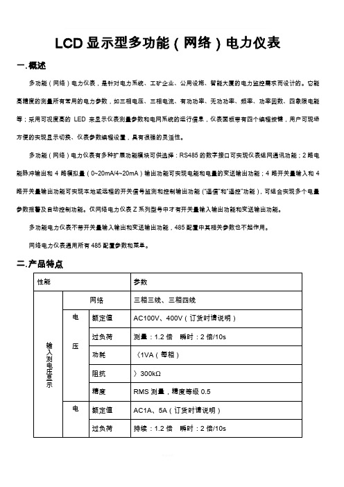
LCD显示型多功能(网络)电力仪表一.概述多功能(网络)电力仪表,是针对电力系统、工矿企业、公用设施、智能大厦的电力监控需求而设计的。
它能高精度的测量所有常用的电力参数,如三相电压、三相电流、有功功率、无功功率、频率、功率因数、四象限电能等;采用可视度高的LED来显示仪表测量参数和电网系统的运行信息,仪表面板带有四个编程按键,用户可现场方便的实现显示切换、仪表参数编程设置,具有很强的灵活性。
多功能(网络)电力仪表有多种扩展功能模块可供选择:RS485的数字接口可实现仪表组网通讯功能;2路电能脉冲输出和4路模拟量(0~20mA/4~20mA)输出功能可实现电能和电量的变送输出功能;4路开关量输入和4路开关量输出功能可实现本地或远程的开关信号监测和控制输出功能(“遥信”和“遥控”功能),可组合实现多个电量参数报警及自动控制功能。
仅网络电力仪表Z系列型号中才有开关量输入输出功能和变送输出功能。
多功能电力仪表不带开关量输入输出和变送输出功能,485配置中其相关参数也不起作用。
网络电力仪表通用所有485配置参数和菜单。
二.产品特点三.安装与接线1.安装尺寸:2.安装方法:1).在固定的配电柜上,选择合适的地方开一个108×108(mm)的安装孔。
2).取出仪表,松开定位螺丝,取下固定夹。
3).将仪表安装插入配电柜的仪表孔中。
4).插入仪表的固定夹,固定定位螺丝。
3.端子接线:1).辅助电源:仪表具备通用的(AC/DC)开关电源输入接口,若不作特殊声明,提供的是220V(AC/DC)或110V(AC/DC)电源接口的标准产品,仪表极限的工作电源电压为AC/DC:80-265V,请保证所提供的电源适用于该系列产品,以防止损坏产品。
A.采用交流电源建议在火线一侧安装1A的保险丝。
B.对于电力品质较差的地区中,建议在电源回路安装浪涌抑制器防止雷击,以及快速脉冲群抑制器。
2).输入信号:产品采用了每个测量通道单独采集的计算方式,保证了使用时完全一致、对称,其具有多种接线方式,适用于不同的负载形式。
多功能电能计multicount D5-x-xxx-MID 快速指南说明书

Quick guide Technical parametersmulticount D5-3P-75A-MIDmulticount D5-3P-1/5A-MIDmulticount D5-2-ES-75A-MIDmulticount D5-2-ES-3P-1/5A-MID 24468_E D E B D A 0270-0322-1_D E -E NENDisclaimer . . . . . . . . . . . . . . . . . . . . . . . . . . . . .5safety instructions . . . . . . . . . . . . . . . . . . . . .5Product liability . . . . . . . . . . . . . . . . . . . . . . . .9disposal . . . . . . . . . . . . . . . . . . . . . . . . . . . . . . .9Menu navigation . . . . . . . . . . . . . . . . . . . .10Commissioning / Check-up . . . . . . . . . .10Technical data . . . . . . . . . . . . . . . . . . . . . . .11Direct connection . . . . . . . . . . . . . . . . . . .12Current transformer /5A und /1A . . . .12Installation instruction . . . . . . . . . . . . . . .12Cable requirement >65A . . . . . . . . . . . . .13Display Language . . . . . . . . . . . . . . . . . . .13Configure of display language . . . . . . .13Bus interface KBR-eBus(only multicount D5-2-xxx-MID . . . . . .14Tariff control . . . . . . . . . . . . . . . . . . . . . . . . .14Current transformer ratio . . . . . . . . . . . .15Current transformer /5A . . . . . . . . . . . . .15Current transformer /1A . . . . . . . . . . . . .16Configuration of current transformerratio . . . . . . . . . . . . . . . . . . . . . . . . . . . . . . . . .16S0 pulse-output . . . . . . . . . . . . . . . . . . . . .16Default settings ex-factory . . . . . . . . . . .17Configuration pulse rate . . . . . . . . . . . . .17Configuration of pulse length . . . . . . . .18S0 pulse-output . . . . . . . . . . . . . . . . . . . . .18Rate per kWh / kvarh . . . . . . . . . . . . . . . .18Length . . . . . . . . . . . . . . . . . . . . . . . . . . . . . .18Peak-Control / Threshold . . . . . . . . . . . . .19 Threshold . . . . . . . . . . . . . . . . . . . . . . . . . . .19 Default settings ex-factory . . . . . . . . . . .19 Response time / release time . . . . . . . .20 Configuration of threshold . . . . . . . . . . .20 Maximum active power: measurement period(only multicount D5-2-xxx-MID) . . . . . .22 Configuration of measurement period . . . . . . . . . . . . . . . . . . . . . . . . . . . . . . .22 Reset of maximum active power . . . . .22 Start / synchronization measurement period . . . . . . . . . . . . . . . . . . . . . . . . . . . . . . .23 Reset minimum and maximum values (only multicount D5-2-xxx-MID) . . . . . .23 Reset power outages . . . . . . . . . . . . . . . .24 Reset of tariff register(only multicount D5-3P-xxx-MID) . . . .24 Reset tariff register . . . . . . . . . . . . . . . . . . .24 Error messages . . . . . . . . . . . . . . . . . . . . . .25 Data backup / power failure . . . . . . . . .27 Calibration pulse /calibration constant . . . . . . . . . . . . . . . . .27 D0 interface accordingto EN 62056-21 . . . . . . . . . . . . . . . . . . . . . .27 Connection-diagram . . . . . . . . . . . . . . . .282Dear customerThank you for choosing a KBR product .To familiarize yourself with the operation and configuration of the device, we recommend that you read this manual carefully .Thiswill enable you to make use of the full range of functions that thishigh-quality product has to offer.The individual chapters explain the technical details of the device and show you how to install and start it up properly to avoid damage .This user manual is included in the scope of delivery of the device and must be accessible to the user at all times (e .g .in the switchgear cabi-net) .Even if the device is resold to third parties, the manual remains an inherent part of the device .Although the utmost care has been taken in writing this user manual, errors may still occur .We would be very grateful if you would notify usof any errors or unclear descriptions you may notice .Yours sincerely,KBR GmbH Schwabach© KBR Kompensationsanlagenbau GmbHMisprints, printing errors and technical changes reserved34EN This manual contains notes that must be observed for your personalsafety and to prevent damage to the equipment . These notes are identified by a warning sign or information symbol, depending on thedegree of hazard they warn about .This means that death, serious physical injury or considerable propertydamage will occur if the appropriate safety precautions are not taken .CAUTIONThis means that minor physical injury or property damage may occur ifthe appropriate safety precautions are not taken .This is an important piece of information about the product, the hand-ling of the product or the relevant part of the user manual to which particular attention should be drawn .The contents of this document have been checked using the hardware and software described .However, deviations cannot be ruled out, meaning that no guarantee can be made for complete agreement .The information provided in this manual is checked on a regular basis; any corrections necessary will be included in the next revision .We appreciate your corrections and comments .In order to prevent operating errors, handling of the device has been kept as simple as possible .This will enable you to start use the device quickly .Be sure to carefully read the following safety instructions .56ENThe applicable DIN/VDE regulations must be observed during installation!Connection to the mains, commissioning and operation of the device may only be carried out by qualified personnel. Qualified personnel as defined in the safety instructions in this user manual are personnel with electrical engineering qualifications, knowledge of the national accident prevention regulations and safety engineering standards as well as of the installation, commissioning and operation of the device .To prevent fire and electric shock, do not expose the device to rain or moisture!Before connecting the device to the power supply, check whether the local power supply conditions comply with the specifications on the device nameplate .Incorrect connection may result in the destruction of the device!When connecting the device, adhere to the information given in the connection diagram (see “Connection diagram”) and that the connec-ting cables are not live . When wiring, always ensure that all cables used are neither damaged nor faulty and observe correct polarity!To ensure proper and safe operation of the device, ensure that it is transported, stored, installed, assembled, and carefully operated and maintained in accordance with the specifications.If the device has any visible damage it is considered unfit for use and must be disconnected from the power supply! Troubleshooting, repairs and maintenance work may only be carried out at our plant or after contacting our customer service team .Unauthorized opening of the device will render your warranty null and void .Correct functioning can no longer be guaranteed!Opening the device may expose live parts .Do not operate open devices under any circumstances!All input and output cables of systems that are at risk from lightning strikes must be fitted with lightning protection.78ENThe multicount D5-xxx-MID should only be used for measuring elec-trical energy and can not be operated outside the specified technical data .When installing or replacing the meter, the conductor, to which the meter is connected, has to be dead (power / voltage off ). Touching live (voltage or power) components is dangerous! Therefore, the appropria-te fuses are to remove and secure . No body shall be able to turn voltage / power on without prior notification. Before opening / disconnect the clamps, short-circuit the secondary circuits of the current transformers . The resulting high voltage on the current transformer is extremely dan-gerous (dangerous to life) and could destroy the current transformer . The usual local security and work rules must be observed . The installati-on of the meter must be carried out by qualified and trained personnel.Der multicount D5-xxx-MID is maintenance free . In case of damage (for example shipping, incorrect connection or storage) repairs may only be done by KBR GmbH .You have purchased a high-quality product.Only components of the highest quality and maximum reliability are used .Each device is subject to long-term testing before delivery .For details on product liability, please refer to our general terms and conditions for electronic equipment .The assured device properties only apply if the device has been opera-ted in accordance with its intended use!Devices that are faulty, obsolete or no longer used must be properly disposed of .If required, we will dispose of the device for you .9ENGo to next unitActive energy, active power etc .M ore information of unitE .g .phase L1, L2, L3, total, Min ./ Max valuesYellow key Service key, on the right side bellow the red terminal cover . To save a configuration, push the service key for 5 seconds.To check for operation:Phase rotationCurrent per phaseNegative energy directionSequence of phase (L1 L2 L3)F or meter with CT’s:- Current Transformer ratio- If present: remove the short circuit on the current transformer Terminal tightening torqueRead-out interface: Correct addressNeutral conductor connected10ENDirect connectionCurrent (I st, I min, I tr, I ref, I max)0 .02 A / 0 .25 A / 0 .5 A / 5 A / 75 A (5(75))Current transformer /5A und /1ACurrent /5A (I st, I min, I tr, I ref, I max)0 .01 A / 0 .05 A / 0 .25 A / 5 A / 6 A (5(6))Current /1A (I st, I min, I tr, I ref, I max)0 .002 A / 0 .01 A / 0 .05 A / 1 A / 1 .2 A (1(1 .2))Installation instructionTorqueS0 pulse output 0,4 Nm (max .2 .5mm2 strand) Tariff control 0,4 Nm (max. 2.5mm2 strand)Cable requirement >65AType: W ire (Cu), cross-section: 35mm²,Outside-Ø 9,55 mmDisplay language can be selected between English and German (Deutsch) .Configure of display languageFor all device variants:After connecting the voltage, the actual language will be shown on the display for about 10 seconds .With the multicount D5-3P -xxx- MID, the language can also be changed in the settings:1) Blue key to Adjustments2) Red key to Language (Sprache)3) Push Service-Key briefly 4) A djust Language by blue key5) S aving: Push Service keyfor 5 seconds, until the display stops to flashENUpon delivery, the address corresponds to the last four digits of the serial number .The address can only be changed via software (KBR eBus)Tariff changeover works with a 230V signal. Neutral cond. on clamp 5 (NE), outer cond .switched on clamp 3 (E3), respectively 4 (E4) .0 = no voltage1 = voltageCurrent transformer ratio can be adjusted from 5/5 to 20‘000/5A and 1/1 to 4’000/1ALeft (blue) key = Change of digit / number Right (red) key = Go to next digit / number Current transformer /5AAABCC : 5AAA adjustable in steps of 1B adjustable in steps of 1CC adjustable in steps of 5ENCurrent transformer /1AYYYY : 1AY adjustable in steps of 1Configuration of current transformer ratio1) Blue key to Transformer ratio2) Push service key briefly3) Adjust secondary current by blue key4) Go to primary current by red key5) Adjust first two digits by blue key6) Go to next digit by red key7) Adjust digit by blue key8) Go to next digit by red key .9) Adjust next two digits by blue key .10) Saving: Push Service key for 5 seconds, until digits are not blinkingS0 pulse-outputThe four S0 pulse-outputs are designed according to EN62053-31(DIN 83864). Pulse rate and pulse lengths can be configured by the keys .Default settings ex-factory1 .S0 Output = Active Energy Import (12+13)2 .S0 Output = Reactive Energy Import (10 + 11)3 .S0 Output = Active Energy Export (8 + 9)4 .S0 Output = Reactive Energy Export (6 + 7)conn. CTDirectPulse rate 1000 Imp ./kWh 10 Imp ./kWh 40ms120ms lengthPulseThe multicount D5-3P-xxx-MID only has one pulse-output for active energy import .Configuration pulse rate1) Blue key to Adjustments2) Red key to S0 Pulse Rate3) Push service key briefly4) Move decimal place by blue key Example 1000 .000 = 1000 Impulse5) Saving: Push Service key for 5 seconds, until digits are not blinkingENConfiguration of pulse length1) Blue key to Adjustments2) Red key to S0 Pulse Duration3) Push service key briefly4) Adjust pulse length by blue key5) Saving: Push Service key for 5 seconds, until digits are not blinkingS0 pulse-outputOpto Power MOSFET5 – 230 VAC or VDC, max .90mARate per kWh / kvarh0 .001, 0 .01, 0 .1, 1, 10, 100, 1000, 10’000LengthAdjustable from 4 to 250 milliseconds in steps of 2 ms .ThresholdThe following values can be chooses as a threshold:- Active Power - Reactive power - Apparent power - Current total - Current per phase L1 / L2 / L3Only one threshold can be defined for all 4 outputs. Only positive values are detected .Default settings ex-factoryThreshold: 5 .000 kWStatus: Not activeENResponse time / release timeThe response and release time is adjustable between 0 and 9999seconds .Response time: Time, until contact switchesRelease time: T ime, until contact switches after threshold isnot exceeded anymore .The threshold function can be assigned to any output S0 .Configuration of threshold1) Blue key to Adjustments2) Red key to Assignment Output X3) Push service key briefly4) Adjust to Threshold by blue key5) Saving: Push Service key for 5 seconds, until digits are not blinking6) Red key to Unit Threshold7) Push service key briefly8) Select desired unit by blue key9) Next by red key10) Adjust Threshold by blue key11) Go to next digit by red key12) Saving: Push Service key for 5 seconds, until digits are not blinking13) Red key to Threshold Time till ON14) Push service key briefly15) Adjust digit by blue key16) Go to next digit by red key17) Saving: Push Service key for 5 seconds, until digits are not blinking18) Red key to Threshold Time till OFF19) Push service key briefly20) Adjust digit by blue key21) Go to next digit by red key22) Saving: Push Service key for 5 seconds, until digits are not blinkingENConfiguration of measurement period1) Blue key to Adjustments2) Red key to Measurement period3) Push service key briefly4) Adjust time by blue key5) Saving: Push service key for 5 secondsReset of maximum active power1) Blue key to Reset Register2) Red key to Max .Active Power3) Push service key briefly4) Set to RESET by blue key5) Perform reset: Push service key for 5 secondsStart / synchronization measurement periodSynchronization takes place by using a 230VAC control signal .In normal operation mode, voltage is connected to input E1, input E2 is dead (without voltage) .To start a new measurement period, disconnect voltage from E1 and connect voltage to E2 .For security reasons a voltage change has to take place at both inputs E1 and E2 .Normal mode Start new measurementE1E2E1E21 0010 = No voltage 1 = Voltage1) Blue key to Reset Register2) Red key to Min/Max Register3) Push service key briefly4) Set to RESET by blue key5) Perform reset: Push service key for 5 secondsReset power outages1) Blue key to Reset2) Red key to Power outages3) Push service key briefly4) Set to RESET by blue keyEN5) Perform reset: Push service key for 5 secondsThe multicount has a resettable tariff register. The resettable register is indicated by and arrow above the unit (kWh) .Reset tariff register1) Blue key to Reset Register2) Red key to Active energy NO RESET3) Push service key briefly4) Set to RESET by blue key5) Perform reset: Push service key for 5 secondsIf an internal error appears, an error message is displayed .F .F .0(00000000) No error, meter okF .F .0(xxxxxxx0) Meter calibratedF .F .0(xxxxxxx1) Meter not calibratedF .F .0(xxxxxxx8) C alibration release, meter is calibratedand can be re-calibrated .F .F .0(xxxxxxx9) C alibration release, meter is not calibrate andcan be calibrated now .F .F .0(xxxxxxxF) M eter initializes again .Default parametersare loadedF .F .0(xxxxxx0x) Meter in normal modeF .F .0(xxxxxx1x) Meter in service modeF .F .0(xxxxx0xx) Checksum Micro FLASH and EEPROM OKF .F .0(xxxxx1xx) Error in checksum Micro FLASHF .F .0(xxxxx2xx) Error in checksum EEPROMF .F .0(xxxxx3xx) Error in checksum FLASH and EEPROMF .F .0(xxxx0xxx) Micro RAM and STACK OKENF .F .0(xxxx1xxx) Error checksum Micro RAM .F.F.0(xxxx2xxx) Error Micro STACK (Overflow).F .F .0(xxxx3xxx) Error checksum Micro RAM andError Micro STACK .F .F .0(xxx0xxxx) Micro OKF .F .0(xxx1xxxx) Error in MicroF .F .0(xx0xxxxx) Hardware OKF .F .0(xx1xxxxx) Hardware ErrorF .F .0(x0xxxxxx) Real Time Clock (RTC) OKF .F .0(x1xxxxxx) Error in Real Time ClockF .F .0(0xxxxxxx) Real Time Clock setF .F .0(1xxxxxxx) Real Time Clock default datum / timeTo prevent data loss in case of power failure, all relevant data are stored in non-volatile EEPROM .This takes place if voltage is falling below a defined level. Also automatically every 24 hours to save all relevant data in non-volatile EEPROM .The red LED on the front is proportional to the active power .The pulse constant is 10 Imp ./WhThe pulse duration is 2msec .Pulses are sent for energy direction import and exportThe D0 (optical) interface is located on the front, right next to the display .The multicount D5-xxx-MID have a serial D0 interface accordingto EN 62056-21. The D0 interface can be configured as bidirectional (Mode A or C) or as a unidirectional (D0 mode) communication interface .ENL1L2L3NSteuereingängeL1 N SteuereingängeENSteuereingängeL1L2L3NSteuereingängeN31Am Kiefernschlag 7 D-91126 Schwabach T +49 (0) 9122 6373 - 0F +49 (0) 9122 6373 - 83E info @ kbr .d ewww.kbr.deKBR Kompensationsanlagenbau GmbH。
HD五位双显称重仪表说明书
报警参数在第 1 组参数,无报警功能的仪表没有该组参数。
① 按住设置键 第 1 个参数的符号
2 秒以上不松开,进入设置状态,仪表显示
② 按 键可以顺序选择本组其它参数
③ 按 键调出当前参数的原设定值,闪烁位为修正位
④ 通过 键移动修改位, 修改为需要的值
键增值、
键减值,将参数
⑤ 按 键存入修改好的参数,并转到下一参数。若为本组最 后 1 个参数,则按 键后将退出设置状态
内容 输入信号选择 显示小数点位置选择
量程下限 量程上限 零点修正值 满度修正值 数字滤波时间常数 设定值显示选择 输出信号选择 变送输出下限 变送输出上限
地址 取值范围 说明
30H
ห้องสมุดไป่ตู้
0 ~ 19
7.1
31H
注2
7.1
32H -19999~99999 7.1
33H -19999~99999 7.1
34H -19999~99999 8
35H 0.5000~1.5000 8
36H
1 ~ 20
7.1
3DH
0~4
7.1
4DH
1~ 3
7.3
4EH -19999~99999 7.3
4FH -19999~99999 7.3
注 1:H、L 两种方式。H:上限报警, L:下限报警。 注 2:进入后,按 键,小数点依次循环左移。
14
6、操作
6.1 面板及按键说明(以 A-H2 规格的仪表为例)
4 8:通信接口 S0:无通信接口 S1:RS 232 接口 S2:RS 485 接口
4 9:输入电压 AC:220V DC:24V
6
安装与接线
多功能电力表液晶说明书

PD系列(LCD)多功能网络(谐波)电力仪表用户手册施瑞德电气有限公司目录1.产品特点 (3)2.仪表型号 (3)3.型号说明 (4)4.主要技术参数 (5)5.面板说明及信息 (6)6.操作流程 (10)7.操作说明 (13)8.输出功能 (15)9.通信协议 (16)10.外形及安装开口尺寸…………………………………………………………………2011.接线图 (21)一、产品特点⊙测量项目:电压/电流/有功功率/无功功率/频率/功率因率/四象电能等,共28个电参数⊙4路开关量输入和4路开关量输出;输入/输出全隔离⊙具有效值测量;⊙具有可编程变送输出功能,可对电压/电流/有功功率/无功功率/频率/功率因数变送输出⊙具有RS485数字接口,采用Modbus RTU通信协议⊙具有二路电能脉冲输出;四路可编程报警;显示编程设置输入参数⊙对有功电度/无功电度具有掉电保护功能⊙具有2-31次谐波测量功能⊙具有需量测量功能⊙具有8时段4费率功能;该系列仪表可广泛应用于控制系统、SCADA系统和能源管理系统中、变电站自动化、配电网自动化、小区电力监控、工业自动化、智能建筑、智能型配电盘、开关柜中;有安装方便、接线简单、维护方便、工程量小、现场可编程设置输入参数的特点。
警告如果不按说明书操作会发生意外,而且会导致产品毁坏。
二、仪表型号1、PD系列系列多功能电力仪表是针对电力系统、工矿企业、公共设施、智能大厦等电力监控、智能控制、计量考核的应用场合设计的高精度、高可靠、高性价比的智能配电仪表产品。
该系列仪表采用高可靠的MCU设计,可以测量三相电网中所有电量参数如三相电压(相/线)、三相电流、有功功率、无功功率、功率因数、电网频率、需量和双向电能计量,具有标准电能脉冲输出和RS485通讯接口,可选多种扩展功能模块。
2、PD系列系列(LCD显示)为标准产品,具有测量和计量功能,配置电能脉冲输出和通讯接口; PD系列系列(LCD显示)在标准功能的基础上增加直流变送输出、开关输入监测、继电器输出等功能;PD系列系列(LCD显示)采用段码式液晶屏菜单切换显示,并具有复费率电能计量和谐波测量等功能;外形代号指针表型号面框尺寸开孔尺寸2 42方形120*120 111*1119 96方形96*96 91*913 80方形80*80 76*76A 72方形72*72 67*67四:主要技术参数网络三相三线、三相四线AC 100V、400V(订货时请说明)电压额定值持续:1.2倍瞬时:2倍/10S 电压过负荷电压功耗<1VA (每相)电压阻抗电压精度RMS测量、精度等级0.5AC 1A 5A(订货时请说明)电流额定值电流过负持续:1.2倍瞬时:10倍/10S荷电流功耗<0.4VA (每相)电流阻抗<20mΩ电流精度RMS测量、精度等级0.5 频率45~60Hz、精度0.1Hz 功率有功、无功、视在功率、精度0.5% 电能四象限计量,有功精度0.5%,无功精度1% 显示可编程设置、切换、循环3排LCD显示电源工作AC/DC 100~240V 范围电流功耗标准RS-485、MODBUS-RTU协议输出数字接口脉冲输出2路电能脉冲输出(光耦继电器)4路开关量输入(干结点方式)开关量输入报警输出4路开关输出,250VAC/3A或30VDC/5A 模拟量输4路模拟量变送输出,4-20mA DC 出工作环境温度:-10~55℃湿度:<85%RH 储存环境-20~75℃耐压输入和电源1600VAC,输入和输出1600VAC,电源和输出1600VAC绝缘输入、输出、电源对机壳>5M Ω尺寸(mm ) 96W х96H х100L 重量0.6kg五、面板说明及信息显示:三相电压,三相电流,有功功率、无功功率、视在功率,功率因素,频率、电压、电流不平衡度,有功功率、无功功率、视在功率需量,线三相电压最大值,线三相电流最大值,有功、无功、视在功率最大值,线三相电压最小值,线三相电流最小值,有功、无功、视在功率最小值,三相电压谐波值,三相电流谐波值。
- 1、下载文档前请自行甄别文档内容的完整性,平台不提供额外的编辑、内容补充、找答案等附加服务。
- 2、"仅部分预览"的文档,不可在线预览部分如存在完整性等问题,可反馈申请退款(可完整预览的文档不适用该条件!)。
- 3、如文档侵犯您的权益,请联系客服反馈,我们会尽快为您处理(人工客服工作时间:9:00-18:30)。
HED-D5多功能电力仪表使用手册(2011.09.V1.0版)目录一、概述 (2)二、技术参数 (2)2.1辅助电源 (3)2.2信号输入 (3)三、编程和使用 (3)3.1按键定义 (3)3.2测量显示 (3)3.3页面显示示意图 (4)3.4编程菜单的组织结构图 (6)3.5菜单结构说明 (7)3.6面板字符和显示说明 (8)3.7使用要求和参数设置方法 (9)四、功能输出 (10)4.1电能计量和脉冲输出 (10)4.2数字通讯 (10)4.2.1概述 04.2.2MODBUS-RTU通讯协议 (12)4.2.3通讯报文格式 (12)4.2.4MODBUS地址信息表 (13)4.2.5浮点型数据计算方法 (13)4.2.6通迅报文举例 (14)五、接线图 (16)H型:120*120接线图 (16)A型:96*96接线图 (17)K型:80*80接线图 (18)F型:72*72接线图 (19)六、常见问题及解决办法 (20)HED-D5多功能电力仪表用户手册一、概述HED-D5多功能电力仪表是一种具有可编程测量、显示、数字通讯和电能脉冲变送输出等功能的多功能电力仪表,能够完成电量测量、电能计量、数据显示、采集及传输,可广泛应用变电站自动化,配电自动化、智能建筑、企业内部的电能测量、管理、考核。
测量精度为0.5级、实现LED 现场显示和远程RS-485电能测量范围有功无功电度测量范围0~100万度,超过此数值电度从0开始计数2.1 辅助电源:HED-D5多功能电力仪表具备通用的(AC/DC)电源输入接口,若不作特殊声明,提供的是AC/DC85~270V电源接口的标准产品,请保证所提供的电源适用于该系列的产品,以防止损坏产品。
注:采用交流供电时,建议在火线一侧安装1A保险丝。
电力品质较差时,建议在电源回路安装浪涌抑制器防止雷击,以及快速冲群抑制器2.2 输入信号:HED-D5多功能电力仪表采用了每个测量通道单独采集的计算方式,保证了使用时完全一致对称,其具有多种接线方式。
适用于不同的负载形式。
2.2.1 电压输入:输入电压应不高于产品的额定输入电压(100V或400V),否则应考虑使用PT,在电压输入端须安装1A保险丝。
2.2.2 电流输入:标准额定输入电流为5A,大于5A的情况应使用外部CT。
如果使用的Ct上连有其它仪表,接线应采用串接方式,去除产品的电流输入连线之前,一定要先断开CT一次回路或者短接二次回路。
建议使用接线排,不要直接接CT,以便拆装。
2.2.3 要确保输入电压、电流相对应,顺序一致,方向一致;否则会出现数值和符号错误!(功率和电能)2.2.4 仪表输入网络的配置根据系统的CT个数决定,在2个CT的情况下,选择三相三线两元件方式;在3个CT的情况下,选择三相四线三元件方式。
仪表接线、仪表编程中设置的输入网络NET应该同所测量负载的接线方式一致,不然会导致仪表测量的电压或功率不正确。
其中在三相三线中,电压测量和显示的为线电压;而在三相四线中,电压测量和显示为电网的相电压。
三、编程和使用3.1按键定义回车键:密码进入确认及数字参数修改确认。
菜单键:用于选择菜单界面、退出功能和返回上级菜单功能。
向右键:测量显示时做转换功能,修改数据时此键为数字加键(从0-9999循环)向左键:测量显示时做转换功能,修改数据时此键做数字减键(从0-9999循环)3.2 测量显示可测量电网中的电力参数有:Ua、Ub、Uc、(相电压);Uab、Ubc、Uca (线电压)Ia、Ib、Ic(电流);Ps(总有功功率);Qs(总无功功率);PFs (总功率因素);Ss(总视在功率);FR(频率)以及有功电能、无功电能所有的测量电量参数全部保存仪表内部的电量信息表中,通过仪表的数字通讯接口可访问采集这些数据。
而对于不同的型号的仪表,其显示内容和方式却可能不一致,请参考具体的说明。
所有的电量参数的计算方法采用如下公式的数字化的离散方法,具体为:其中P>0,累计的有功电能量是有功电能吸收,P<0,累计的有功电能是有功电能释放Q>0,累计的无功电能是无功电能感性,Q<0,累计的无功电能是无功电能容性3.3 页面显示示意图:可设置DISP控制字用来编程设置通常状态下显示内容,DISP=1(三相电流),2(三相电压),3(有功功率),4(功率因素),5(视在功率),6(无功功率),页面内容说明disp=1分别显示电压Ua、Ub、Uc(三相四线)和Uab、Ubc、Uca(三相三线)左图中Ua=326.7V、Ub=326.8V、Uc=326.6V,K灯亮时表示KV。
三相三线接线仪表显示线电压三相四线接线仪表显示相电压disp=2 显示三相电流Ia,Ib,Ic单位为A。
左图中Ia=18.77A、Ib=18.76A、Ic=18.78A。
K灯亮时表示KA 。
页面内容说明disp=3 显示有功功率(W)、无功功率(var)、功率因数PF。
左图中P=1645W、Q=951var、PF=0.5K灯亮时表示KW或Kvar。
disp=4 显示频率(Hz)左图中频率为:50Hzdisp=5 显示正有功电能值,第二排数码管是高4位,第三排是低4位,形成一个8位值。
左图表示有功电能值为:369587.28kWh。
按键:可切换显示正有功电能和负有功电能。
:正有功电能:负有功电能disp=6 显示正有功电能值,第二排数码管是高4位,第三排是低4位,形成一个8位值。
左图表示有功电能值为:369587.28kWh。
按键:可切换显示正有功电能和负有功电能。
:正有功电能:负有功电能注意:1.按可以切换查看不同页面的电量信息。
2.如页面显示值disp设置为0,则自动循环显示各页面,页面切换时间为5S。
3.4 编程菜单的组织结构,用户可根据实际情况选择适当的编程设置参数3.5 菜单结构说明3.6 面板字符和显示说明3.7 使用要求和参数设置方法:⑴使用要求:所有的仪表在第一次使用时,请检查仪表的参数同所在配电系统中参数是否一致,仪表后面的标签中都标注了仪表出厂的设置参数;如果不一致可自行修改仪表内部参数,使其满足配电系统中的要求。
⑵参数设置方法:例1、仪表输入信号为三相三线,输入电压是10KV/100V,输入电流是300A/5A,设置方法如下:例2、修改仪表通讯参数:仪表地址号码为10、波特率为9600、数据格式为8 个数据位、1个停止位,偶校验方式。
设置方法如下:四、功能输出4.1计量和脉冲输出:HED-D5多功能电力仪表提供有功/无功电能计量,2路电能脉冲输出功能和RS485的数字接口来完成电能数据的显示和远传。
仪表3排12位LED实现有功电能(正向)、无功电能(感性)1次侧数据的显示,下图1中表示正向有功电能数=369587.28kWh(度);集电级开路的光耦继电器的电能脉冲(电阻信号)实现有功电能(正向)和无功电能(反向)远传,采用远程计算机终端、PIE、DI开关采集模块,采集仪表的脉冲总数来实现电能累积计量(国家计量规程:标准表的脉冲误差比较方法)。
1)电气特性:集电极开路电压VCC≤48V、电流Iz≤50mA。
2)脉冲常数:3200imp/kWh。
其意义为:当仪表累积1kWh时脉冲输出个数为3200个,需要强调的是1kWh为电能的2次测电能数据,在PT、CT的情况下,相对的N个脉冲数据对应1次测电能为1kWh X 电压变比PT X 电流变比CT。
3)应用举例:PLC终端使用脉冲计数装置,假定在长度t的一段时间内采集脉冲个数为N 个,仪表输入为:10kV/100V、400A/5A,则该时间段内仪表电能累积为:N/3200X100X80度电能(下图2中表示无功电能正向,值为7321.45度无功电能)。
4.2数字通讯4.1概述HED-D5多功能电力仪表提供串行异步半双工RS485通讯接口,采用MODBUS-RTU通信协议,各种数据信息均可在通讯线路上传送。
在一条线路上可以同时连接多达32个仪表,每个仪表均可以设定其通讯地址(Address NO.)和波特率,通讯连接线应使用带有铜网的的屏蔽双绞线,线径不小于0.5mm2。
布线时应使用通讯线远离强电电缆或其他强电场环境,组网时推荐采用T型网络的连接方式。
不建议采用星形或其他的连接方式。
4.2.2 MODBUS-RTU通讯协议MODBUS协议约定在一根通讯线上采用主从应答方式的通讯连接方式。
首先,主计算机的信号寻址到一台唯一地址的终端设备(从机),然后,终端设备发出的应答信号以相反的方向传输给主机,即在一根单独的通讯线上信号沿着相反的两个方向传输所有的通讯数据流(半双工的工作模式)。
MODBUS协议只允许在主机(PC、PLC等)和终端设备之间通讯,而不允许独立的终端设备之间的数据交换,这样各终端设备不会在它们初始化时占据通讯线路,而仅限于响应到达本机的查询信号。
4.2.2.1主机查询:查询消息帧包括设备地址码、功能码、数据信息码、校验码。
地址码表时要选中的从机设备功能代码告之被选中的从设备要执行何种功能,例如功能代码03或者04是要求从设备读寄存器并返回它们的内容;数据段包含了从设备要执行功能的其它附加信息,如在读命令中,数据段的附加信息有从何寄存器开始读的寄存器数据;校验码用来检验一帧信息的正确性,为从设备提供了一种验证消息内容是否正确的方法,它采CRC16的校准规则。
4.2.2.2 从机响应:如果从设备产生一正常回应,在回应消息中有从机地址码、功能代码、数据信息码和CRC16校验码。
数据信息码包括了从设备收集的数据:如寄存器值或状态。
如果有错误发生,我们约定是从机不进行响应。
4.2.2.3 数据传输方式传输方式是指一个数据帧内一系列独立的数据结构以及用于传输数据的有限规则,下面定义了与MODBUS协议-RTU方式相兼容的传输方式。
每个字节的位:1个起始位、8个数据位、(奇偶校验位)、1个停止位(有奇偶校验位时)或2个停止位(无奇偶校验位时)。
4.2.3.1 地址码:帧的开始部分,由1个字节(8位二进制码)组成,十进制为0~255,在我们的系统中只使用1~247,其它地址保留。
这些位标明了用户指定的终端设备的地址,该设备将接收来自与之相连的主机数据。
每个终端设备的地址必须是唯一的,仅仅被寻址的终端会响应包含了该地址的查询,当终端发送回一个响应,响应中的从机地址数据告诉了主机那台终端与之进行通信。
4.3.3.2 功能码:告诉终端执行何种功能。
下表列出HED-D5多功能电力仪表所支持的功能码,以及它们的意义和功能。
4.2.3.3 数据码:包含了终端执行特定功能所需要的数据或者终端响应查询时采集到的数据。
这些数据的内容可能是数值、参考地址或者设置值。