WDT-01漏水传感器说明书
WD 产品说明书 V2.0

北京鸿远鹏奥科技有限公司二、北京鸿远鹏奥科技有限公司公司总机:+86-010-******** 传真:+86-010-********销售热线:+86-010-********电子邮件:*******************公司网址:公司地址:北京市海淀区西三旗金燕龙大厦 邮政编码:100096WD 产品用户手册Version 2.0本手册指所有权由北京鸿远鹏奥科技有限公司独家拥有。
未经本公司之书面许可,任何单位和个人无权以任何形式复制、传播和转载本手册之任何部分,否则一切后果由违者自负。
注意:本手册仅为WD 系列配置手册,本公司拥有对本手册的最终解释权,并保留对其描述的产品改进的权利。
WD-400 温度监测表主要特点:l测温范围-55℃~+125℃l温度分辨率0.0625℃l可设置上限/下限报警l具有RS485通讯接口l4位LED显示l10-40Vdc宽供电范围WD400温度监测表具有温度采集、显示、报警、控制、通讯功能于一体,仪表采用TDC数字温度传感(DS 18B2 0),测温精度:±0 .5℃,温度监测范围:-55℃~+125℃,温度分辨率:12位(0.0625℃)。
显示功能:WD400温度监测表采用4位红色LED数码管,用于显示温度数值,两个状态指示灯用于指示报警和通信状态。
报警和控制功能:WD400可设定报警温度点,一个继电器的无源接点输出,可用于报警指示或控制外部设备,如排风扇、加热器等设备,实现温度控制功能。
通信功能:WD400温度监测表配有标准的RS485总线接口,单一总线上可连接128台WD400仪表,每台WD400仪表具有独立的8位地址,该地址号可通过仪表面板上的按钮设定。
隔离性能:WD400具有高电气隔离性能,保证了仪表安全稳定的工作。
温度传感器、通信接口和供电电源之间具有电气隔离,这一性能,保证了仪表即使在恶烈的强电磁场干扰环境下,也能可靠工作。
宽供电范围:采用10-40Vdc的供电设计,可以对温度监测表进行远距离供电,而不受线路压降的影响,单一电源即可对分布现场的仪表供电,适合分散点的温度监测。
管道漏水漏气漏油检测仪说明书.
2、能使主机和从机同时处于‘←’标示状态,出现此误操作后,可按主机的复位键调整。
●音量控制
系统分四级音量控制。当系统处于全频状态时,如果液晶屏上的8个动态柱大多数处于封顶状态,说明传感器输入信号过强,应减小音量(按音量-键,使液晶屏的8个动态柱处于参差不齐状,则为最佳工作状态。否则将会影响测试的准确性。当使用耳机监听时,应按下复位键。当液晶屏上出现北京普立华研制字样时,系统此刻处于待命状态,音量应由小到大渐进,以期得到最佳监听效果。
●通信功能
当系统处于全频或单频状态时,在液晶屏的中右边出现‘→’标示,系统自动通过RS232口实时将8个频段的数据向上位机或同类机进行通信(波特率为9600,以便上位机进一步分析、处理或存储。当按下通信键时,在液晶屏的中右边出现‘←’标示,可接收上位机或另一台同类机发送来的数据。
两台同类机通信演示:将两台机通过RS232口用RS232通信线相连,其中一台主机
●模拟放大、滤波功能
由于漏水频带一般均处在1200HZ以内,为了抑止各类噪声的干扰,系统将整个漏水声频带划分为8个频段(F1~F8,中心频率分别是:150HZ,240HZ,310HZ,380HZ, 500HZ,650HZ,820HZ,1050HZ。声音传感器接收到的漏水声模拟电信号经音量控制器后送入音频放大器放大,由8选1模拟滤波器自动对8个频段进行分时检测,然后进入A/D转换器采样,量化后再由微处理器进行处理。
●全频测试功能
当按下全频键后,系统具有对8个频段(F1~F8同时实时测试功能,液晶屏上8条动态柱表示了8个频段信号的幅度值,每个动态柱上方用两位十进制数表示出瞬时幅度值的大小。直观的动态波形为操作人员快速寻找漏水点的方位提供了极大的方便。
Seeed Studio S-TH-01 空气温度湿度传感器说明书

User ManuelAir Temperature and Humidity Sensor-Data SheetProduct Model:S-TH-01Version:V1.0Contents1.Background and Product Introduction (3)1.1.Background (3)1.2.Product Introduction (4)2.Sensor Cables (5)3.Model and Size (6)4.Installation and Measurement (7)5.The relationship between output and Humidity,Temperature (8)6.RS485Communication and Protocol (9)6.1.Modbus Communication Protocol (9)6.2.Modbus register (10)6.3.Detail of Modbus register (12)6.4.CRC16Validation and sample code (15)6.4.1.Function3communication samples (15)6.4.2.Function4communication example (16)6.4.3.Function16communication example (18)6.4.4.CRC16Verification algorithm and routine (19)ing the serial port to adjust the software communication (23)1.Background and Product Introduction1.1.BackgroundAccording to the physiologist,the temperature and humidity of the environment can directly affect the thermoregulation and heat conduction of human body.The somatosensory of human body can reflect on the level of mental status and agility of conceptual activities.It can be a vital factor that influences our efficiency of working and study.As experimental analytics,the most comfortable indoor temperature will be18degrees and humidity would40%-60%.There will be specific standard for temperature and humidity with different locations and usage.Therefore,reasonable humidity and temperature controls become necessary.1.2.Product Introduction.Provide high accuracy measurement data..Compact temperature,humidity and dew point measurement..Standardling Output..RS485output and Modbus-RTU Protocol..Multiple installation and user-friendly..Outstanding and reliable stableness with high cost performance.SpecificationSignal Output RS485ModBus ProtocolPower supply 3.6-30V/DCCurrentConsumption4mA@24V DCHumidityMeasurement0-100%saturation,resolution0.01%Accuracy:±3%RH RangeTemperatureMeasurement-40~80℃,resolution:0.01℃,Accuracy±0.3℃RangeIP Rating IP54OperatingTemperature-40~85℃InstallationMethods Wall-mounted Installation and Tube installationCable Length2MConnectionMethods Aviation connector and Hook-up wire2.Sensor CablesSensor Cables specRed(V+):VCC+power supplyBlack(G):VCC-power groundYellow(T+):RS485+/A/T+WhiteT-):RS485-/B/TThe configuration for the module,such as,Baud rate,Verification,communication protocol etc.is saving in the module named EEPROM.Sometime,the module accidentally forgets the configuration and it cause failing on communication.In order to fix this problem,there is a bottom on the module.Holding the bottom for3seconds and the internal light turns off,the module will be setting to default configuration below:1.Default Modbus address is1or42munication configuration:9600,N,8,1(9600bps,No verification,8data bits,1stop bit)munication Protocol:Modbus-RTU3.Model and Size4.Installation and Measurement Wall-mounted or tube design installation:5.The relationship between output and Humidity,TemperatureModel Parameter RelationshipRS485interface and ModbusProtocol Temperature:-40-80℃Temperature=Temperature register/100.Forexample,if the read data is2013,the temperaturewill be2013/100=20.13℃Humidity:0-100%RHHumidity=Humidity register/100.For example,ifthe read data is2013,the humidity will be2013/100=20.13%RHDew point:-40-80℃Dew point=Dew point register/100.For example,if the read data is2013,the Dew point will be2013/100=20.13℃6.RS485Communication and Protocol6.1.Modbus Communication ProtocolModbus is a serial communication protocol,Modicon programmable logic controller(PLC)for the use of published.It has become the industry standard communication protocols,and is now quite common connection between industrial electronic equipment.Modbus has extensive application in the industrial field.Modbus protocol is a master/slave framework agreement.A node is the master node,other nodes using the Modbus protocol in communication from node.Each slave device has a unique address.Communication parameter default value:baud rate is9600bps,a start bit,8data bits,no parity, one stop munication protocol for the Modbus RTU munication parameters can be set by the program or the Modbus command to change.6.2.Modbus registerParameter Register Address Parameter typeModbusFunctionNumberParameter range andinstruction DefaultTEMPRATURE 0x0000/0INT16Read only3/4-4000-8000=-40.00~80.00℃。
智能水漏检测传感器说明书

QUICK INSTALLATION GUIDEv1.0SMART WATER LEAKAGESENSORWARNINGS1. Install water leakage sensor at areas where it may leak.2. Don’t install water leakage sensor at position of rainwater, lampblack, water vapor, etc.3. Don’t install water leakage sensor at water immersed position.INTRODUCTIONSmart Water Leakage sensor adopts ZigBee wireless module. Super low power consumption circuit design ensures the long battery lifespan. Separate design of body and sensor efficiently prevents the influence resulted from high humidity. High precision and sensitivity applicable for basement, machine room, hotel, water tower , pool, swimming pool, solar , kitchen, bathroom and other places may have water leakage or water overflow.SPECIFICATIONWorking voltage: DC3V (2 x AAA battery)Static current: 5uA Alarm current: 35mA Networking: ZigBeeWireless networking distance: 70 (open area)Working temperature: -10°C~+50°C Working humidity: max 95%RHBody dimensions: 76 x 36.6 x 16.5 mm Sensor dimensions: 28.3 x 26.5 x 12.2 mmTRADEMARKS Zipato and the Zipato logo are registered Trademarks. All other product names mentioned herein may be trademarks or registered trademarks of their respective companies.NOTICEAlthough Zipato has attempted to ensure the accuracy of the content of this manual, it is possible that this document may contain technical inaccuracies, typographical, or other errors. Zipato assumes no liability for any error in this publication, and for damages, whether direct, indirect, incidental, and consequential or otherwise, that may result from such error , including, but not limited to loss of data or profits.Zipato provides this publication “as is” without warranty of any kind, either express or implied, including, but not limited to implied warranties of merchantability or fitness for a particular purpose. The published information in the manual is subject to change without notice.Zipato reserves the right to make changes in the product design, layout, and driver revisions without notification to its users. This version of the Installation guide supersedes all previous versions.Networking holeLEDWater leakage sensor body120 cm cableBracketINSTALLATION .INSTALLATION STEP 1:Remove battery insulation film to power it onBATTERY REPLACEMENTReplace the battery correctly, following the battery positive and negative electrode.Please pay attention to environmental protection and dispose used batteries properly.INSTALLATION STEP 3:Tear off the gummed film and stick the equipment in the required area.INSTALLATION STEP 4:Insert Water leakage body into the bracket.INSTALLATION STEP 2:1. DEVICE INCLUSIONAccoridng to application prompt, press the button for 2 seconds after the networking equipment, green flash, appplication interface prompted, networking success.2. DEVICE FACTORY RESET- Long press networking button while installing batteries - Device Reset Locally notification is Transmitted.- Please use this procedure only when the network primary controller is missing or otherwise inoperable.Equipment network anti-dismantling keyLIMITED PRODUCT WARRANTGENERAL TERMSNothing in this Limited Product Warranty affects your statutory rights as a consumer.The Limited Product Warranty set forth below is given by Tri plus grupa d.o.o. (Europe) (herein referred to as “ZIPATO”). This Limited Product Warranty is only effective upon presentation of the proof of purchase. Upon further request by ZIPATO, this warranty card has to be presented, too.EXCEPT AS EXPRESSLY SET FORTH IN THIS LIMITED WARRANTY, ZIPATO MAKES NO OTHER WARRANTIES, EXPRESS OR IMPLIED, INCLUDING ANY IMPLIED WARRANTIES OF MERCHANTABILITY AND FITNESS FOR A PARTICULAR PURPOSE. ZIPATO EXPRESSLY DISCLAIMS ALL WARRANTIES NOT STATED IN THIS LIMITED WARRANTY. ANY IMPLIED WARRANTIES THAT MAY BE IMPOSED BY LAW ARE LIMITED IN DURATION TO THE LIMITED WARRANTY PERIOD. TO THE EXTENT ALLOWED BY LOCAL LAW, THE REMEDIES IN THIS WARRANTY STATEMENT ARE CUSTOMER’S SOLE AND EXCLUSIVE REMEDIES AGAINST ZIPATO. THEY DONOT, HOWEVER, AFFECT OR RESTRICT THE RIGHTS YOUHAVE AGAINST THE BUSINESS YOU BOUGHT A ZIPATOPRODUCT FROM. IN NO EVENT WILL ZIPATO BE LIABLE FORLOSS OF DATA OR FOR INDIRECT, SPECIAL, INCIDENTAL,CONSEQUENTIAL (INCLUDING LOST PROFIT OR DATA), OROTHER DAMAGE, WHETHER BASED IN CONTRACT, TORT,OR OTHERWISE. HOWEVER, NOTHING IN THIS AGREEMENTLIMITS ZIPATO’S LIABILITY TO YOU (I) IN THE EVENT OF DEATHOR PERSONAL INJ URY TO THE EXTENT RESULTING FROMZIPATO’S NEGLIGENCE, OR (II) TO THE EXTENT RESULTINGFROM ANY FRAUDULENT MISREPRESENTATION ON THEPART OF ZIPATO, OR (III) TO THE EXTENT ARISING UNDERPART 1 OF THE CONSUMER PROTECTION ACT 1987 OF THEUNITED KINGDOM. SOME STATES OR COUNTRIES DO NOTALLOW: (1) A DISCLAIMER OF IMPLIED WARRANTIES; (2) ALIMITATION ON HOW LONG AN IMPLIED WARRANTY LASTSOR THE EXCLUSION; OR (3) LIMITATION OF INCIDENTAL ORCONSEQUENTIAL DAMAGES FOR CONSUMER PRODUCTS.IN SUCH STATES OR COUNTRIES, SOME EXCLUSIONS ORLIMITATIONS OF THIS LIMITED WARRANTY MAY NOT APPLYTO YOU. THIS LIMITED WARRANTY GIVES YOU SPECIFIC LEGALRIGHTS. YOU MAY ALSO HAVE OTHER RIGHTS THAT MAY VARYFROM STATE TO STATE OR FROM COUNTRY TO COUNTRY. YOUARE ADVISED TO CONSULT APPLICABLE STATE OR COUNTRYLAWS FOR A FULL DETERMINATION OF YOUR RIGHTS.This Limited Product Warranty applies to ZIPATO brandedhardware products (collectively referred to as “ZIPATO HardwareProducts”) sold by ZIPATO (Europe), its European subsidiaries,affiliates, authorized resellers, or country distributors (collectivelyreferred to as “ZIPATO Resellers”) with this Limited ProductWarranty.The term “ZIPATO Hardware Product” is limited to thehardware components and all its internal componentsincluding firmware.The term “ZIPATO Hardware Product” DOES NOT include anysoftware applications or programs.G EOGRAPHICAL SCOPE OF THE LIMITEDPRODUCT WARRANTYThis Limited Product Warranty is applicable to HardwareProducts sold by Zipato Resellers in all countries listed at thebeginning of this document under the heading “Countries inwhich this ZIPATO Limited Product Warranty applies”. TheLimited Product Warranty will be honored in any country whereZIPATO or its authorized service providers offer warranty servicesubject to the terms and conditions set forth in this LimitedProduct Warranty. However, warranty service availability andresponse times may vary from country to country and may alsobe subject to registration requirements.LIMITATION OF PRODUCT WARRANTYZIPATO warrants that the products described below undernormal use are free from material defects in materials andworkmanship during the Limited Product Warranty Period setforth below (“Limited Product Warranty Period”), if the productis used and serviced in accordance with the user manual andother documentation provided to the purchaser at the time ofpurchase (or as amended from time to time).ZIPATO does not warrant that the products will operateuninterrupted or error-free or that all deficiencies, errors,defects or non-conformities will be corrected.This warranty shall not apply to problems resulting from:(a) unauthorized alterations or attachments; (b) negligence,abuse or misuse, including failure to operate the product inaccordance with specifications or interface requirements; (c)improper handling; (d) failure of goods or services not obtainedfrom ZIPATO or not subject to a then-effective ZIPATO warrantyor maintenance agreement; (e) improper use or storage; or(f) fire, water, acts of God or other catastrophic events. Thiswarranty shall also not apply to any particular product if anyZIPATO serial number has been removed or defaced in any way.ZIPATO IS NOT RESPONSIBLE FOR DAMAGE THAT OCCURS ASA RESULT OF YOUR FAILURE TO FOLLOW THE INSTRUCTIONSFOR THE ZIPATO HARDWARE PRODUCT.LIMITED PRODUCT WARRANTY PERIODThe Limited Product Warranty Period starts on the date ofpurchase from ZIPATO. Your dated sales or delivery receipt,showing the date of purchase of the product, is your proofof the purchase date. You may be required to provide proofof purchase as a condition of receiving warranty service. Youare entitled to warranty service according to the terms andconditions of this document if a repair to your ZIPATO brandedhardware is required within the Limited Product WarrantyPeriod.[Other than in respect of products for domestic use (inparticular those listed in the first and last boxes in the tablebelow), this Limited Product Warranty extends only to theoriginal end user purchaser of this ZIPATO Hardware Productand is not transferable to anyone who obtains ownership ofthe ZIPATO Hardware Product from the original end-userpurchaser.P RODUCT WARRANTY PERIOD TABLEPRODUCT TYPE Smart Water Leakage SensorPRODUCT WARRANTY PERIOD One (1) yearIMPORTANTThe content of “Product Type” listed above is subject to change;please refer to the for latest update.P ERFORMANCE OF THE LIMITED PRODUCTWARRANTYIf a product defect occurs, ZIPATO’s sole obligation shall beto repair or replace any defective Zipato Hardware Productfree of charge provided it is returned to an Authorized ZIPATOService Centre during the Limited Warranty Period. Such repairor replacement will be rendered by ZIPATO at an AuthorizedZIPATO Service Centre. All component parts or hardware products that are replaced under this Limited Product Warranty become the property of ZIPATO. The replacement part or product takes on the remaining Limited Warranty Period of the replaced part or product. The replacement product need not be new or of an identical make, model or part; ZIPATO may in its discretion replace the defective product (or any part thereof) with any reconditioned equivalent (or superior) product in all material respects to the defective product.WARRANTORTri plus grupa d.o.o.Banjavciceva 1110 000 ZagrebCROATIATEL +385 (0)1 4004 404FAX +385 (0)1 4004 405DECLARATION OF CONFORMITY The manufacturer Tri plus grupa d.o.o declares under our soleresponsibility that the product:Marketing model: Smart Water Leakage SensorRegulatory model: hm-hs1wl-mTrade/Brand name: Zipatois in conformity with the Directive 2014/53/EU and carries the CEmarking accordingly.ETSI EN 300 220-1 V2.4.1 (2012-05)ETSI EN 300 220-2 V2.4.1 (2012-05)ETSI EN 301 489-1 V1.9.2 (2011-09)ETSI EN 301 489-3 V1.6.1 (2013-08)EN 62479: 2010EN 60950-1: 2006+A11:2009+A1:2010+A12:2011+A2:2013Changes or modifications not expressly approved by Tri plusgrupa d.o.o. for compliance could void the user’s authority tooperate the equipment.DISPOSING AND RECYCLING YOURPRODUCTWhen it reaches end of life, dispose of the product accordingto your local enviromental laws, guidelines and regulations.This symbol on the product or packaging means thataccording to local laws and regulations needs to be disposedof separately from household waste. Once this product hasreached the end of its life, please take it to a collection point(recycle facilites) designated by your local authorities, somewill accept your product for free or simply drop it off at yourZipato re-seller store. By recycling the product and itspackaging in this manner you help to conserve the environmentand protect human health. At Zipato, we understand and arecommitted to reducing any impact our operations and productsmay have on the environment. To minimize this impact Zipatodesigns and builds its products to be as environmentallyfriendly as possible, by using recyclable, low toxic materials inboth products and packaging.COPYRIGHT© 2017 Tri plus grupa d.o.o. All Rights Reserved.No part of this manual may be reproduced or transmitted in anyform without the expressed, written permission of Tri plus grupad.o.o.。
搜博 SM2130B-WT RS485 水浸传感器 说明书
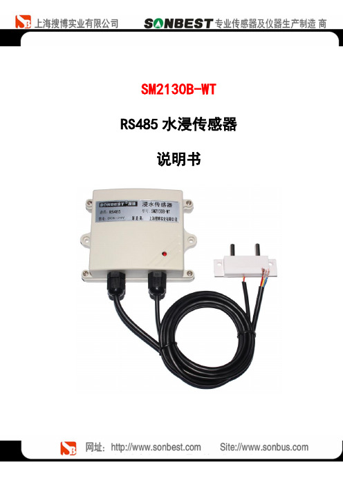
SM2130B-WT RS485水浸传感器说明书概述SM2130-WT漏水控制器是一款成本低廉的智能化液体泄漏检测设备,其输出信号包含继电器信号和 485信号。
不需要外加转换模块就可以轻松的与各种监控系统相整合,实现远程报警及远程设备的控制。
SM2130-WT漏水控制器可监控长达 200米的双芯漏液传感电缆。
它既可以和检测线缆安装使用,也可以和它其检测探头配套使用,一旦检测到液体,控制器立即启动继电器,输出常开常闭无源信号,可与其它集成采集主机联网使用。
该产品采用标准的 modbus-RTU 通信,方便与监控系统集成。
适用于检测机房基站、仓库、图书馆、博物馆和工业现场等重要场所的实时泄漏检测,更加可用于空气处理装置、冷冻机组、液体容器、泵槽等需要监测泄漏的设备。
特点与特色1. 敏感度高2. RS485 远距离通信接口,最远可达 1.2 公里3. 指令简单4. 6-24V 宽电源供电5. 高性价比技术参数及特点使用说明1.接线直接使用设备自带的引线,根据颜色提示进行接线2.安装尺寸3. 通讯协议设备所有操作或回复命令都为16进制数据。
默认通讯波特率:9600,8,n,1。
基本命令格式:[设备地址][功能码][起始地址:2字节][数据长度:2字节][CRC16校验]意义如下:A、设备地址:设备地址范围为1-249,其中250即0xFA为通用查询地址,当不知道设备地址时,可用此通用查询地址进行查询。
B、功能码:不同的应用需求功能码不同,比如3为查询输入寄存器数据。
C、起始地址:查询或操作寄存器起始地址。
D、数据长度:读取的长度。
E、CRC校验:CRC16校验,低位在前,高位在后。
1)读取数据(功能码为0x03 )[设备地址][03][起始地址:2字节][数据长度:2字节][CRC16校验]设备响应:[设备地址][命令号][返回的字节个数][数据1][CRC16校验]响应数据意义如下:A、返回的字节个数:表示数据的字节个数,也就是数据1,2...n中的n的值。
雨量传感器产品说明书

雨量传感器产品说明书 雨量传感器产品说明书雨量传感器产品说明书目录第1章产品简介 (4)1.1产品概述 (4)1.2功能特点 (4)1.3产品优势 (4)1.4主要参数 (5)第2章硬件连接 (6)2.1设备安装前检查 (6)2.2产品外观尺寸和内部结构 (6)2.2.1外观尺寸 (6)2.2.2内部结构 (7)2.2.3接口说明 (8)2.2.4安装说明 (9)2.2.5注意事项 (10)第3章配置软件安装和使用 (10)3.1传感器接入电脑 (10)3.2传感器监控软件使用 (11)雨量传感器产品说明书 3.3修改波特率和设备地址 (12)第4章通信协议 (12)4.1通讯基本参数 (12)4.2数据帧格式定义 (12)4.3寄存器地址 (13)4.4通讯协议示例以及解释 (14)4.4.1读取设备地址0x01的当前累加雨量值 (14)4.4.2设备地址0x01雨量清除指令 (14)第5章售后 (15)5.1联系方式 (15)5.2质保与售后 (15)5.3免责声明 (16)雨量传感器产品说明书 第1章产品简介1.1产品概述ZZ-RS-ABSB系列雨量传感器,是一款能够自动观测并存储“雨量”参数的仪器,分为ABS材质和不锈钢材质两种。
我司研发的传感器外型小巧轻便,便于携带和组装,用于测量自然界降雨量,同时将降雨量转换为以开关量形式表示的数字信息量输出,以满足信息传输、处理、记录和显示等的需要。
广泛适用于气象台(站)、水文站、农林、国防、野外测报站等有关部门,可为防洪、供水调度、电站水库水情管理提供原始数据。
1.2功能特点ZZ-RS-ABSB系列传感器,具有功耗低、灵敏度高、安装便利、操作简单、使用方便等特点,可长期在野外观测并记录雨量数据;同时还具备24小时数据自动清零、手动清零、历史数据记录等功能。
1.3产品优势(1)成本低,实用性极强,可长期在野外使用。
(2)体积小,操作简单,性能可靠。
WSTM01说明书
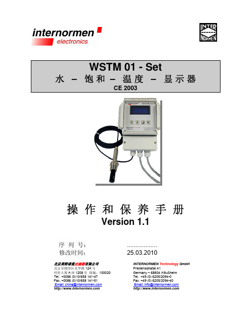
WSTM 01 - Set水 – 饱和 – 温度 – 显示器CE 2003操 作 和 保 养 手 册Version 1.1序 列 号: 修改时间:北京英特诺曼过滤器有限公司北京市朝阳区光华路 12A 号 科伦大厦 A 座 1208 室 邮编:100020 Tel. +0086 (0)10/658 141-47 Fax. +0086 (0)10/658 141-51 Email: china@ .................. 25.03.2010INTERNORMEN Technology GmbH Friedensstraße 41 Germany – 68804 Altlußheim Tel. +49 (0) 6205/2094-0 Fax. +49 (0) 6205/2094-40 Email: info@ 目 录1.1.1 1.2页3安全说明不正确操作导致的危险………………………………………………………………….. 3 依照规定进行使用……………………………………………………………………….. 32.2.1 2.2首次运行4构造……………………………………………………………………………………….. 4 完成运转前的准备……………………………………………………………………….. 43.油饱和度的检测63.1 水在液压油中造成的影响……………………………………………………………….. 6 3.2 检测原理………………………………………………………………………………….. 6 3.3 检测过程………………………………………………………………………………….. 7 3.4 对 WSTM 01 中软件的操作…………………………………………………………….. 7 3.4.1 操作键………………………………………………………………………………… 7 3.4.2 菜单结构……………………………………………………………………………… 8 3.4.3 主菜单………………………………………………………………………………… 9 3.4.3.1 步骤……………………………………………………………………………….. 9 3.4.3.1.1 设置存储时间间隔…………………………………………………………… 9 3.4.3.1.2 选择油的型号………………………………………………………………...10 3.4.3.1.3 开始…………………………………………………………………………...10 3.4.3.2 数据管理………………………………………………………………………… 11 3.4.3.2.1 数据传输…………………………………………………………………….. 11 3.4.3.2.2 数据删除…………………………………………………………………….. 12 3.4.3.2.3 数据存储…………………………………………………………………….. 12 3.4.3.3 设置……………………………………………………………………………… 12 3.4.3.3.1 极限值的设置……………………………………………………………….. 13 3.4.3.3.2 时间的设置………………………………………………………………….. 13 3.4.3.3.3 温度格式的设置…………………………………………………………….. 14 3.4.3.3.4 标准值的设置……………………………………………………………….. 14 3.5 检测结果的分析利用…………………………………………………………………… 15 3.5.1 用%形式来显示饱和度...……………………………………………………………15 3.5.2 用 ppm 形式来显示水的含量……………………………………………………….16 3.6 数据传输和数据管理…………………………………………………………………… 174.4.1WSTM 01 的保养 WSTM 01- Set 标准值的设定19 18传感器的清洁…………………………………………………………………………… 195.5.1 5.2WSPS 03 -传感器……………………………………………………………………… 19 温度探测器的安装……………………………………………………………………… 196.6.1 6.2 6.2.1 6.2.2 6.3 6.4附录20技术数据………………………………………………………………………………… 20 连接说明.............................................................................................................. 21 WSPS 03 – 湿度传感器…………………………………………………………… 21 WSTM 01 – 显示装置……………………………………………………………… 22 适用范围—兼容性................................................................................................ 24 触点负载............................................................................................................... 247.排除故障2521.1.1安全说明不正确操作导致的危险WSTM 01 – Set 通过 IEC 1010-1/ EN 61010 – 1, Teil 1 标准的安全测试和验收,有着 电子和液压一体化的保护装置,能为在规定的使用范围内提供安全运行的保障。
Series TTW 天气抗渗浸湿温度传感器传输器规格与安装和运行说明书

Series TTW Weatherproof Immersion Temperature TransmitterSpecifications - Installation and Operating InstructionsBulletin TE-TTWTheSeries TTW Weatherproof Immersion Temperature Transmitter combines three popular products into a single package. Our TBU series head mountedtemperature transmitter is factory mounted into our A-709 enclosure. A Pt100RTD version of our TE series is wired to the transmitter, giving insertion lengths up to 18”. Each transmitter is factory programmed and calibrated to output a 4 to 20 mA signal proportional to the 32 to 212°F (0 to 100°C) temperature range.OPERATIONThe sensor offset can be adjusted through the software. The USB cable may be connected to the transmitter without causing any measurement errors.The user must select the sensor and most suitable range to the process. The chosen range must not exceed the maximum range specified for that sensor and should not be narrower than the minimum range for that same sensor.It is important to note that the transmitter accuracy is based on the maximum range of the sensor used, even when a narrower range is programmed.Note: When Pt100 simulators are used with the transmitter, make sure the excitation current is compatible with the Pt100 excitation current of the transmitter, which is 0.8 mA.®Printed in U.S.A. 8/18FR# 444484-00©Copyright 2018 Dwyer Instruments, Inc.CONFIGURATIONThe factory configuration for the transmitter is sensor Pt100 with a 2-wire set up and a range of 0 to 100°C with upscale error condition. If this configuration fits the system requirement, no further action is required and the transmitter is ready to be installed. Changes to the configuration are possible through the software. The 2-wire configuration of the Pt200 sensor is shown below in Figure 1.INSTALLATION KEYNOTESSection of the cable used: 0.14 to 1.5 mm 2.Recommended torque in the terminal: 0.8 Nm. SAFETY INFORMATIONAny control system design should take into account that any part of the system has thepotential to fail. This product is not a protection or safety device and its alarms are not intended to protect against product failures. Independent safety devices should always be provided if personnel or property are at risk.Product performance and specifications may be affected by its environment and installation. Its user’s responsibility to assure proper grounding, shielding, cable routing and electrical noise filtering, in accordance with local regulations, EMC standards and good installation practices.MAINTENANCE/REPAIRUpon final installation of the Series TTW, no routine maintenance is required. The Series TTW is not field serviceable and is not possible to repair the unit. Field repair should not be attempted and may void warranty.WARRANTY/RETURNRefer to “Terms and Conditions of Sale” in our catalog and on our website. Contact customer service to receive a Return Goods Authorization number before shipping the product back for repair. Be sure to include a brief description of the problem plus any additional application notes.CONFIGURATIONDuring the setup, the transmitter is powered by the USB, not requiring an external power supply.The transmitter setup can also be made by connecting it to the loop using the loop power supply. There is no electrical insulation between the transmitter and the communication port (interface), therefore it is not recommended to configure it with the sensor inlet connected to the process. See Figure 2 for the USB cable connectionswhen it is loop powered.Figure 1Figure 2Sensor signals conductors must go through the plant system separate from power leads (loop), if possible in grounded conduits.It is recommended to use suppressors in contact coils, solenoids and any inductive load.The instruments must be powered from the instrumentation power supply circuit.In control and monitoring applications, it is essential to consider what can happen when any part of the system fails.The USB connection port (interface) is not electrically isolatedfrom the transmitter’s input.TO PC USB PORTPT100 SENSORLOAD。
- 1、下载文档前请自行甄别文档内容的完整性,平台不提供额外的编辑、内容补充、找答案等附加服务。
- 2、"仅部分预览"的文档,不可在线预览部分如存在完整性等问题,可反馈申请退款(可完整预览的文档不适用该条件!)。
- 3、如文档侵犯您的权益,请联系客服反馈,我们会尽快为您处理(人工客服工作时间:9:00-18:30)。
应用范围
适用于机房、空调房等场所的漏水检测。
主要技术参数
外形结构
图 1
信号变换器接线图
图 2
1、2接线端为电源输入,1为正,2为负。
4、5接线端为继电器输出,漏水告警时继电器输出短路,同时灯变为红色。
6、7接线端外接漏水感应绳。
漏水感应绳接入时没有方向性,可以增加延长线。
安装方式
图 3
传感器感应绳安装在容易产生漏水的地方。
把信号变换器安装在感应绳附近,用两芯线连接感应绳和信号变换器。
信号变换器用DIN35MM标准导轨槽安装。
连接好电源和输出线后,一加电信号变换器处于正常检测漏水的工作状态,灯为绿色,闪烁,输出为开路;当有漏水发生时,产生告警,灯由绿色变化为红色,闪烁,输出为短路;漏水消失后,告警恢复为正常的工作状态,灯由红色变化为绿色,闪烁,输出为开路;
注意事项
传感器应该安装在最能代表被测环境状态的地方,避免安装在位置比较高的死角、或者远离空调、水管接头的场所。
联系方式
QQ:380942543 ; E-mail:Arvin.wu@。