WDT-W大吨位说明书
WD 产品说明书 V2.0
北京鸿远鹏奥科技有限公司二、北京鸿远鹏奥科技有限公司公司总机:+86-010-******** 传真:+86-010-********销售热线:+86-010-********电子邮件:*******************公司网址:公司地址:北京市海淀区西三旗金燕龙大厦 邮政编码:100096WD 产品用户手册Version 2.0本手册指所有权由北京鸿远鹏奥科技有限公司独家拥有。
未经本公司之书面许可,任何单位和个人无权以任何形式复制、传播和转载本手册之任何部分,否则一切后果由违者自负。
注意:本手册仅为WD 系列配置手册,本公司拥有对本手册的最终解释权,并保留对其描述的产品改进的权利。
WD-400 温度监测表主要特点:l测温范围-55℃~+125℃l温度分辨率0.0625℃l可设置上限/下限报警l具有RS485通讯接口l4位LED显示l10-40Vdc宽供电范围WD400温度监测表具有温度采集、显示、报警、控制、通讯功能于一体,仪表采用TDC数字温度传感(DS 18B2 0),测温精度:±0 .5℃,温度监测范围:-55℃~+125℃,温度分辨率:12位(0.0625℃)。
显示功能:WD400温度监测表采用4位红色LED数码管,用于显示温度数值,两个状态指示灯用于指示报警和通信状态。
报警和控制功能:WD400可设定报警温度点,一个继电器的无源接点输出,可用于报警指示或控制外部设备,如排风扇、加热器等设备,实现温度控制功能。
通信功能:WD400温度监测表配有标准的RS485总线接口,单一总线上可连接128台WD400仪表,每台WD400仪表具有独立的8位地址,该地址号可通过仪表面板上的按钮设定。
隔离性能:WD400具有高电气隔离性能,保证了仪表安全稳定的工作。
温度传感器、通信接口和供电电源之间具有电气隔离,这一性能,保证了仪表即使在恶烈的强电磁场干扰环境下,也能可靠工作。
宽供电范围:采用10-40Vdc的供电设计,可以对温度监测表进行远距离供电,而不受线路压降的影响,单一电源即可对分布现场的仪表供电,适合分散点的温度监测。
国际货运代理专业术语解释

Rhine-Main-Danube System rate not reported routing order Remaining on board Refer to our telex receipt of goods Roll-on/roll-off round charter party rate to be arranged
(Institute
Cargo 基本险,水渍险,承保单 独海损(英国保险协会货 物险条款)
Way- bill will be done whether cleared customs or not
运单 将完成 清关与否
working day (s) width
工作日 宽(度)
with effect from Whether in free pratique or not Working Group weight
有关
Recapitulation
概括
Reduced
降低
Redelivery
交还
reference
参考
representative
代表
rent-a-container
租一个集装箱
restrict(ed)
限制,受限制的
returned or retired
返回的或退休的
Regards
问候
reinsurance
T ton the air cargo tariff (IATA) through bill of lading to be named (ship) time charter traffic conference area (IATA)
Time charter on trip basis time of departure Twenty foot equivalent unit (containers) Through International transit by rail Taking inward pilot Customs Convention on the international transport of goods under
称重产品手册

《称重管理系统》(Win XP/2000/2003版)使用说明书目录一、准备工作 (3)二、快速入门 (3)三、基础知识 (4)四、操作指南 (7)称重管理 (7)称重记录 (10)报表打印 (13)配置 (14)预置词组 (16)仪表通讯 (17)磅单管理 (17)用户管理 (18)系统初始化 (18)备份与还原 (19)五、问题解答 (19)“” (19) (20)六、称重软件的其他应用 (21)第一节准备工作1.连接称重显示仪表和电脑。
2.插入光盘,安装《称重管理系统》。
3.插入加密狗(无需安装驱动)。
4.运行《称重管理系统》。
5.设置“仪表通讯”。
设置方法:先点击“称重管理”,再点击“配置”菜单下的“仪表通讯”。
根据您当前所使用的仪表选择仪表类型,设置串口参数。
设置正确后按“确定”。
如果设置正确,此时称重界面上的重量显示屏上的数字会和仪表上的重量保持一致。
否则重量显示屏上会显示”8888.88”。
6 . 以系统管理员身份进入系统登陆“系统配置”—“用户管理”设置操作员帐号、密码和权限(详见“”功能说明)。
7 . 系统设置完成后,在正式启用前删除数据库中的测试数据。
具体流程:登陆系统—“系统配置”—“初始化数据”—选择“完全清楚”或“条件清除”。
第二节快速入门●假定《称重管理系统》已经按照出厂设定值已正确安装完毕,整个系统已能正常工作。
操作步骤1.打开电脑:打开电源,启动Windows操作系统。
2.运行系统:用鼠标双击桌面上的“称重管理系统”。
3.核对身份:登录对话框出现后,选择操作员,输入密码后按回车,或者点击”登录”按钮。
(注:起始密码为空。
)4.称取重量:等汽车在秤台停稳后,如果是空车则单击“称皮重”;如果装了货物则单击“称毛重”。
然后单击“车牌号”旁的空白处,输入车牌号。
注意车牌号一定要输正确,因为系统根据车号自动查找并匹配汽车的毛重与皮重,并据此计算出净重。
此时也可输入其它信息:如货物名称,规格等。
西部全球静态罐子产品说明书

250, 500, 1000, 1800FCPContentsINTRODUCTION (1)DESCRIPTION (2)SIGN-OFF FORM (3)IDENTIFICATION MARKS (4)UNIT SPECIFICATION (6)SAFETY (7)ACCESS AND SECURITY (11)CABINET OVERVIEW (12)CENTRE OF GRAVITY (13)LIFTING & HANDLING (17)FILLING THE FCP (18)DISPENSING FUEL (19)TRANSPORTING (19)STRAPPING CHARTS (20)MAINTENANCE AND SERVICE SCHEDULE (24)RECOMENDED INSPECTION / MAINTENANCE (25)INNER TANK REMOVAL (26)TORQUE SETTINGS (28)ENVIRONMENTAL RESPONSIBILITY (29)TROUBLE-SHOOTING (30)WARRANTY (31)INTRODUCTIONThank you for choosing Western GlobalPlease read the contents of this manual before use. •Ensure all operators are fully conversant with the procedures for lifting, loading, positioning, filling, maintaining and use of the unit•By understanding and following the information and procedures in this manual, your tank will give you many years of safe use•Certain information in this manual is governed by law and is subject to change without prior notice. Great care has been taken to ensure that the information is correct at the time of publication.•However, it is the owner’s / user’s sole responsibility to ensure that they and the tank fully comply with all legal requirements. Western Global cannot and will not accept any liability for any inaccuracy or incorrectly stated legal requirements•Western Global reserves the right to alter product specifications without prior notice or obligationWestern Global Tanks are design approved under various Global / International / National / Regional standards of safety11DESCRIPTIONFCP – Static Fuel Tank•The FCP range of fuel tanks have been designed to enable safe storage of Flammable & Combustible fluids•The FCP can be used as an auxiliary fuel tank, feeding generators etc., and for refuelling other equipment via a dedicated fuel pump•All pipe work and pump systems are stored beneath a secure, lockable access lid•The FCP must be empty before transporting•To aid both transporting and handling, the FCP is fitted with forklift pockets (Lift empty only)•Containment capacity equal to 110% of the primary tank’s capacity•The design enables maintenance of the containment area without specialty equipment•The FCP has a comprehensive range of connection points to enable attachment of various fittings•The FCP can supply fuel to multiple feed lines•The FCP can be used to refuel independent equipment•The FCP is approved to UL142 Standard for Steel Aboveground Tanks for Flammable and Combustible LiquidsSIGN-OFF FORM•The equipment provider should follow the general Safety Standards•Anyone who will be using and/or maintaining the tank must read and clearly understand ALL Safety, Usage and Maintenance information inthis manual•Periodic reviews of SAFETY and OPERATION should be standard practice for all your equipment• A sign-off sheet is provided for your records, showing all personnel working with the equipmentI have read and understand the information in the Operator’s Manualand have been instructed in the operation of the equipmentDate Employee Signature Employer SignatureIDENTIFICATION MARKSEach tank is supplied with 3 unique identification numbers.1.Western Serial Number2.Manufacturing Serial Number3.UL/ULC Serial Number Array1, Western SerialNumberThe UN IBC Plate is located on the external of the tank (front or Side near thecabinet area2, ManufacturingSerial Number Tank number is positioned in the cab area and will be permanently attached tothe main tank.3, UL/ULC SerialNumberThe UL Plate is located on the external of the tank (front or Side near the cabinetareaRecord your serial numbers hereWestern Data-plate Serial NumberManufacturing Serial NumberUL/ULC Data plate Serial NumberPlant Number**Optional customer plant numberUNIT SPECIFICATION Capacities / DimensionsModelCapacityLitres US Gallon Imp. Gallon Nominal 95% Nominal 95% Nominal 95%FCP250 921 875 243 231 203 192 FCP500 2000 1900 528 502 440 418 FCP1000 3846 3654 1016 965 846 804 FCP1800 7048 6696 1862 1769 1550 1472ModelWeightKG LBS TARE GROSS TARE GROSSFCP250 420 1295 926 2855 FCP500 681 2581 1501 5690 FCP1000 1252 4906 2760 10816 FCP1800 1983 8679 4372 19134ModelDimensionMetric (mm) Imperial (Inch)L W H L W HFCP250 1142 1142 1294 45 45 51 FCP500 2190 1132 1294 86 45 51 FCP1000 2298 2198 1172 90 87 46 FCP1800 3947 2190 1172 155 86 46SAFETYBefore using this equipment and to avoid personal injury, carefully read and understand these instructions.General•If there is anything you do not understand, contact your supplier for advice •The unit must be operated by authorised personnel only•This unit must not be moved, filled, maintained or operated by persons who are under the influence of alcohol or drugs, tired or unwell•You MUST perform a risk assessment before using this equipment to ensure your safety and the safety of others•Wear the correct Personal Protective Equipment for the task you are performing•Do not wear loose jewellery or clothing that may get in the way or become trapped in the mechanism•Inspect the unit before use, if there is any doubt about its condition, DO NOT USE IT•Do not smoke – No naked flames near tank•Please follow all necessary Transportation of Dangerous Goods act, regulations and codes, National and Regional Fire Safety Codes, and otherInstallation Codes as applicable in your region / country of use.No Smoking No Open Flames Authorised Access OnlyWear Safety Glasses Wear Safety Helmet Wear Ear ProtectionWear Safety Shoes Wear Safety Gloves Wear CoverallsNOTE: Please check with the local authority for any further siterequirements or regional legislation. A full risk assessment may berequiredLimitations of use•The FCP is designed for the safe storage of noncorrosive, stable flammable and combustible liquids that have a specific gravity not exceeding 1.0 inaboveground applications•UL 142 Listed tanks are intended for installation in accordance with a variety of installation codes, including NFPA 30, NFPA 30A, NFPA 31, NFPA37, NFPA 1 and the International Fire Code.•The FCP is not suitable for use undergroundSafe practiceThe storage, transportation and dispensing of Flammable & Combustible fluids is governed by law and it is the user/operator who has sole responsibility to ensure that any such rules and regulations are abided by.Earthing point•The unit is fitted with an earthing point. This can be found on bottom frame of the unit•Used to protect against static electricity build up, this should be connected toa suitable earthing point, by a qualified electrician, when in use Array1.Earth pointExampleVentingEach unit has 2 common vents installed; these are in the Cab Area of the tank. IMPORTANT: Do not operate the unit if these vents are damaged ormissing•2” Pressure Vacuum Vent – Allows movement of air into the unit at low pressure during the pumping process and allows air out of the unit at a higher pressure to stop an over pressure of the internal tank•¼” Roll over Vent – Allows free flow air into and out of the tank at all times, this low volume vent will fully close if the tank is inverted or turned on its side •For static installation follow local regional, state and national Fire Safety Codes and other governing Installation Codes for the Normal and Emergency Venting equipment and appurtenances.1.2” Pressure / Vacuum Vent2.¼” Roll Over Vent3.The FCP1800 has an additionalemergency vent portpostionoed to the rear of theunitACCESS AND SECURITYAccess to the Cab Area•The cabinet hatch is constructed of a heavy-duty steel, care should be taken when opening or closing•The cabinet hatch should be kept closed when the FCP is not being used to protect the fittings and containment area from weather conditions. Access to Containment•The inner tank can be removed from the containment to allow easy inspectionSecurity•The FCP is fitted with a range of connections to enable the supply of Flammable & Combustible fluids. All the connections are housed behind thecabinet hatch, which can be locked using a suitable security padlockCABINET OVERVIEWStandard Unit1.1” Feed2.3” Fill Point3.2” Pressure / Vacuum Vent4. 2 x 1.5” Spare Ports5.Emergency 2” Vent Ports6.¼” Roll Over Vent7.Dip Stick8.Lid ClipFor the FCP1800 item 5 is replaced with a 6” emergency vent portCENTRE OF GRAVITYFCP250 Centre of Gravity2Center Of GravityX (mm) Y (mm) Z (mm) Empty 569 539 598Full 570 562 599Centre Of GravityX (mm) Y (mm) Z (mm) Empty 572 1035 580 Full 572 1076 612Centre Of GravityX (mm) Y (mm) Z (mm) Empty 1100 1088 469 Full 1099 1134 540Centre Of GravityX (mm) Y (mm) Z (mm) Empty 1046 1918 452 Full 1046 1966 541LIFTING & HANDLINGIMPORTANT: Always prepare a Lifting Plan/Risk Assessment. By Forklift / Tele-handler•Each FCP is fitted with forklift pockets which are designed to allow the FCP to be raised by a forklift/tele-handler. The FCP can be lifted from all 4 sides. This must be considered in your risk assessment•It is important that the total gross weight of the FCP is not more than half (50%) of the forklift’s maximum SWL. Ensure that the forklift’s forks are set to the correct width for the FCP’s fork pockets1. Fork PocketsWARNINGDo not allow anyone under the raised load at any time or for anyreason.PositioningWhere the FCP is to be permanently positioned for use (long or short term) it is important that certain aspects are considered•You should make sure that both supplying vehicle and receiving vehicle have safe and easy access to the FCP•The position should be selected where the unit will be protected from accidental impact•Consideration should be given to the location of overhead services such as telecommunications, power cables and overhanging obstructions. Be awareof the location of underground services, such as drains, and manhole covers •You must also consider the ground surface and make sure it can support the weight of the FCP, its contents when full and any stored equipment such aspumps, without the risk of subsidence. It should be positioned on smooth and level ground with access available to the rear and sides •Allow for access that may be required by the emergency services should it become necessaryFILLING THE FCP•DO NOT FILL TANK WHEN DISPENSING IS IN OPERATION•Only fill the FCP to 95% of its nominal capacity See UNIT SPECIFICATION•Filling should only be performed by a suitably trained person and only following a full risk assessment•The FCP must be positioned on a firm level surface.•Before filling, ensure that you have a suitable spill containment kit and that you are wearing all required PPE•Nozzle Fill - Unlock and open the access lid. Unscrew and remove the 3” filler cap, place the filling nozzle in the 3” port•Do not leave the nozzle unattended during the filling process•Observe the fuel level for an indication of tank capacity, then once filled, replace the filler cap and clean up any spillsDISPENSING FUELThere are two options available for dispensing/supplying fuel. Either manually via a fuel pump and nozzle or by direct coupling to the equipment such as a generator. •By Fuel Pump - For the information about any pump system fitted to this FCP, please refer to documents supplied with the pump.•Direct Coupling - enables continuous fuel feed to equipment such as generators where fuel is required continuously. TRANSPORTINGNOTE: TRANSPORT EMPTY ONLY•In transport ALL ports, valves and vents must be closed•Ensure pump is turned off•Close and lock the access lid•The FCP must be secured firmly to its means of transport•The FCP is designed with the structural strength to allow stacking 2 high when empty.•Always mate the corner brackets together to stabilise the stack.•Use only a hoist or forklift with the required lift capacity to raise, lower or stack the tanks.STACKING•The FCP is designed with the structural strength to allow stacking 2 high when full and 3 high when empty.•Always mate the corner brackets together to stabilise the stack.•Use only a hoist or forklift with the required lift capacity to raise, lower or stack the tanks. ArrayStacking ArrangementSTRAPPING CHARTS FCP250Depth (cm) Depth (in) Fuel Level(Litre) Fuel Level(US-Gallon)Fuel Level(Imp Gallon)2 0.8 20 5 46 2.4 60 16 1310 3.9 100 27 2214 5.5 140 37 3118 7.1 180 48 4022 8.7 220 58 4926 10.2 261 69 5730 11.8 301 79 6634 13.4 341 90 7538 15.0 381 101 8442 16.5 421 111 9346 18.1 461 122 10150 19.7 501 132 11054 21.3 541 143 11958 22.8 580 153 12862 24.4 617 163 13666 26.0 654 173 14470 27.6 689 182 15274 29.1 724 191 15978 30.7 757 200 16782 32.3 789 208 17486 33.9 820 217 18090 35.4 850 225 18795 37.4 878 232 19398 38.6 906 239 199100 39.4 919 243 2021.Highlighted on the strapping chart is the maximum safe fill level @ 95% of thenominal volume. DO NOT FILL ABOVE THIS LEVEL2.The dip chart volume is taken from the lowest point in the tank.3.When programming a level monitoring system, the difference in floor heightat the port location (where the instrument is mounted) should be subtracted from the fill height for each volume increment line to equate tocorresponding fill height at the instrument location.Depth (cm) Depth (in) Fuel Level(Litre) Fuel Level(US-Gallon)Fuel Level(Imp Gallon)2 0.79 41 11 96 2.36 123 33 2710 3.94 206 54 4514 5.51 288 76 6318 7.09 370 98 8222 8.66 453 120 10026 10.24 535 141 11830 11.81 617 163 13634 13.39 700 185 15438 14.96 782 207 17242 16.54 864 228 19046 18.11 946 250 20850 19.69 1029 272 22654 21.26 1111 293 24458 22.83 1192 315 26262 24.41 1272 336 28066 25.98 1351 357 29770 27.56 1429 377 31474 29.13 1505 398 33178 30.71 1581 418 3488232.28165543736486 33.86 1728 457 38090 35.43 1800 476 39694 37.01 1871 494 41295 37.40 1906 504 419100 39.37 1975 522 4351.Highlighted on the strapping chart is the maximum safe fill level @ 95% of thenominal volume. DO NOT FILL ABOVE THIS LEVEL2.The dip chart volume is taken from the lowest point in the tank.3.When programming a level monitoring system, the difference in floor heightat the port location (where the instrument is mounted) should be subtracted from the fill height for each volume increment line to equate tocorresponding fill height at the instrument location.Depth (cm) Depth (in) Fuel Level(Litre) Fuel Level(US-Gallon)Fuel Level(Imp Gallon)20.798823196 2.36263695810 3.944381169614 5.51613162135187.09788208173228.669632542122610.2411383012503011.8113133472893413.3914883933273814.9616634393664216.5418374854044618.1120105314425019.6921805764805421.2623486205175822.8325146645536224.4126787075896625.9828397506247027.5629987926597429.1331548336947830.7133098747288232.2834619147618633.8636119547949035.4337589938271.Highlighted on the strapping chart is the maximum safe fill level @ 95% of thenominal volume. DO NOT FILL ABOVE THIS LEVEL2.The dip chart volume is taken from the lowest point in the tank.3.When programming a level monitoring system, the difference in floor heightat the port location (where the instrument is mounted) should be subtracted from the fill height for each volume increment line to equate tocorresponding fill height at the instrument location.Depth (mm)Depth (In)Fuel Level(Litre)Fuel Level(US Gallon)Fuel Level(Imp Gallon)2 0.79 156.0 41.2 34.36 2.36 469.0 123.9 27.210 3.94 782.0 54.4 45.314 5.51 1095.0 289.3 240.918 7.09 1408.0 372.0 309.722 8.66 1721.0 454.6 378.626 10.24 2034.0 537.3 447.430 11.81 2347.0 163.1 516.334 13.39 2660.0 702.7 585.138 14.96 2973.0 785.4 654.042 16.54 3285.0 867.8 722.646 18.11 3596.0 950.0 791.050 19.69 3904.0 1031.3 858.854 21.26 4209.0 1111.9 925.858 22.83 4513.0 1192.2 992.762 24.41 4814.0 1271.7 1058.966 25.98 5112.0 1350.4 1124.570 27.56 5409.0 1428.9 1189.874 29.13 5703.0 1506.6 1254.578 30.71 5995.0 1583.7 1318.78232.286285.0437.11382.586 33.86 6572.0 1736.1 1445.687.7534.556696.01768.91472.990 35.43 6857.0 1811.4 1508.392.7 36.50 7048.0 1861.9 1550.34.Highlighted on the strapping chart is the (MSF) maximum safe fill level @ 95%of the nominal volume. DO NOT FILL ABOVE THIS LEVEL5.The dip chart volume is taken from the lowest point in the tank.6.When programming a level monitoring system, the difference in floor heightat the port location (where the instrument is mounted) should be subtracted from the fill height for each volume increment line to equate tocorresponding fill height at the instrument location.MAINTENANCE AND SERVICE SCHEDULE V = Visual inspection P = Physical Check L = Lubricate R = ReplaceItem Daily Weekly Monthly 6 Monthly Yearly Other Reference / CommentsGeneralHousekeeping V P Check site and tank. Remove debris etc.Firefightingmedia (if fitted) V PV = Check inplace andunusedP = Testpressure andfunctionDoors V L V = Visualinspection L = GreaseshingesSignage V/RCheck damageand wear TankBall valves P P = Check operationVents, fittingsand pipelines V P V = Visualchecks for leaks and damageP = physical check, bolt tightness, paint deteriorationInterstitialspace (Containment) PCheck for wateror productTank earthing V P V = Visual check OKP = Test continuityLevel gauges V P V = Visualchecks for leaks and damageP = Remove and check operationRECOMENDED INSPECTION / MAINTENANCE Western recommend that the owner of the FCP carries out regular inspection. This is for guidance only.IMPORTANT: Always follow local or preventive schedulesEvery 2 ½ years•External inspection•Function of all services equipment•Leak test.Every 5 years•Internal inspection•External inspection•Function of all services equipment•Leak test.Record KeepingIt is recommended that a report of each inspection and pressure test is kept for each tankBelow is a simple example of an inspection record sheetOwner Date of manufactureModelSerial Number Plant NumberCapacityDate 2.5 or5 Year Pass or Fail Comments InspectorsName SignatureINNER TANK REMOVALFor periodic inspection and maintenance, you may be required to remove the inner tank from the outer tank. Follow local Health and Safety rules when carrying out this operation.IMPORTANT - Ensure the tank is empty before lifting.1. Remove all 4 cornerbrackets. Store brackets, nuts and bolts safely2. Remove 2 x side and 2 xend rails. Store rails, nuts and bolts safely3. Insert 4 x M22 lifting eyesin each corner of the inner tank4. Using a 4-leg lifting chainattached to each corner carefully remove the inner tankTo re-install the inner tank into the containment, follow steps 1 – 4 inreverse. Always ensure the bolts are torqued.Typical Lifting Eye M22TORQUE SETTINGSNuts and BoltsIf the tank is required to be dismantled and re-assembled the tank nuts and bolts used are required to be torqued, torque settings are shown in the table below.Metric Torque SpecificationsSize Typical Maximum Tightening Torque Nm(lb ft)Property ClassGrade 8.8 Grade 10.9M8 30 (21) 40 (30)M10 55 (42) 75 (60)M12 100 (74) 135 (106)Torque figures indicated above are valid for lightly oiled threads. Therefore, do not grease or oil bolts or cap screws unless otherwise specified.Torque value for bolts and cap screws are identified by their head markings(property class).ENVIRONMENTAL RESPONSIBILITYCorrect and considerate management of Flammable & Combustible fluids, its storage and transfer are the responsibility of everyone who operates or maintains this equipment. All necessary precautions should be made to prevent spills and subsequent pollution of the environment.Have in place a clear action plan to deal with accidental spill, no matter how small or large. Ensure that you have a Flammable & Combustible fluids spill containment kit available and that you understand its correct use.SpillsShould a spill occur when emptying the containment, or when filling or transferring fuel, clear the spill as quickly as possible using absorbent material. Ideally, you should use a dedicated spill kit which will contain all the necessary items to retain and remove such a spill.•DO NOT hose the area down or use any detergents•DO NOT allow the fuel to enter drains or watercourses•Spills must be reported to your local Authority•All material used to retain and remove a spill should be bagged and collected by a registered carrierContainmentThe FCP containment area safeguards against any spill exiting the unit and polluting the immediate area. The containment is designed to retain up to 110% of the unit’s primary tank maximum storage capability.•Check regularly for liquid in the containment•Remove any water•Take immediate remedial action if product or water is foundWARNINGWaste may only be collected by a registered carrier.DisposalWhen maintaining, servicing or disposing of the FCP or consumable components, do not dispose of contaminated parts within general refuse.Refer to local authority regulations for their correct disposal.TROUBLE-SHOOTINGThe Transcube is a simple and reliable system Below we have listed common problems, causes and solutions that you may encounter. If a problem is difficult to solve, even after having read through this trouble-shooting section, please call your local Western Global distributor or dealer. Before you call, please have the tanks Identification Marks ready (Serial and Tank numbers) PROBLEMCAUSE SOLUTION Pump will not run No PowerConnect power wires to correct power source Pump Off Turn pump on Fuel in containment Loose fitting Tighten fitting Leaking CouplerReplace coupler Over fillingWatch fuel gauge when filling. Do not fill past 95% of the nominal capacity Water in containmentLid left open to weather Keep lid closedWARRANTYThe Company undertakes to replace or repair, free of charge, any defect which the Company considers to be due to faulty workmanship or material within 36 months (or otherwise stated) of the sale date, except for:•Defects arising from neglect, misuse or unauthorised modifications. •Damage caused by abuse, misuse, dropping or other similar damage caused by or because of a failure to follow transportation, storage, loading oroperation instructions.•Alterations, additions or repairs carried out by persons other than the manufacturer or their recognised distributors.•Transportation or shipment costs to and from the manufacturer or their recognised agents, for repair or assessment against a warranty claim, on any product or component.•Materials and/or labour costs to renew, repair or replace components due to normal wear and tear.•Faults arising from the use of non-standard or additional parts, or any consequential damage or wear caused by the fitting or use of such parts.IMPORTANTWarranty may, at the sole discretion of the manufacturer, be voided if the scheduled service/inspections are not carried out in accordance with the logbook. The manufacturer and/or their recognised agents, directors, employees or insurers will not be held liable for consequential or other damages, losses or expenses in connection with, or by reason of, or due to the inability to use the product for any purpose.HQ - WESTERN GLOBAL LTDWestern HouseBroad Lane, YateBristol - BS37 7LDTel: +44 (0) 1454 227 277 ***************************CANADATel: +1 (204) 772 6525**********************USATel: +1 (203) 847 4300**********************.com。
WDT-01漏水传感器说明书
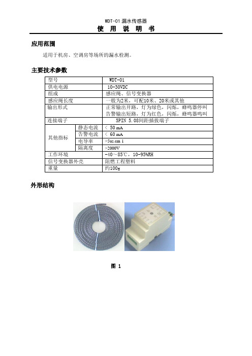
应用范围
适用于机房、空调房等场所的漏水检测。
主要技术参数
外形结构
图 1
信号变换器接线图
图 2
1、2接线端为电源输入,1为正,2为负。
4、5接线端为继电器输出,漏水告警时继电器输出短路,同时灯变为红色。
6、7接线端外接漏水感应绳。
漏水感应绳接入时没有方向性,可以增加延长线。
安装方式
图 3
传感器感应绳安装在容易产生漏水的地方。
把信号变换器安装在感应绳附近,用两芯线连接感应绳和信号变换器。
信号变换器用DIN35MM标准导轨槽安装。
连接好电源和输出线后,一加电信号变换器处于正常检测漏水的工作状态,灯为绿色,闪烁,输出为开路;当有漏水发生时,产生告警,灯由绿色变化为红色,闪烁,输出为短路;漏水消失后,告警恢复为正常的工作状态,灯由红色变化为绿色,闪烁,输出为开路;
注意事项
传感器应该安装在最能代表被测环境状态的地方,避免安装在位置比较高的死角、或者远离空调、水管接头的场所。
联系方式
QQ:380942543 ; E-mail:Arvin.wu@。
中联w450塔吊说明书

中联w450塔吊说明书中联W450塔吊是一种用于重型建筑施工的机械设备,本文将对其进行详细的说明,包括设备的特点、使用方法、注意事项等。
一、设备特点1.高效稳定:中联W450塔吊采用先进的液压系统和电气控制系统,具有卓越的工作性能和稳定性,能够高效地完成建筑施工任务。
2.广泛适用:该塔吊适用于不同的建筑工地,能够应对各种不同的工程要求和场地条件。
3.智能控制:中联W450塔吊采用智能化的控制系统,能够实现精确的载重和高效的操控,提高了工作效率和安全性。
4.载重能力强:该塔吊具有较大的载重能力,可满足需要搬运大型建筑材料的工地要求。
5.施工范围广:中联W450塔吊的起重高度和平衡臂长度较大,适用于高层建筑的施工,能够覆盖较大的施工范围。
二、使用方法1.设备操作:在使用前,需确保操作人员具备相关的操作培训,并严格按照操作手册中的步骤进行操作。
2.安全检查:每次使用前都需要对塔吊进行全面的安全检查,包括结构稳定性、起重绳索、电气系统等方面。
3.载重限制:严格按照设备的载重限制进行搬运操作,不得超载使用,以免引发安全事故。
4.工作环境:确保塔吊周围的工作环境整洁、平坦,杜绝掉落物品、堆积物等对安全的影响。
5.维护保养:按照设备的保养手册进行定期的维护保养工作,包括润滑、检查各部件的磨损状况等。
三、注意事项1.安全意识:使用塔吊时,操作人员必须时刻保持高度的安全意识,严禁酒后操作、疲劳驾驶等不安全行为。
2.风力限制:若遇到风力较大的天气,请停止使用塔吊,以免发生风吹塔倒的危险。
3.外部检查:在使用之前,必须对塔吊的外部环境进行全面检查,确保周围的建筑物、电缆线路等不会影响到塔吊的正常使用。
4.悬挂物预防:在起重过程中,应注意悬挂物与其他设备或人员的保持安全距离,以防止发生碰撞或伤害。
5.紧急情况处理:一旦发生紧急情况,应立即按照操作手册上的应急处理步骤进行处理,确保人员和设备的安全。
总结:中联W450塔吊是一种功能强大、稳定可靠的重型建筑设备,具有广泛的适用性和高效的工作性能。
w100说明书
设置参数
设置预设皮 重
系统参数:
5
第三章 相关系统参数说明
3.1 理论功能标定 1. 理论标定
执行此功能需设置的传感器参数:
:所使用的传感器的量程总和。
例如:如果使用 4 只量程是 1000kg 的传感器,那么这个参数应输入 4000.
:传感器灵敏度(默认值为 2.00000mV/V)
入键)
� 参数设定键(包含
、
、
、
.)
� 参数设定主要包含下列各项:零点标定、理论校秤、真实值校正、最小分度、 最大
秤量(量程)、 A/D 转换速率 、计量单位、模拟量输出。
� 调整校正方式:全自动数位校正 非线性:±0.01%(全量程)
第二章 外观功能与安装
2.1 接线图:
5 输出:可设置的设定值或者通过协议来进行远程输出管理。 3 输入:可设置的功能有:半自动清零,净重/皮重,极值,远程控制,打印。 注意:如果模拟量输出被选择,那么 3 输入、5 输出以及 E/EC 选择都不能再用。
本操作说明书以 W100 基本型为例介绍 LAUMAS 产品,其中包含详细的规格说明,安 装接线图,调整校正,功能设定以及操作方法等等。LAUMAS 产品可以满足您想要的任何一 种安装方式,盘面式安装您可以选择 W100、W200 或者 WDOS,轨道式安装小巧的 TLB 是 再适合不过的了。LAUMAS 称重变送器可以适用于不用的场合,例如 WDOS 可以用于最基本 的称重,还可用于配料秤、失重秤等等,WDESK 系列可用于汽车衡等等。为充分发挥指示 器的良好性能,请您在使用仪表之前,务必详细阅读本操作说明书。
1.4 数字处理规格
� 重量显示:6 位数 LED 字幕显示 字高 14mm � 显示解析度:300~30000 � 低于零点显示:负号(-)显示 � 过负载显示:″┄┄″ � 介面接口:1 个 RS-232 串行传输接口 � LED 指示灯: 净重、零点、 稳定、 单位 � 输入键:4 个输入键(包含归零、 皮重扣除 /皮重复归、 总重/净重转换 、功能输
32吨龙门吊说明书
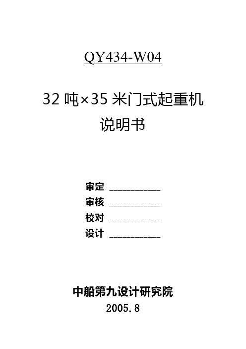
QY434-W0432吨×35米门式起重机说明书审定____________审核____________校对____________设计____________中船第九设计研究院2005.8目录页次目录---------------------------------------------------------- I 第一章性能和构造 1 1-1 概述--------------------------------------------------- 1 1-2 主要技术性能 1 1-3 主要金属结构 2 1-4 主要机构及设施 3 第二章起重机的建造 4 2-1 慨述---------------------------------------------------- 4 2-2 材料 5 2-3 金属结构的制造总则 6 2-4 焊接---------------------------------------------------- 7 2-5 金属结构件制造公差和要求----------------------- 8 2-6 司机室和起重小车的防雨要求-------------------- 10 2-7 机械制造---------------------------------------------- 10 2-8 润滑---------------------------------------------------- 12 2-9 除锈和油漆13 2-10 起重机轨道安装要求14 2-11 电气---------------------------------------------------- 14 第三章操作和整定------------------------------------------- 15 3-1 操作前的准备工作15 3-2 整定---------------------------------------------------- 15 第四章使用和维护164-1 安全使用注意事项16 4-2 定期检查---------------------------------------------- 16 4-3 润滑---------------------------------------------------- 17I第一章性能和构造本起重机是中储发展股份有限公司上海沪闵分公司委托第九设计研究院设计的门式起重机。
- 1、下载文档前请自行甄别文档内容的完整性,平台不提供额外的编辑、内容补充、找答案等附加服务。
- 2、"仅部分预览"的文档,不可在线预览部分如存在完整性等问题,可反馈申请退款(可完整预览的文档不适用该条件!)。
- 3、如文档侵犯您的权益,请联系客服反馈,我们会尽快为您处理(人工客服工作时间:9:00-18:30)。
目 录 安全事项_____________________________________________1
搬运注意事项_________________________________________2
安装的环境要求_______________________________________2
使用前须知___________________________________________3
使用注意事项_________________________________________3
维护保养注意事项_____________________________________4
常见故障及其排除方法_________________________________5
必需附件_____________________________________________6
◆ 手操盒简介____________________________________________6 客需附件_____________________________________________8
◆ 压缩试验夹具__________________________________________8 1. 压缩试验夹具______________________________________________8 2. 压缩夹具的安装____________________________________________8 3. 试样在压缩试验中的安装____________________________________9
◆ 弯曲试验夹具__________________________________________9 1. 弯曲试验夹具_____________________________________________9 2. 弯曲夹具的安装___________________________________________10 3. 试样在弯曲试验中的安装___________________________________10
◆ 锲型拉伸试验夹具_____________________________________11 1. 锲型拉伸夹具的组成部件___________________________________11 2. 锲型拉伸夹具_____________________________________________11 3. 锲型拉伸夹具的安装_______________________________________12 4. 试样在锲型拉伸中安装_____________________________________12 5. 大变形试验装置__________________________________________13 6. 大变形试验装置的安装_____________________________________14 7. 大变形试验装置的使用_____________________________________14
◆ 缝拉伸试验夹具______________________________________15 - 2 -1. 缝拉伸试验夹具的组成_____________________________________15 2. 缝拉伸试验夹具___________________________________________15 3. 缝拉伸试验夹具的安装_____________________________________16 4. 缝拉伸试验夹具中安装试样_________________________________16
◆ 环刚度试验夹具_______________________________________17 1. 环刚度试验夹具___________________________________________17 2. 环刚度试验夹具的安装_____________________________________17 3. 内径测量装置_____________________________________________17 4. 内径测量装置的安装_______________________________________18 5. 测头安装图______________________________________________18 6. 内径测量装置上钢丝的缠绕方法_____________________________18 7. 试样在环刚度试验中的安装_________________________________20
◆ 特殊夹具____________________________________________21 一章 概述__________________________________________22
◆ 用途和特点___________________________________________22 二章 技术规格、性能_______________________________23
◆ 技术规格___________________________________________23 ◆ 性能________________________________________________24 三章 试验机的结构__________________________________25
四章 软件手册______________________________________27
一. 系统要求___________________________________________27 1、PC计算机最低要求________________________________________27 2、操作系统________________________________________________27 二. 软件安装____________________________________________28
三. 软件卸载__________________________________________30 四. 软件使用__________________________________________31 1、主菜单__________________________________________________31 2、 各键功能_______________________________________________35 3、配置试验机—配置窗口___________________________________37
- 3 -● 测力传感器选项__________________________________________38 ● 变形选项________________________________________________38 ● 自动判断裂选项__________________________________________38 ● 自动返回选项____________________________________________39 ● 屈服后去掉引伸计________________________________________39 ● 定时间__________________________________________________39 ● 定负荷__________________________________________________39 ● 定变形__________________________________________________39 ● 预加载__________________________________________________39 4、数据处理—处理窗口______________________________________40 ① 单击输入键输入试验参数、环境参数及说明_________________41 ② 单击 备注 键进入备注输入表单___________________________42 ③ 单击自动计算键, 计算力学参数________________________42 ④ 单击出报告键,输出报告_________________________________43 ⑤ 计算器_________________________________________________46 ⑥ 废除、比较、标牌为保留键_______________________________46 ⑦ 曲线功能_______________________________________________46 5.自动力值校准和自动变形校准_______________________________49
五章 试验步骤______________________________________50
附图________________________________________________53
外观尺寸图______________________________________________53 防护外观图______________________________________________54 机器安装图______________________________________________55 操作人员位置____________________________________________56 工作空间________________________________________________57 警示位置图______________________________________________58 WDT-W 接线图____________________________________________59
- 4 -