S-RX28 -90DBM 2.4G无线影音接收模块解析及说明
HS-2850中文产品操作手册
HD/SD 12 通道便携式移动演播室
HS-2850
( 8 / 12 CHANNEL )
产品操作手册
目录
FCC 声明......................................................................................................................... 6 安装注意事项 .................................................................................................................. 6 产品保修 ......................................................................................................................... 7
ADH技术有限公司GP-1818MK GPS接收器模块说明书
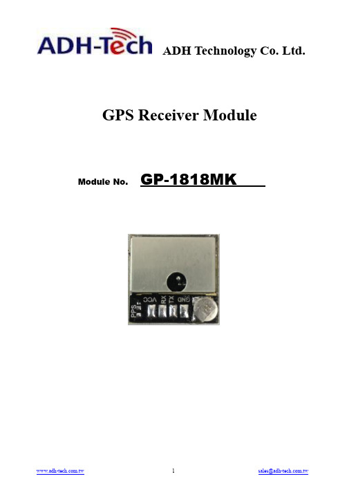
ADH Technology Co. Ltd.GPS Receiver Module Module No. GP-1818MK1. Product Information1.1 Product NameGP-1818MK1.2 Product DescriptionGP-1818MK is a GPS receiver build-in high performances -165dBm GPS chipset. GP-1818MK provides customer high position, velocity and time accuracy performances as well as high sensitivity and tracking capabilities. Customers benefit from the strength of both companies. Thanks to the low power consumption technology, the GPS receiver is ideal for many portable applications such as PDA, Tablet PC, smart phone etc.1.3 Product Features●Build on high performance GPS single chip MT3337●High Sensitivity -165 dBm●Lowpowerconsumption:************●Integrated LNA with low-gain mode for active antenna option●66 channels in Search mode and 33 channels "All-in-View" tracking●Up to 60,000 simultaneous search windows for fast TTFF and high sensitivity acquisitions ●Average cold start time under 29seconds(open sky)●Support standard NMEA-0183 protocol●Patch Antenna Size:18(w)mmX18(d)mmX7(h)mm●RoHS compliant (Lead-free)1.4 Product Application●Handheld GPS receiver application●Ideal for PDA, Pocket PC and other consumer devices requiring Positioning capability●Geographic Surveying●Sports and Recreation●Marine Navigation, Fleet Management●Automotive application●Car navigation and tracking●AVL and Location-Based ServicesTiming application1.5 Product Picture2. Technical Specifications2.1 General Characteristics2.1.1 GeneralFrequency L1, 1575.42 MHzC/A code 1.023 MHz chip rateAcquisition Channel66Tracking Channel332.1.2 AccuracyPosition 2.5m CEPVelocity0.1 m/s2.1.3 DatumWGS-84Default WGS842.1.4 Time To First Fix (TTFF)Hot start<1sec., averageWarm start<28sec., averageCold start<29sec., average2.1.5 SensitivityTracking Sensitivity-165dBm, typicalAcquisition Sensitivity-148dBm, typical for cold start2.1.6 Dynamic conditionAltitude18000m(Max)Velocity515m/s(Max)Acceleration 4gJerk 1g/s2.2 Electrical Characteristics2.2.1 DC PowerVoltage+3.3V-5V DCSupply current***********************2.2.2 Serial PortElectrical Interface Two full duplex serial communicationBaud rate9.6K(Default)Navigation update rate 1HzProtocol Message NMEA-0183 Ver 3.012.2.3 AntennaType Active patch antennaCenter Frequency1575.42 +/-1.032MHzPolarization RHCPImpedance 50 Ohm2.3 Environmental CharacteristicsOperating range-40°C ~ +85°CStorage range-40°C ~ +150°CRelative Humidity 5% ~ 80%2.4 Physical CharacteristicsLength18 mmWidth18 mmHeight7 mm2.5 Absolute Maximum RatingsParameter Min Typ Max UnitPower supply voltage-0.1 3.35V3. Software Interface3.1 NMEA V3.01 ProtocolIts output signal level is TTL: 9600bps (default), 8 bit data, 1 stop bit and no parity.It supports the following NMEA-0183Messages: GGA, GLL, GSA, GSV, RMC and VTG.NMEA Output Messages: the module board outputs the following messages as shown in Table.Table 1 NMEA-0183 Output MessagesNMEA Record DescriptionGGA Global positoning system fixed dataGLL Geogrphic position – latitude / longitudeGSA GNSS DOP and active satellitesGSV GNSS satellites in viewRMC Recommended minimum specific GNSS dataVTG Course over ground and ground speed3.1.1 GGA-Global Postioning System Fixed DataTable 2 contains the values of the following example:$GPGGA, 161229.487, 3723.2475, N, 12158.3416, W, 1, 07, 1.0, 9.0, M, , , ,0000*18Table 2GGA Data FormatName Example Units DescriptionMessage ID $GPGGA GGA protocol header UTC Position 161229.487 hhmmss.sss Latitude 3723.2475 ddmm.mmmmN/S Indicator N N=north or S=south Longitude 12158.3416 Dddmm.mmmmE/W Indicator W E=east or W=west Position Fix Indicator 1 See Table 2-1 Satellites Used 07 Range 0 to 12HDOP 1.0 Horizontal Dilution of PrecisionMSL Altitude 9.0 meters Units M meters Geoid Separation meters Units M metersAge of Diff. Corr. second Null fields when DGPS is not usedDiff. Ref. Station ID 0000Checksum *18<CR><LF>End of message terminationTable 2-1 Position Fix IndicatorValue Description0 Fix not available or invalid1 GPS SPS Mode,fix valid2 Differential GPS,SPS Mode,fix valid3 GPS PPS Mode,fix valid3.1.2 GLL-Geographic Position-Latitude/LongitudeTable 3 contains the values of the following Example:$GPGLL, 3723.2475, N, 12158.3416, W, 161229.487, A*2CTable 3 GLL Data FormatName Example Units Description Message ID $GPGGA GLL protocol header Latitude 3723.2475 ddmm.mmmmN/S Indicator N N=north or S=south Longitude 12158.3416 Dddmm.mmmmE/W Indicator W N=north or S=south UTC Position 161229.487 Hhmmss.ssStatus A A=data valid or V=data not validChecksum *2C<CR><LF>End of message termination3.1.3 GSA-GNSS DOP and Active SatallitesTable 4 contains the values of the following example:$GPGSA, A, 3, 07, 02, 26, 27, 09, 04, 15, , , , , , 1.8,1.0,1.5*33Table 4 GSA Data FormatName Example Units Description Message ID $GPGSA GSA protocol headerMode 1 A See Table 4-2Mode 2 3 See Table 4-1Satellite Used 07 Sv on Channel 1Satellite Used 02 Sv on Channel 2……Satellite Used Sv on Channel 12PDOP 1.8 Position Dilution of PrecisionHDOP 1.0 Horizontal Dilution of Precision VDOP 1.5 Vertical Dilution of PrecisionChecksum *33<CR><LF>End of message terminationTable 4-1 Mode 1Value Description1 Fix not available2 2D3 3DTable 4-2 Mode 2Value DescriptionM Manual-forced to operate in 2D or 3D modeA Automatic-allowed to automatically switch 2D/3D3.1.4 GSV-GNSS Satallites in ViewTable 5 contains the values of the following example:$GPGSV, 2, 1, 07, 07, 79, 048, 42, 02, 51, 062, 43, 26, 36, 256, 42, 27, 27,138, 42*71 $GPGSV, 2, 2, 07, 09, 23, 313, 42, 04, 19, 159, 41, 15, 12, 041, 42*41Table 5 GGA Data FormatName Example Units Description Message ID $GPGSV GSV protocol headerNumber ofMessages12 Range 1 to 3Messages Number1 1 Range 1 to 3Satellites in View 07Satellite ID 07 Channel 1 ( Range 1 to 32 )Elevation 79 degrees Channel 1 ( Maximum 90 )Azimuth 048 degrees Channel 1 ( Ture,Range 0 to 359 )SNR(C/No) 42 dBHz Range 0 to 99,null when not tracking……Satellite ID 27 Channel 4 ( Range 1 to 32 ) Azimuth 27 degrees Channel 4 ( Maximum 90 )Elevation 138 degrees Channel 4 ( Ture,Range 0 to 359 )SNR(C/No) 42 dBHz Range 0 to 99,null when not trackingChecksum *71<CR><LF>End of message termination1 Depending on the number of satellites tracked multiple messages of GSV data may be required.3.1.5 RMC-Recommended Minimum Specific GNSS DataTable 6 contains the values of the following example:$GPRMC, 161229.487, A, 3723.2475, N, 12158.3416, W, 0.13, 309.62, 120598, ,*10Table 6 GGA Data FormatName Example Units Description Message ID $GPRMC RMC protocol headerUTC Position 161229.487 hhmmss.sssStatus A A=data valid or V=data not validLatitude 3723.2475 ddmm.mmmmN/S Indicator N N=north or S=southLongitude 12158.3416 ddmm.mmmmE/W Indicator W E=east or W=westSpeed Over Ground 0.13 knotsCourse Over Ground 309.62 degrees TureDate 120598 dBHz ddmmyyMagnetic Varation E=east or W=westChecksum *10<CR><LF>End of message termination3.1.6 VTG-Course Over Ground and Ground SpeedTable 7 contains the values of the following example:$GPVTG, 309.62, T, , M, 0.13, N, 0.2, K*6ETable 7 VTG Data FormatName Example Units Description Message ID $GPVTG VTG protocol headerCourse 309.62 degrees Measured headingReference T TureCourse degrees Measured headingReference M MagneticSpeed 0.13 knots Measured horizontal speedUnits N knotsSpeed 0.2 Km/hr Measured horizontal speedUnits K Kilometer per hourChecksum *6E<CR><LF>End of message termination4. Hardware InterfaceThe GP-1818MK includes an antenna in a unique style waterproof gadget. We can manufacture variable connector cable to suit your demands. Like USB, PHR(JST), GHR(JST), Molex, PS2, RJ11, D-Sub 9..etc. You provide me specification, we manufacture the cable and connector.Definition of Pin assignment1 2 3 4Pin No. Pin nameI/ODescriptionRemark1 VCC P Power Supply 3.3-5V2 RX O UART Serial Data Input TXD3 TX G UART Serial Data Output4 GND I Ground RXD。
100G QSFP28 模块商品说明书

Yes
HDX: U2NM2-S5C
(4x100G-LR)
e2XHD: ULE2XHDA024NHKDS5
N/A
HDX: U2LM2-21C e2XHD: ULE2XHD-
A024CHLES4
QDD-2x100-CWDM4-S SM 2 x CS
Yes (2x100GCWDM4)
HDX: U2LM2-21C
Guide Public
Leviton Cabling Guide for Cisco 100G and 400G Optics
100G QSFP28 MODULES
Cisco P/N
Media
Connector Interface
Breakout
Leviton Near End Cassette P/N
Lane (Near End/Far
Speed
End)
HDX Example (Breakout Side)
QDD-400G-SR4-BD
Yes
HDX: 5FUHD-6MB
HDX: 5FUHD-6MP
HDX: 42LM2-21C
MM
MPO12
(4x40/100GSRBD)
e2XHD: E2XHD-4MB
Leviton Far End Cassette P/N
Leviton Far End
Breakout HDX Example
Breakout Cassette Lane (Near End/Far
P/N
Speed
End)
HDX Example (Breakout Side)
QSFP-100G-SR4-S
[E]
8F Array cord, OM4
罗翔网络WiFly GSX 802.11 b g无线局域网模块数据手册说明书

WiFly GSX 802.11 b/g Wireless LAN ModuleFeatures•Qualified 2.4GHz IEEE 802.11b/g transceiver •High throughput, 1Mbps sustained data ratewith TCP/IP and WPA2•Ultra-low power - 4uA sleep, 40mA Rx,210mA Tx (max)•Small, compact surface mount module•On board ceramic chip antenna and U.FL connector for external antenna•8 Mbit flash memory and 128 KB RAM•UART hardware interface•10 general purpose digital I/O•8 analog sensor interfaces•Real-time clock for wakeup and time stamping •Accepts 3.3V regulated or 2-3V battery•Supports Adhoc connections•On board ECOS -OS, TCP/IP stacks•Wi-Fi Alliance certified for WPA2-PSK•FCC / CE/ ICS certified and RoHS compliant.•Industrial (RN-131G) and commercial(RN-131C ) grade temperature options Applications•Remote equipment monitoring•Telemetry••Home Automation•Medical device monitoringDescriptionThe WiFly GSX module is a stand alone, embedded wireless 802.11 networking module. Because of its small form factor and extremely low power consumption, the RN-131G is perfect for mobile wireless applications such as asset monitoring, GPS tracking and battery sensors. The WiFly GSX module incorporates a 2.4GHz radio, processor, TCP/IP stack, real-time clock, crypto accelerator, power management and analog sensor interfaces. This complete solution is preloaded with software to simplify integration and minimizes development of your application. In the simplest configuration the hardware only requires four connections (PWR, TX, RX, GND) to create a wireless data connection. Additionally, the sensor interface provides temperature, audio, motion, acceleration and other analog data without requiring additional hardware. The WiFly GSX module is programmed and controlled with a simple ASCII command language. Once the WiFly GSX is setup it can scan to find an access point, associate, authenticate and connect over any WifI network.Block DiagramOverview•Host Data Rate u p to 1 Mbps for UART•Intelligent, built-in power management with programmable wakeup•Can be powered from regulated 3.3-3.7V source or 2.0-3.0V batteries•Real time clock for time stamping, auto-sleep and auto-wakeup•Configuration over UART using simple ASCII commands•Telnet configuration over WiFi•Over the air firmware upgrade (FTP)•Memory 128 KB RAM,2MB ROM, 2 KB battery-backed memory, 8 Mbit Flash.•Secure WiFi authentication WEP-128, WPA-PSK (TKIP), WPA2-PSK (AES)•Built in networking applications DHCP, UDP, DNS, ARP, ICMP, TCP, sockets•802.11 power save and roaming functionsEnvironmental ConditionsParameter RN-131G RN-131C Temperature Range (Operating) -30 o C ~ +85 o C 0 o C ~ +70 o CTemperature Range (Storage) -40o C ~ +85 o C -40o C ~ +85 o C Relative Humidity (Operating) ≤90% ≤90%Relative Humidity (Storage) ≤90% ≤90% Electrical CharacteristicsSupply Voltage Min Typ. Max. Unit Supply Voltage VDD 3.0 3.3 3.7 VDC Supply Voltage (VBATT option) 2.0 3.0 3.3 VDCPin 21 switched 3.3V output 150 ma Digital IinputInput logic HIGH VIH 2.3V VDC Input logic LOW VIL 1.0V VDC Digital Output drivePIO 4,5,6,7,8 24 ma PIO 9,10,11,12,13 8 ma Power consumptionSleep 4 uA Standby (doze) - 15 - mA Connected (idle, RX) 40 mA Connected (TX) 140 212 mAAnalog Sensor InputsParameter Value Sense 0,1,2,3 wakeup detect threshold 500mVAD sense 0-7 measurement range 0-400mVPrecision 14 bits = 12uVAccuracy 5% un-calibrated, .01% calibrated Minimum conversion time 35uS (5kHz over wifi )Sensor Power (pin 33) output resistance 3.3V 10 ohms, max current = 50mA Radio CharacteristicsParameter Specifications Frequency 2402 ~ 2480MHzModulation 802.11b compatibility : DSSS(CCK-11, CCK-5.5, DQPSK-2, DBPSK-1) 802.11g : OFDM (default)Channel intervals 5MHzChannels 1 - 14Transmission rate (over the air) 1 – 11Mbps for 802.11b / 6 – 54Mbps for 802.11g Receive sensitivity -85dBm typ.Output level (Class1) +18dBmMaximum RF input to U.FLconnector10 dBmTop view(pads not visible from top)Pin Name Description Default1 SENSOR-6 Sensor interface, analog input to module, 1.2V No connect2 SENSOR-4 Sensor interface, Analog input to module, 1.2V No connect3 SENSOR-5 Sensor interface, Analog input to module, 1.2V No connect4 SENSOR-7 Analog input to module, 1.2V No connect5 RESET Module reset, Active Low, reference to VDD-BATT, 160 usec pulse Pull up6 EPC-ANT-A EPC port, RFID antenna A No connect7 EPC-ANT-B EPC port, RFID antenna B No connect8 SUPERCAP Balance center pin voltage on stacked super capacitors, Analog 3.3V No connect9 FORCE_AWAKE Force the module to wakeup, input to module, 31us min. pulse10 GPIO-13 UART RTS flow control, 8mA drive, 3.3V tolerant11 GPIO-12 UART CTS flow control, 8mA drive, 3.3V tolerant12 UART-RX RX to the module, 8mA drive, 3.3V tolerant13 UART-TX TX from the module, 8mA drive, 3.3V tolerant14 SPI-MOSI SPI master data out (Contact Roving Networks for details) No connect15 SPI-CLK SPI clock, (Contact Roving Networks for details) No connect16 SPI-MISO SPI master data in (Contact Roving Networks for details) No connect17 3.3V-REG-OUT boost regulator control output, connect to 3.3V-REG-IN to enable No connect18 3.3V-REG-IN boost regulator control input, connect to 3.3V-REG-OUT to enable GND to disable19 GND Ground20 VDD-BATT Battery input, 2.0-3.3V with boost regulator in use, 3.0-3.7V otherwise21 VDD-IN 3.3 to 3.7 voltage, do not connect when boost regulator is in use22 DMA-TX Debug port *(apply 100K pulldown if ultra low sleep power reqd) HIGH Z23 DMA-RX Debug port No connect24 GPIO-9 Restore factory resets, 8mA drive, 3.3V tolerant INPUT25 GPIO-8 GPIO, 24mA drive, 3.3V tolerant GP output26 GPIO-7 GPIO, 24mA drive, 3.3V tolerant GP output27 GPIO-6 Connection STATUS, 24mA drive, 3.3V tolerant LED output28 GPIO-5 Data transfer STATUS, 24mA drive, 3.3V tolerant LED output29 GPIO-4 Association STATUS, 24mA drive, 3.3V tolerant LED output30 SENSOR-1 Sensor interface, analog input to module, 1.2V31 SENSOR-2 Sensor interface, analog input to module, 1.2V32 SENSOR-3 Sensor interface, analog input to module, 1.2V33 SENSE-PWR Voltage output from module to power external sensors, 3.3V34 SENSOR-0 Wakeup from external condition35 NO CONNECT No connect 36-44 GND Must be connected for proper antenna performanceantenna37 mm2 mm2 mm 2 mm1 mm2 mm 20 mmBottom vie w2 mm28.5 mmpin 23pin 14pin 1pin 36Design Concerns1. Minimizing radio interference. When integrating the WiFlymodule with on board chip antenna make sure the area around the chip antenna end the module protrudes at least 6mm from the mother board PCB and any metal enclosure. Ifthis is not possible use the on board U.FL connector to route to an external Antenna.The 8.5 mm area under the antenna end of the moduleshould be keep clear of metallic components, connectors, vias, traces and other materials that can interfere with the radio signal. 2. Proper grounding. For the module antenna to function pins36- to 44 must be connected to GND. We suggest you place module such that 0.5mm of theses pads is exposed. This provides access for soldiering pins 36 through 44 from below and provides ample clearance of the antenna from the PCB.3. Solder Reflow. Reflow temperature must not exceed 220C.To reflow solder the RN-131G and RN-131C module onto a PCB Roving recommends a RoHS compliant solder paste equivalent to the NIHON ALMIT paste or OMNIX OM-310 solder paste from Alpha metals. NOTE: Use no clean Flux, Do NOT water wash!Note also, that the temperature profile is based on the IC level and other components level only (without the shield can). So if we go on module perspective, above 245C profile should be acceptable.In fact the module temperature profile specifications tells, that you should be able to go beyond 240C (from 220C[60secs] to 250C[10secs]). The module temperature profile diagram is shown below.Bottom vie w Mother Board For RN-1318.5 mm For proper antennaPerformance p in s 36 through 44 mu st begrounded Top view4. U.FL connector. Use Hirose U.FL connector U.FL-R-SMT to for connecting external antennas. See RovingNetworks U.FL to SMA cable. Part number: RN-UFL-SMA65. Connection Status. GPIO-4, GPIO-5, GPIO-6 are available to drive a status LEDs. GPIO-6 indicates TCP/IPconnection status. This signal is ON high for an active connection, toggles fast to indicate no IP address and toggles slow indicates IP address OK but not connection. GPIO-4 indicates association status. High means not associated with a network, Off indicates associated and Internet access is OK. GPIO-5 toggles when data is transferred.6. Keep out areas. When designing your PCBavoid exposed trace and via beneath the module.7. Powering the module. The WiFly module canbe powered from either 3.0VDC batteries or 3.3VDC regulated power.3.0VDC battery power• Apply power to pin 20 (VDD-BATT) • Short pin 17 (3.3V-REG-OUT) to pin 18(3.3V-REG-IN) (battery boost mode) • 150mA of current at 3.3V available forexternal devices on pin 21 when in battery boost mode.3.3 VDC power• Apply power to pin 20(VDD-BATT) and pin 21 (VDD-IN)• Connect pin 18 (3.3V-REG-IN) to ground and leave pin 17 (3.3V-REG-OUT) unconnected.8. Achieving lowest power in sleep modeTo achieve the lowest power consumption (4uA) in sleep mode connect a weak pull down (100K resistor to GND) on the following pin.Pin 22 - DMA-TXIf GPIO-8 through GPIO-4 are being used to drive an output, connect a 100k pull down resistor. Any GPIOs not used (No connect) can be left floating.Pin 25 - GPIO-8 Pin 26 - GPIO-7 Pin 27 - GPIO-6 Pin 28 - GPIO-5 Pin 29 - GPIO-4Other GPIO lines: No pulldown needed, internal pulldown ( 80K ) already on chip.The power consumption in sleep mode without these signals connected to a pull down is 655uA9. Sensor Interfaces. Inputs must not exceed 1.2V. Sensitivity saturates at 400 mV.10. Adhoc mode and Restoring Factory Settings. Adhoc mode is controlled through GPIO-9. It is a good idea toconnect pin 24, GPIO-9 to a switch or jumper connected to a pull up. When GPIO-9 is driven high at power upBottom view: The re are twopad s o n th e module. Avoid ny exposed tracesin these area swill be RESTORED. This is useful for cases where the module is mis-configured and is no long responding.Compliance InformationFCC ID U3O-G2M5477 Part 15.247IC(canada) RSS-210CEEU ID # 0681REGU9M20901-1000-CRADIOEN 300328 V1.7.1 (10/2006)EMCEN 301489-1 V1.8.1 (04/2008), EN 301489-17 V1.3.2 (04/2008)SAFETYEN 60950-1:2001+A11:2004RoHs CompliantOrdering InformationPart Number DescriptionRN-131G Industrial Temperature (-30 to + 85 C ) With chip antenna and U.FL connectorRN-131C Commercial Temperature (0 to + 70 C ) With chip antenna and U.FL connector RN-131G-EVAL Development Kit for the RN-131G (Includes the RN-131G module)RN-134SuRFboard carrier PCB for RN-131, RS-232, LEDs, power regulator. Sensor connections RN-SMA4-RP 4” external antenna with reverse polarity SMA connector. Used with RN-UFL-SMA6RN-UFL-SMA6 6 inch cable with U.FL connector on one end and SMA on the otherFor other configurations, contact Roving Networks directly.Visit for current pricing and a list of distributors carrying our products.Copyright © 2009 Roving Networks. All rights reserved.Roving Networks reserves the right to make corrections, modifications, and other changes to its products, documentation and services at any time. Customers should obtain the latest relevant information before placing orders and should verify that such information is current and complete.Roving Networks assumes no liability for applications assistance or customer product design. Customers are responsible for their products and applications using Roving Networks components. To minimize the risks associated with customer products and applications, customers should provide adequate design and operating safeguards.RN-131G & RN-131C809 University Avenue • Los Gatos, CA 95032 • Tel (408) 395-6539 • ***********************~ page 11 ~ failure of the Roving Networks product would reasonably be expected to cause severe personal injury or death, unless officers of the parties have executed an agreement specifically governing such use.All other trademarks are property of their respective owners.。
基于CC2500的2.4G无线收发系统设计正文 免费下载

基于CC2500的2.4GHz无线收发系统设计1.系统方案设计与论证1.1设计要求利用无线芯片设计一个无线收发系统,要求设计达到以下技术要求:①低工作电压,低功耗。
②工作于免费的2.4~2.485GHz免许可证ISM频段。
③各主要技术指标可实现编程控制,要求操作简单。
④高信息传输速率(≥250kbps),支持多种调制方式。
⑤高接收灵敏度(10kbps下-100dBm;250kbps下-90dBm;1%数据包误码率,450KHz数字信道滤波带宽),可编程输出功率控制。
⑥可实现点对多点通信地址控制。
1.2设计方案与论证设计采用模块化设计,整个系统主要由无线收发模块、控制模块和电源模块构成。
1.2.1无线模块根据设计要求,查找工作在2.4GHz频段相应无线收发芯片的datasheeet,从Nordic、Maxic、TI、Silicon Labs等各大公司生产的无线收发芯片中仔细查找筛选,筛选的原则是:①满足设计性能要求②价格合理,容易购买③设计难度小,操作方便。
通过比较,最终选定TI公司的CC2500作为无线模块核心。
CC2500体积小,几乎集成了所有的无线射频功能,灵敏度高,可编程设定主要工作参数,高效的SPI接口,工作在1.8V~3.6V电压范围,功耗低,具有多种调制方式,能满足不同应用要求,纠错能力强、误码率低。
所需外围器件很少,降低了设计难度;数字特征明显,软件设计难度降低,用户操作也更加简单;收发一体,可实现双向通信。
所以,选择CC2500作为无线核心具有很大的设计优势和价格优势,设计周期短,使用简便,最终产品也能够更快的占领市场。
1.2.2控制模块无线模块选用了CC2500,由于CC2500芯片内部集成了几乎所有的射频功能,控制器只要能控制 C C2500的不同操作模式,写入缓冲数据,通过4线SPI(SI,SO,SCLK 和 C Sn)总 线配置接 口读回状态信息就能达到要求。
因此,廉价的MCU就能对其进行控制,市场上最常见的8位51系列单片机就能满足要求,综合性能、价格、应用普遍性等多方面的因素,本设计采用能满足设计要求、性能适中、价格最便宜、使用广泛的STC89C52单片机作为无线模块微控制核心。
F7916 系列 IP MODEM 使用说明书
F7916系列IP MODEM使用说明书文档版本密级V2.0.0产品名称:F7916共34页F7916系列IP MODEM使用说明书此说明书适用于下列型号产品:型号产品类别F7916-G GPS+GPRS IP MODEMF7916-C GPS+CDMA IP MODEMF7916-W GPS+WCDMA IP MODEMF7916-V GPS+EVDOIP MODEMF7916-TL GPS+TDD-LTE IP MODEMF7916-FL GPS+FDD-LTE IP MODEMF7916-L GPS+LTE IP MODEM厦门四信通信科技有限公司Add:厦门市集美区软件园三期诚毅大街370号A06栋11层客户热线:400-8838-199电话:+86-592-6300320传真:+86-592-5912735网址文档修订记录日期版本说明作者2017-2-15V1.0.0初建WSP/Zhengli 2017-9-23V2.0.0更新地址Faine著作权声明本文档所载的所有材料或内容受版权法的保护,所有版权由厦门四信通信科技有限公司拥有,但注明引用其他方的内容除外。
未经四信公司书面许可,任何人不得将本文档上的任何内容以任何方式进行复制、经销、翻印、连接、传送等任何商业目的的使用,但对于非商业目的的、个人使用的下载或打印(条件是不得修改,且须保留该材料中的版权说明或其他所有权的说明)除外。
商标声明Four-Faith 、四信、、、均系厦门四信通信科技有限公司注册商标,未经事先书面许可,任何人不得以任何方式使用四信名称及四信的商标、标记。
目录第一章产品简介 (6)1.1产品概述 (6)1.3工作原理框图 (7)1.4产品规格 (8)第二章安装 (12)2.1概述 (12)2.2开箱 (12)2.3安装与电缆连接 (12)2.4电源说明 (15)2.5指示灯说明 (15)第三章参数配置 (16)3.1配置连接 (16)3.2参数配置方式介绍 (16)3.3参数配置详细说明 (16)3.3.1配置工具运行界面 (17)3.3.2设备上电 (18)3.3.4中心服务 (24)3.3.5串口 (26)3.3.6无线拔号 (27)3.3.7全局参数 (28)3.3.8设备管理 (29)3.3.9GPS参数 (30)3.3.10其它功能项 (31)第四章数据传输试验环境测试 (32)4.1试验环境网络结构 (32)4.2测试步骤 (32)第一章产品简介1.1产品概述F7916系列IP MODEM 是一种物联网无线数据终端,利用公用蜂窝网络为用户提供无线长距离数据传输功能,同时提供GPS 定位功能。
RX5808接收模块说明书word

5.8GHz A/V FM接收模块概述外观图RX5808是工作在5725-5865MHz ISM频段内的FM音视频接收解调模块。
模块采用单芯片设计,该芯片集成了VCO、PLL、宽带FM视频解调、FM伴音解调,使模块体积小功耗低灵敏度高等特点;模块采取贴片封装形式,占用非常小的整机空间。
本模块的应用只需简单连接电源,音频线,视频线,接上天线就可接收声音、图像信号。
特性● 5.8G 宽带FM音视频同步接收●小体积贴片封装:28×23×3 mm●低功耗:5 V 170mA●高接收灵敏度:-90dBm●内置频率锁相环高稳定性●低杂波泄漏:符合CE,FCC要求●直接输出模拟音频、视频信号●8频道接收应用●DVD/DVB音视频无线传输;●婴儿监视器;●工程施工现场图像监控;●无线摄像安防系统;●无线影像医疗器具●无线可视倒车摄像传输●无线视频玩具●无线门铃引脚功能图脚脚名I/O 说明位1 GND 天线地2 ANT I 天线输入;阻抗50欧3 GND 天线地4 CH1 I 频道1开关输入5 CH2 I 频道2开关输入6 CH3 I 频道3开关输入7 GND I 电源地8 +5V I 5V电源输入9 RSSI I 接收信号强度指示电压输出10 A6.5M O 音频输出R6.5M11 VIDEO O 视频输出12 GND I 电源地应用电路频道控制频道序号CH1 CH2 CH3 CH4 CH5 CH6 CH7 CH8 接收频率(MHz) 5705 5685 5665 5645 5885 5905 5925 5945引脚电平CH1 0 1 0 1 0 1 0 1 CH2 0 0 1 1 0 0 1 1 CH3 0 0 0 0 1 1 1 1顶视图侧视图。
灵眸科技EAI-BOX1000 AI边缘计算网关产品说明书

——————————————概述EAI-BOX1000是基于RV1126处理器设计的AI边缘计算网关,外设资源丰富,接口齐全。
集成有以太网、Wi-Fi、4G等网络通信外设;RS232、RS485、UART等本地通信接口。
HDMI显示屏接口、音频输入输出等交互外设。
2路USB Host接口、2路Type-C调试接口。
继电器、指示灯、TF卡、按键等通用外设。
可内置人员闯入识别、人数检测、火焰检测、安全帽识别、聚众识别等各类AI算法,并支持ubuntu系统供客户二次开发。
广州灵眸科技是一家专注于AI图像识别和物联网嵌入式方案的公司,公司产品是AI嵌入式主控板和模块,同时提供硬件和AI算法的定制服务,加速客户的产品开发落地。
——————————————产品特性◆内核:四核ARM Cortex-A7 and RISC-VMCU;◆内置NPU:最大算力为2.0Tops;◆内存:1GB/2GB DDR4;◆电子硬盘:8GB/16GB EMMC;◆以太网:1路百兆,1路千兆;◆Wi-Fi+蓝牙:2.4GHz WiFi,蓝牙4.1;◆4G:支持LTE CAT1,LTE CA T4选配;◆本地通信接口:1路RS485,1路RS232,1路UART接口,1路继电器输出;◆显示屏:支持HDMI 1.4输出,1080P;◆音频:耳机接口,可支持音频输入和输出;◆USB HOST:2路USB 2.0 Host;◆Type-C调试接口:1路Debug,1路ADB;◆TF卡:可支持256G容量;◆指示灯:1个电源指示灯,1个系统指示灯;◆按键:1个下载按键,1个复位按键;◆看门狗:外置硬件看门狗;◆供电电压:直流9~18V、标准电压12V;◆尺寸:100 * 60mm;产品数据手册EAI-BOX1000Data Sheet AI边缘计算网关V1.00 Date: 2022/10/12————————————————————————————————典型应用AI开源套件修订历史版本日期原因V1.00 2022/10/12 创建文档目录1. 功能简介 (1)1.1 产品简介 (1)1.2 产品图片 (1)1.3 产品特性 (2)2. 资源介绍 (4)2.1 显示屏 (4)2.2 音频 (4)2.3 以太网接口 (4)2.4 Wi-Fi和蓝牙模块 (5)2.5 USB接口 (7)2.6 插拔式接线端子 (7)2.7 TF卡 (8)2.8 4G (9)2.9 TYPE-C (9)2.10 按键 (9)2.11 指示灯 (10)2.12 硬件看门狗 (10)2.13 RTC (11)2.14 DC座子 (11)3. 电气参数 (12)3.1 电源参数 (12)4. 机械尺寸 (13)5. 免责声明 (14)1. 功能简介1.1 产品简介EAI-BOX1000是基于RV1126处理器设计的AI边缘计算网关,外设资源丰富,接口齐全。
- 1、下载文档前请自行甄别文档内容的完整性,平台不提供额外的编辑、内容补充、找答案等附加服务。
- 2、"仅部分预览"的文档,不可在线预览部分如存在完整性等问题,可反馈申请退款(可完整预览的文档不适用该条件!)。
- 3、如文档侵犯您的权益,请联系客服反馈,我们会尽快为您处理(人工客服工作时间:9:00-18:30)。
产品规格书
产品名称:2.4G无线影音接收模块产品型号:S-RX28
制表:
审核:
批准:
检测批准
2.4G无线影音接收模块
概述
本模块属于2.4G频段内与工业、科学和医疗等非无线通信设备共用频率的短距离微功率无线电通信设备,可在有限范围内传输音频与/或视频。
采取低功耗设计,集成VCO、PLL、宽带FM视频解调、
FM伴音载频,使模块体积更小;采取插件封装形式,方便用户的安装要求。
本模块的应用只需简单连接电源,单双音频线,视频线,接上天线就可接收音乐、图像信号。
特性
● 2.4G 宽带FM接收
●小体积:36*23.5*6mm
●低功耗:3.3v110mA
●高接收灵敏度:-90dBm
●低杂波泄漏:符合CE,FCC要求。
●直接输出音频、视频信号。
●8频道接收。
●开关工作模式:8 LED
●插件安装,方便用户使用。
应用
1.VCD/DVD/DVB音频/视频无线传输;
2.双声道无线音箱;
3.婴儿监视;
4.实时现场图像监控;
5.安防传输系统;
6.PSP游戏转TV
7. 无线可视倒车
外观图
引脚图(底视图)
脚位脚名I/O 说明
1 VIDEO O 视频输出,输出阻抗为75欧
2 AUDIO_6.5M O 音频输出(R_6.5M)
3 AUDIO_6M O 音频输出(L_6.0M)
4 VCC I 5V电源输入
5 GND I 电源地
6 CH1(CLK) I 频道1开关输入低有效
7 CH2(LE) I 频道2开关输入低有效
8 CH3(DATA) I 频道3开关输入低有效
9 BX I BX 默认频点模式接地
10 ANT I 天线输入阻抗50欧
注意:7,8, 9脚悬空时为第4信道
绝对最大额定值(如超出最大额定值,可能造成内部器件永久损坏)
参数符号工作条件最小值典型值最大值单位供电电压VCC +3.0 5 +5.5V 输入电压Vi -0.5 VCC+0.5 V 输出电压Vo 满足负载条件时GND VCC-0.5 V 存储温度Tstg 仅指模块本身,不含包装物-10 60 °C 湿度10% 50% 85%
推荐的工作条件(如果不符合推荐的工作条件,可能达不到规定的电气性能指标)
参数符号工作条件最小值典型值最大值单位供电电压VCC 3.3 5 5.5 V 电源纹波电压Vlp 10 25 mVpp 输入电压Vi GND - VCC V 工作温度Ta 仅指模块本身,不含其他部分-10 27 55 °C 电气特性(VCC=5.0V, Ta=25°C)
参数符号工作条件最小值典型值最大值单位供电电流Icc Vcc=5.0V 110 120 125 mA 射频
接收灵敏度Pi 50Ω系统-85 -88 dBm
接收频道频率CH1 2413.75 2414 2414.25 MHz CH2 2431.75 2432 2432.25 MHz CH3 2449.75 2450 2450.25 MHz CH4 2467.75 2468 2468.25 MHz CH5 2489.75 2490 2490.25 MHz CH6 2509.75 2510 2510.25 MHz CH7 2389.75 2390 2390.25 MHz CH8 2369.75 2370 2370.25 MHz
频率稳定性Fstb -100 +100 ppm 输入阻抗Ri 50Ω系统50 Ω输入驻波比VSWR 50Ω系统2:1 3:1
视频
视频输出阻抗Rvo 75ΩΩ视频输出电平Vvo 负极性,75Ω负载0.9 1 1.25 Vpp 频率响应Fbdv 50Hz ~ 6MHz -5 +5 dB 信噪比S/N 38 dB 音频
副载波解调频率Fa 4.5 6.0/6.5 6.5 MHz 音频输出阻抗Rao 1kHz正弦波600 1K Ω音频输出电平Vao1 1kHz正弦波,双声道0.8* Vpp 频率响应Fbda 100~10kHz,1.0Vpp正弦波100 10K Hz 谐波失真THD 1kHz, 1.0Vpp 正弦波0.6 1.5 % 信噪比S/N 1kHz, 1.0Vpp 正弦波45 dB
频率选择:
频率BX CH1 CH2 CH3引脚连接
2.414G 0 0 1 1 BX CH1接地,CH2;CH3悬空
2.432G 0 1 0 1 BX CH2接地,CH1;CH3悬空
2.450G 0 1 1 0 BX CH3 接地,CH1;CH2悬空
2.468 G 0 1 1 1 BX 接地;CH1 CH2;CH3悬空
2.490G 1 0 1 1 CH1接地,BX CH2;CH3悬空
2.510G 1 1 0 1 CH2接地,BX CH1;CH3悬空
2.390G 1 1 1 0 CH3 接地,BX CH1;CH2悬空
2.370G 1 1 1 1 BX CH1 CH2;CH3悬空
外型尺寸图
请在使用本产品之前,仔细阅读说明书,并保存以供日后参考。
警告:
*.请勿让本机淋雨或是受潮。
不可放在浴室、洗涤池、洗衣店、潮湿的地下室内、泳池的里面或旁边。
*.请勿拆盖,否则可能会伤害到内部的精密零件,还可能危及人身安全。
*.只有具资格认证的专业人员才能维修本机。
承诺:
IDRF公司声明,对于本产品在材料或是工艺上的缺损,自该产品出厂之日起,提供 3个月的保修。
在此保修期间内,对于那些误用、错用或未经本公司同意而对该产品擅自维修所造成的损害, IDRF公司不承担任何责任。
在本保修期内,客户可将正常的返修品退回本公司,本公司负责维修或者更换同样的产品。
声明:
法律责任声明:本产品主要针对那些合法的用户,在家中或办公室传输音频、视频信号而设计。
IDRF公司因此建议用户向当地政府或者法律界的权威机构咨询本产品的使用范围,并依据当地法律所允许的使用范围进行使用。
IDRF公司对于那些误用、非法利用本产品的个人及团体不负任何的法律责任。
信息安全声明:本说明书包含信息归 IDRF所有, IDRF对该说明书拥有所有权利。
请接收者注意保密,
未经 IDRF书面许可,不得向任何第三方组织和个人透露本说明书所含信息的全部或部分。
技术更改声明: IDRF公司有权改进本产品的内部具体实现电路及软件。
外部应用特性不变时,恕不另行通知。
以上声明仅适用于本说明书。
其他附注:
订购信息
深圳市创研数字通讯有限公司
地址:深圳市宝安31区金利华商务大厦512
电话: 136********
+86-755-27851455
联系人:罗先生
传真:0755-********。