智能网络键盘安装使用手册-5820B
eSpace VCN3000 解码器上墙指导书

视频上墙目录7.1.8 视频上墙7.1.8.1 配置场景7.1.8.2 在设备侧配置对接信息7.1.8.2.1 在解码器Web界面上设置端口参数和对接参数7.1.8.3 在C/S客户端侧验证功能7.1.8.3.1 在客户端上设置视频上墙7.1.8 视频上墙视频上墙就是将实况画面在电视墙上观看,主要包括配置解码器和视频上墙、下墙及网络键盘操作。
∙配置场景介绍将电视墙接入到VCN3000的典型组网场景和需要准备的对接数据,最终完成视频上墙功能验证。
将电视墙接入到VCN3000需要完成VCN3000和解码器以及网络键盘的对接。
∙在设备侧配置对接信息介绍如何配置解码器和VCN3000,以及网络键盘和C/S客户端所在电脑的对接参数。
∙在C/S客户端侧验证功能在C/S客户端上验证电视墙浏览和用网络键盘控制云台等功能。
父主题:配置指南7.1.8.1 配置场景介绍将电视墙接入到VCN3000的典型组网场景和需要准备的对接数据,最终完成视频上墙功能验证。
将电视墙接入到VCN3000需要完成VCN3000和解码器以及网络键盘的对接。
将电视墙接入到VCN3000的典型组网场景如图1所示。
图1 典型组网场景图将电视墙接入到VCN3000需要准备的对接数据如表1所示。
父主题:视频上墙7.1.8.2 在设备侧配置对接信息介绍如何配置解码器和VCN3000,以及网络键盘和C/S客户端所在电脑的对接参数。
在解码器Web界面上设置端口参数和对接参数在进行视频上墙前,首先需要在解码器的Web界面上设置解码器与电视墙连接的端口参数和解码器与VCN3000的对接参数。
∙对接天地伟业网络键盘使用网络键盘操作云台、电视墙前,需要完成网络键盘和VCN3000的对接操作。
本节以型号为“TC-5820B”的网络键盘为例,介绍对接方法。
父主题:视频上墙7.1.8.2.1 在解码器Web界面上设置端口参数和对接参数在进行视频上墙前,首先需要在解码器的Web界面上设置解码器与电视墙连接的端口参数和解码器与VCN3000的对接参数。
网络矩阵IP级联系统配置方案
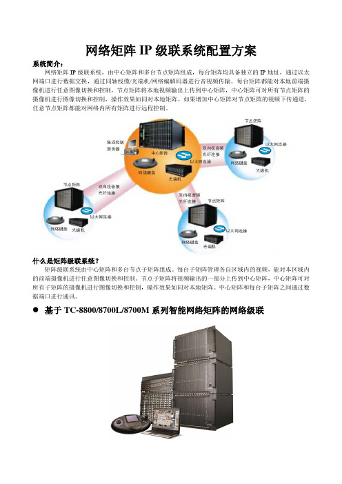
网络矩阵IP级联系统配置方案系统简介:网络矩阵IP级联系统,由中心矩阵和多台节点矩阵组成,每台矩阵均具备独立的IP地址,通过以太网端口进行数据交换,通过同轴线缆/光端机/网络编解码器进行音视频传输。
每台矩阵都能对本地前端摄像机进行任意图像切换和控制,节点矩阵将本地视频输出上传到中心矩阵,中心矩阵可对所有节点矩阵的摄像机进行图像切换和控制,操作效果如同对本地矩阵。
如果增加中心矩阵对节点矩阵的视频下传通道,任意节点矩阵都能对网络内所有矩阵进行远程控制。
什么是矩阵级联系统?矩阵级联系统由中心矩阵和多台节点子矩阵组成。
每台子矩阵管理各自区域内的视频,能对本区域内的前端摄像机进行任意图像切换和控制。
节点子矩阵将视频输出的一部分上传到中心矩阵,中心矩阵可对所有子矩阵的摄像机进行图像切换和控制,操作效果如同对本地矩阵。
中心矩阵和每台子矩阵之间通过数据端口进行通讯。
基于TC-8800/8700L/8700M系列智能网络矩阵的网络级联一、系统特点1、不仅可以支持3级以上的系统联网,更突破了传统矩阵模拟级联的结构限制,采用了IP路由方式的拓扑设计,实现了节点矩阵之间的任意交叉级联。
任何节点矩阵可观看其他节点矩阵的图像声音,任何节点矩阵可控制其他节点矩阵前端设备。
2、完全实时的异地控制和切换,快球/解码器操作灵活,定位准确,图像切换实时流畅。
3、联网报警的警情处理功能更完善,网络报警主机能同时将警情上传给本地矩阵和上级矩阵,警情监测双重保护更安全。
4、基于智能网络矩阵的混合联网,不仅具备视频监控功能,还可以扩展支持音频对讲功能。
5、双向视频/双向音频可通过线缆/光纤传输、实时同步、无损高清晰。
远距离联网可通过网络编解码器传输。
6、通讯数据通过以太网传输,分级权限管理,跨辖区指挥调度灵活快捷。
7、适用于平安城市、监狱看守所、高速公路、住宅小区、港口码头、厂矿仓库二、核心技术:1、B/S架构的虚拟管理中心,任意节点可对整个网络内的矩阵进行设置维护和远程升级。
网络键盘的操作方法

网络键盘的操作方法网络键盘是一种通过网络连接到计算机或其他设备的输入设备,可以远程控制目标设备进行操作。
网络键盘的操作方法主要包括连接网络、登录目标设备、进行键盘操作等步骤。
首先,要使用网络键盘,需要将其连接到网络。
一般来说,网络键盘可以通过有线网络连接或无线网络连接到目标设备。
有线连接时,可以使用网线将网络键盘与路由器或交换机连接起来;无线连接时,可以通过Wi-Fi或蓝牙等无线网络连接到目标设备。
连接完成后,网络键盘就可以和目标设备进行通信了。
接下来,就是登录目标设备。
在使用网络键盘之前,需要先登录目标设备,获得操作权限。
这一步取决于具体的目标设备,如果是连接到个人电脑或服务器,可能需要输入用户名和密码进行登录;如果是连接到路由器或交换机,可能需要输入管理账号和密码进行登录。
登录成功后,就可以开始使用网络键盘来远程控制目标设备了。
最后,就是进行键盘操作。
使用网络键盘进行键盘操作和使用普通键盘没有太大的区别,可以进行打字、快捷键操作、组合键操作等。
只不过,网络键盘的输入会通过网络传输到目标设备上,所以有时会受到网络延迟的影响,需要稍微注意一下。
除了以上的基本操作方法,网络键盘还有一些特殊的功能和操作方式。
比如,一些网络键盘还支持多设备切换,可以将一个网络键盘连接到多个设备上,通过快捷键切换不同的目标设备进行操作;一些网络键盘还支持远程复制粘贴功能,可以在不同的设备之间复制粘贴文本、图片等内容。
此外,由于网络键盘可以远程连接到目标设备,还可以通过一些远程桌面软件或远程控制软件来实现更多的功能和操作。
比如,可以通过远程桌面软件来实现远程桌面显示,将目标设备的屏幕显示在本地设备上,进行更加直观的操作;可以通过远程控制软件来实现远程文件传输、远程开关机、远程截图等功能。
总的来说,网络键盘的操作方法和普通键盘没有太大的差别,主要是连接网络、登录目标设备、进行键盘操作这几个基本步骤。
除了基本的操作方法外,还可以根据具体的网络键盘型号和目标设备类型来使用更多的功能和操作方式,实现更加便捷和高效的远程控制操作。
2.4G无线便携多媒体触控演讲键盘使用手册说明书

Mini Multimedia Wireless Presentation Keyboard User ManualV1.33Ver.:V1.OverviewThis device is a2.4G mini wireless QWERT keyboard, touchpad combo,with multi-system supported USB interface.By advanced capacitance sense technology, notebook touchpad experience can be enjoyed. Besides traditional wireless keyboard inputting feature,it supports multimedia remote control,wireless PC game control,touchpad functioning as a mouse,Touch pad90 degree flip,Power indicator,RF signal indicator, CAPSLOCK indicator,Low power warning indicator.(Only for Reference)Packing DetailThe following items are included(maybe slightly different for different distributors)Wireless Keyboard Mouse Main Unit•Wireless Receiver•Charging and Data Cable•User Manual•Windows2000•Windows XP•Windows Vista,Win CE,Win7,Win8•Linux(Debian-3.1,Redhat-9.0Ubuntu-8.10Fedora-7.0tested)•Android OS(With standard USB interface)by connecting to the computer,etc.Turn on/off the Backlit LED(O nly for A/B versions) Two Modes:Software Control and Manual Control When the wireless connection is successful,the backlit LED will be automatically on3seconds,then off,to savepower and lengthen standby time.You can click the backlit LED button to turn the LED ers can turn on the LED in dark environment for better operation.Sleep and Wake UpSleep mode is supported,to save power and lengthen standby time.If there is no operation more than3minutes, the device will enter sleep mode,with Backlit LED off,RF indicator on.In sleep mode,one random click on the keys can wake up the device.T urn off the D evice after U seAfter use,push the Power Switch to OFF position to turn it off.2.4G receiver should be plugged out and placed back to the receiver chamber for future use.Charging the BatteryThis device adopts built-in Polymer Lithium-ion battery. Please use the cables and chargers approved by my company.Not t e:For initial operation,the battery should be fullyNocharged.Use the portable charger:1.Connect the charger to the device.2.Connect the charger to the power supply or connect the charging cable to computer USB port.3.After about1hour(if the power is exhausted,longer time is required),upper left charging indicator will be on. When the charging is finished,plug out the charger or disconnect USB connection to the computer,and remove the charging cable from the device.NotNote e:You can use the device when charging,but charging time will be extended.When the power is low,the low voltage indicator will warn.If the power is to be exhausted,the device will be off.Use the L aser P ointer(only for A/B versions)Push the Power Switch to ON to turn on the device(2.4G receiver is not required to connect)and make the following operation:When you want to use laser pointer,press and hold the laser pointer switch to turn it on;remove your finger from the switch to turn it off.Care and MaintenanceOn Battery Use•Do not attempt to disassemble the device and replace battery.Doing so will void your warranty.•Charging time depends on battery capacity,type and charger type.Battery can be charged hundreds or thousands of times,but will be useless finally.When the battery life is apparently shortened,please contact the local distributor for battery replacement.•Battery automatically discharges for some specific time if no operation after fully-charged.•Do not place the device in extremely hot or cold environment,such as locked car in summer or winter.This will shorten battery life.Please try to keep it in normal temperature.If the battery is too hot or too cold,the device may not work even though it is fully-charged.Lithium battery performance will be affected if the temperature is under zero.MaintenanceThis device is designed by excellent designers.The following tips can help you to lengthen the device life.In operation:•Place the device and its accessories out of Childrenreach.•Touch pad is fragile.Strong impact and sharp item scratch will damage the touch feature.•Do not place it in over heat environment.High temperature will shorten the electronics product life.•Do not place it in extremely cold environment. Temperature rising may cause internal watery,to damage device circuit board.•If the device,battery,charger or any other accessories can not work,please resort to qualified repair service.DeclarationThis device wireless transmission frequency is2.4GHz, compliant with European R&TTE Directive1999/5/EC, whose radiation does no harm to human(far less than mobile phones).Wireless transmission produces electromagnetic signal.In environment where are heart pacemaker or related assistance equipment,the use of this device should be done with caution.The device uses2.4G wireless connection,subject to interference from other electronics products or obstacles; for best signal transmission,please remove the obstacles. DisclaimerWe have tried our best to make manual information correct and complete.If there is mistake or information missing, we are not responsible for any loss.And we keep the right to alter the user manual information without prior notification.。
社区监控系统项目设计方案

社区监控系统项目设计方案一、工程概况本工程拟对XXX社区的四个主要十字路口安装闭路电视监控系统,通过建立和运用电视监控系统,能有效地提高对主要交通干道和主要公共场所的动态控制、管理能力,增强处理社会治安突发事件的力度,对犯罪分子进行有力的威慑,给社区良好的社会治安提供了有力的保障,同时促进社会经济的发展。
二、用户需求根据XXX社区现有状况,需对社区周边四个主要十字路口来往车辆及行人重点监控,并能达到平时可控、事后可查的目的。
二、设计原则和设计依据1、设计原则(1)、先进性:在投资费用许可的情况下,系统采用当今较先进的技术和设备;(2)、可靠性:系统最重要的就是可靠性,系统一旦瘫痪的后果将是难以想象的。
系统设计时,在成本费用能接受的条件下,应从系统结构、设备选型、产品供应商的技术服务及维修响应能力等各方面严格要求,使故障发生的可能性尽可能少。
即便是出现故障时,影响面也要尽可能小;(3)、安全性:对于安全防系统,其本身的安全性能不可忽视,系统设计时,必须采取多种手段防止对本系统非法破坏。
(4)、可扩充性:系统设计时应充分考虑今后的发展需要,系统应具有预备容量的扩充与升级换代的可能;(5)、规性:由于本系统是一个严格的综合性系统,在系统的设计与施工过程中应参考各方面的标准与规,严格遵从各项技术规定,做好系统的标准化设计与施工。
2、设计依据⑴、GB/T50348—2004《安全防工程技术规》⑵、GA/T367-2001《视频安防监控系统技术要求》⑶、GA308-2001《安全防系统验收规则》三、视频监控系统基本设计思路前端监控设备采用模拟视频线缆、电源线缆、控制线缆引至摄像机立杆的设备箱中光端机,由光纤引至XXX楼控制中心,将视频还原为模拟信号接入数字硬盘录像机进行集中存储,并可通过中心控制键盘对前端设备进行操控(变倍、方向等)。
前端设备采用集中供电,前端变压的供电方式。
四、前端设备的分布根据建设方要求及现场勘测,拟对社区四个十字路口各安装一台红外高速球型摄像机,不仅可以满足大围的监控辐射,还可以保证在夜间清楚的捕捉目标。
戴尔 Precision 5820 塔式机 Wi-Fi 蓝牙模块安装指南说明书

Dell Precision 5820 T owerWi-Fi Bluetooth Module Installation GuideNotes, cautions, and warningsNOTE: A NOTE indicates important information that helps you make better use of your product.CAUTION: A CAUTION indicates either potential damage to hardware or loss of data and tells you how to avoid the problem.WARNING: A WARNING indicates a potential for property damage, personal injury, or death.© 2019 Dell Inc. or its subsidiaries. All rights reserved. Dell, EMC, and other trademarks are trademarks of Dell Inc. or its subsidiaries. Other trademarks may be trademarks of their respective owners.2019 - 02Rev. A001 Before you begin (4)Safety instructions (4)Before working inside your computer (4)Safety precautions (5)Electrostatic discharge—ESD protection (5)ESD field service kit (6)Transporting sensitive components (7)After working inside your computer (7)2 Wi-Fi Bluetooth (8)Wi-Fi Bluetooth Module installation kit (8)Installing the Wi-Fi Bluetooth Module for Precision 5820 Tower (8)3 Getting help (20)Contacting Dell (20)Contents3Before you begin Safety instructionsUse the following safety guidelines to protect your computer from potential damage and to ensure your personal safety. Unless otherwise noted, each procedure included in this document assumes that the following conditions exist:•You have read the safety information that shipped with your computer.•A component can be replaced or, if purchased separately, installed by performing the removal procedure in reverse order. WARNING: Disconnect all power sources before opening the computer cover or panels. After you finish working inside thecomputer, replace all covers, panels, and screws before connecting to the power source.WARNING: Before working inside your computer, read the safety information that shipped with your computer. For additional safety best practices information, see the Regulatory Compliance HomepageCAUTION: Many repairs may only be done by a certified service technician. You should only perform troubleshooting and simple repairs as authorized in your product documentation, or as directed by the online or telephone service and support team.Damage due to servicing that is not authorized by Dell is not covered by your warranty. Read and follow the safety instructions that came with the product.CAUTION: T o avoid electrostatic discharge, ground yourself by using a wrist grounding strap or by periodically touching an unpainted metal surface at the same time as touching a connector on the back of the computer.CAUTION: Handle components and cards with care. Do not touch the components or contacts on a card. Hold a card by its edges or by its metal mounting bracket. Hold a component such as a processor by its edges, not by its pins.CAUTION: When you disconnect a cable, pull on its connector or on its pull-tab, not on the cable itself. Some cables have connectors with locking tabs; if you are disconnecting this type of cable, press in on the locking tabs before you disconnect the cable. As you pull connectors apart, keep them evenly aligned to avoid bending any connector pins. Also, before you connect acable, ensure that both connectors are correctly oriented and aligned.NOTE: The color of your computer and certain components may appear differently than shown in this document.CAUTION: System will shut down if side covers are removed while the system is running. The system will not power on if the side cover is removed.Before working inside your computer1 Ensure that your work surface is flat and clean to prevent the computer cover from being scratched.2 Turn off your computer.3 Disconnect all network cables from the computer (if available).CAUTION: If your computer has an RJ45 port, disconnect the network cable by first unplugging the cable from yourcomputer.4 Disconnect your computer and all attached devices from their electrical outlets.5 Open the display.6 Press and hold the power button for few seconds, to ground the system board.CAUTION: To guard against electrical shock unplug your computer from the electrical outlet before performing Step #8.CAUTION: To avoid electrostatic discharge, ground yourself by using a wrist grounding strap or by periodically touchingan unpainted metal surface at the same time as touching a connector on the back of the computer.1 4Before you begin7 Remove any installed ExpressCards or Smart Cards from the appropriate slots.Safety precautionsThe safety precautions chapter details the primary steps to be taken before performing any disassembly instructions.Observe the following safety precautions before you perform any installation or break/fix procedures involving disassembly or reassembly:•Turn off the system and all attached peripherals.•Disconnect the system and all attached peripherals from AC power.•Disconnect all network cables, telephone, and telecommunications lines from the system.•Use an ESD field service kit when working inside any desktop to avoid electrostatic discharge (ESD) damage.•After removing any system component, carefully place the removed component on an anti-static mat.•Wear shoes with non-conductive rubber soles to reduce the chance of getting electrocuted.Standby powerDell products with standby power must be unplugged before you open the case. Systems that incorporate standby power are essentially powered while turned off. The internal power enables the system to be remotely turned on (wake on LAN) and suspended into a sleep mode and has other advanced power management features.Unplugging, pressing and holding the power button for 15 seconds should discharge residual power in the system board. . BondingBonding is a method for connecting two or more grounding conductors to the same electrical potential. This is done through the use of a field service electrostatic discharge (ESD) kit. When connecting a bonding wire, ensure that it is connected to bare metal and never to a painted or non-metal surface. The wrist strap should be secure and in full contact with your skin, and ensure that you remove all jewelry such as watches, bracelets, or rings prior to bonding yourself and the equipment.Electrostatic discharge—ESD protectionESD is a major concern when you handle electronic components, especially sensitive components such as expansion cards, processors, memory DIMMs, and system boards. Very slight charges can damage circuits in ways that may not be obvious, such as intermittent problems or a shortened product life span. As the industry pushes for lower power requirements and increased density, ESD protection is an increasing concern.Due to the increased density of semiconductors used in recent Dell products, the sensitivity to static damage is now higher than in previous Dell products. For this reason, some previously approved methods of handling parts are no longer applicable.Two recognized types of ESD damage are catastrophic and intermittent failures.•Catastrophic – Catastrophic failures represent approximately 20 percent of ESD-related failures. The damage causes an immediate and complete loss of device functionality. An example of catastrophic failure is a memory DIMM that has received a static shock and immediately generates a "No POST/No Video" symptom with a beep code emitted for missing or nonfunctional memory.•Intermittent – Intermittent failures represent approximately 80 percent of ESD-related failures. The high rate of intermittent failures means that most of the time when damage occurs, it is not immediately recognizable. The DIMM receives a static shock, but the tracing is merely weakened and does not immediately produce outward symptoms related to the damage. The weakened trace may take weeks or months to melt, and in the meantime may cause degradation of memory integrity, intermittent memory errors, etc.The more difficult type of damage to recognize and troubleshoot is the intermittent (also called latent or "walking wounded") failure. Perform the following steps to prevent ESD damage:Before you begin5•Use a wired ESD wrist strap that is properly grounded. The use of wireless anti-static straps is no longer allowed; they do not provide adequate protection. T ouching the chassis before handling parts does not ensure adequate ESD protection on parts with increased sensitivity to ESD damage.•Handle all static-sensitive components in a static-safe area. If possible, use anti-static floor pads and workbench pads.•When unpacking a static-sensitive component from its shipping carton, do not remove the component from the anti-static packing material until you are ready to install the component. Before unwrapping the anti-static packaging, ensure that you discharge static electricity from your body.•Before transporting a static-sensitive component, place it in an anti-static container or packaging.ESD field service kitThe unmonitored Field Service kit is the most commonly used service kit. Each Field Service kit includes three main components: anti-static mat, wrist strap, and bonding wire.Components of an ESD field service kitThe components of an ESD field service kit are:•Anti-Static Mat – The anti-static mat is dissipative and parts can be placed on it during service procedures. When using an anti-static mat, your wrist strap should be snug and the bonding wire should be connected to the mat and to any bare metal on the system being worked on. Once deployed properly, service parts can be removed from the ESD bag and placed directly on the mat. ESD-sensitive items are safe in your hand, on the ESD mat, in the system, or inside a bag.•Wrist Strap and Bonding Wire – The wrist strap and bonding wire can be either directly connected between your wrist and bare metal on the hardware if the ESD mat is not required, or connected to the anti-static mat to protect hardware that is temporarily placed on the mat. The physical connection of the wrist strap and bonding wire between your skin, the ESD mat, and the hardware is known as bonding. Use only Field Service kits with a wrist strap, mat, and bonding wire. Never use wireless wrist straps. Always be aware that the internal wires of a wrist strap are prone to damage from normal wear and tear, and must be checked regularly with a wrist strap tester in order to avoid accidental ESD hardware damage. It is recommended to test the wrist strap and bonding wire at least once per week.•ESD Wrist Strap Tester – The wires inside of an ESD strap are prone to damage over time. When using an unmonitored kit, it is a best practice to regularly test the strap prior to each service call, and at a minimum, test once per week. A wrist strap tester is the best method for doing this test. If you do not have your own wrist strap tester, check with your regional office to find out if they have one.T o perform the test, plug the wrist-strap's bonding-wire into the tester while it is strapped to your wrist and push the button to test. A green LED is lit if the test is successful; a red LED is lit and an alarm sounds if the test fails.•Insulator Elements – It is critical to keep ESD sensitive devices, such as plastic heat sink casings, away from internal parts that are insulators and often highly charged.•Working Environment – Before deploying the ESD Field Service kit, assess the situation at the customer location. For example, deploying the kit for a server environment is different than for a desktop or portable environment. Servers are typically installed in a rack within a data center; desktops or portables are typically placed on office desks or cubicles. Always look for a large open flat work area that is free of clutter and large enough to deploy the ESD kit with additional space to accommodate the type of system that is being repaired. The workspace should also be free of insulators that can cause an ESD event. On the work area, insulators such as Styrofoam and other plastics should always be moved at least 12 inches or 30 centimeters away from sensitive parts before physically handling any hardware components•ESD Packaging – All ESD-sensitive devices must be shipped and received in static-safe packaging. Metal, static-shielded bags are preferred. However, you should always return the damaged part using the same ESD bag and packaging that the new part arrived in.The ESD bag should be folded over and taped shut and all the same foam packing material should be used in the original box that the new part arrived in. ESD-sensitive devices should be removed from packaging only at an ESD-protected work surface, and parts should never be placed on top of the ESD bag because only the inside of the bag is shielded. Always place parts in your hand, on the ESD mat, in the system, or inside an anti-static bag.•Transporting Sensitive Components – When transporting ESD sensitive components such as replacement parts or parts to be returned to Dell, it is critical to place these parts in anti-static bags for safe transport.ESD protection summaryIt is recommended that all field service technicians use the traditional wired ESD grounding wrist strap and protective anti-static mat at all times when servicing Dell products. In addition, it is critical that technicians keep sensitive parts separate from all insulator parts while performing service and that they use anti-static bags for transporting sensitive components.6Before you beginTransporting sensitive componentsWhen transporting ESD sensitive components such as replacement parts or parts to be returned to Dell, it is critical to place these parts in anti-static bags for safe transport.Lifting equipmentAdhere to the following guidelines when lifting heavy weight equipment:CAUTION: Do not lift greater than 50 pounds. Always obtain additional resources or use a mechanical lifting device.1Get a firm balanced footing. Keep your feet apart for a stable base, and point your toes out.2Tighten stomach muscles. Abdominal muscles support your spine when you lift, offsetting the force of the load.3Lift with your legs, not your back.4Keep the load close. The closer it is to your spine, the less force it exerts on your back.5Keep your back upright, whether lifting or setting down the load. Do not add the weight of your body to the load. Avoid twisting your body and back.6Follow the same techniques in reverse to set the load down.After working inside your computerAfter you complete any replacement procedure, ensure that you connect external devices, cards, and cables before turning on your computer.CAUTION: T o avoid damage to the computer, use only the battery designed for this particular Dell computer. Do not use batteries designed for other Dell computers.1 Connect any external devices, such as a port replicator or media base, and replace any cards, such as an ExpressCard.2 Connect any telephone or network cables to your computer.CAUTION: To connect a network cable, first plug the cable into the network device and then plug it into thecomputer.3 Connect your computer and all attached devices to their electrical outlets.4 Turn on your computer.Before you begin7Wi-Fi BluetoothWi-Fi Bluetooth Module installation kitThe following components are required to install the Wi-Fi/ Bluetooth (BT) module:1Wi-Fi/BT PCIe adapter card 2Wi-Fi card screw 3Wi-Fi card bracket 4Wi-Fi card 5Wi-Fi/BT PCIe adapter card cable 6External antenna7Plastic cover Installing the Wi-Fi Bluetooth Module for Precision 5820 Tower1Follow the procedure in before working inside your computer .2 To install the Wi-Fi card into the Wi-Fi/Bluetooth (BT) PCIe adapter card:aAlign and insert the Wi-Fi card into the slot on the Wi-Fi/BT PCIe adapter card [1].bConnect the antenna cables to the Wi-Fi card [2].cAlign the Wi-Fi card bracket on the Wi-Fi card [3].d Tighten the single screw (M2x2.5) to secure both the Wi-Fi card bracket and Wi-Fi card to the Wi-Fi/BT PCIe adapter card [4].28Wi-Fi BluetoothWi-Fi Bluetooth94 To remove the side cover:a Press the latch.10Wi-Fi BluetoothWi-Fi Bluetooth115 To remove the PCIe card holder:•If full length cards are installed, you will need to remove these cards before removing the holder.•If MegaRAID 9460 is installed, disconnect the Super CAP from the card before removing the PCIe card holder from the system.a Disconnect the two power cables from the cable slot in the PCIe holder [1].b Press the PCIe holder securing clip and slide the holder [2] out of the chassis.12Wi-Fi Bluetooth6 To remove the filler bracket:a Press and rotate the PCI latch backward [1] to unlock the filler bracket.b Remove the filler bracket from the slot on the system [2].Wi-Fi Bluetooth1314Wi-Fi Bluetooth8 To connect the Wi-Fi/BT PCIe adapter card cable:a Lock both the PCI latch brackets forward on the filler bracket to secure the Wi-Fi/BT PCIe adapter card to the system board [1].b Route the Wi-Fi/BT PCIe adapter card cable through to the routing channels on the system [2].c Connect other end of the Wi-Fi/BT PCIe adapter card cable socket to the connector on the system board [3].Wi-Fi Bluetooth159 To install the PCIe holder:a Align and place the PCIe holder to the system chassis [1]. Then, press the holder back until it clicks to the system.b Connect the two power cables to the cable slots in the holder [2].•If the MegaRAID 9460 was removed, please connect the Super CAP back to the card.•Reinstall the full length cards if they were removed.16Wi-Fi BluetoothWi-Fi Bluetooth1711 To install the external antenna:a Pass the external antenna cables through the openings on the plastic cover [1].b Fasten antenna cables to Wi-Fi/BT PCIe adapter card [2].c Tighten the single screw to secure the plastic cover to the PCI panel [3].18Wi-Fi BluetoothWi-Fi Bluetooth19Getting helpContacting DellNOTE: If you do not have an active Internet connection, you can find contact information on your purchase invoice, packing slip, bill, or Dell product catalog.Dell provides several online and telephone-based support and service options. Availability varies by country and product, and some services may not be available in your area. T o contact Dell for sales, technical support, or customer service issues:1Go to /support.2Select your support category.3Verify your country or region in the Choose a Country/Region drop-down list at the bottom of the page.4 Select the appropriate service or support link based on your need.320Getting help。
戴尔无线键盘和鼠标快速入门指南说明书
Set up the keyboard and mouse设置键盘和鼠标設定鍵盤和滑鼠Memasang keyboard dan mouseキーボードとマウスをセットアップする14Finish Windows setup完成 Windows 设置 | 完成 Windows 設定Selesaikan penataan Windows | Windows セットアップを終了するEnable security and updates启用安全和更新功能啟用安全性與更新Aktifkan pengamanan danpemutakhiranセキュリティとアップデートを有効にするSign in to your Microsoft account orcreate a local account登录 Microsoft 帐户或创建本地帐户登入您的 Microsoft 帳號或建立本機帳號Masuk ke dalam akun Microsoft Andaatau buat akun lokalMicrosoft アカウントにサインインする、またはローカルアカウントを作成するConnect to your network连接到网络連接網路Hubungkan ke jaringan Andaネットワークに接続するExplore resources浏览资源 | 探索資源Jelajahi sumber daya | リソースを検索するHelp and Tips帮助与提示 | 說明與秘訣Bantuan dan Tips | ヘルプとヒントMy Dell我的 Dell | 我的 DellDell Saya | マイデルRegister your computer注册计算机 | 註冊您的電腦Daftarkan komputer Anda | コンピュータを登録するSee the documentation that shipped with the wireless keyboardand mouse.请参阅无线键盘和鼠标随附的文档。
监控系统技术参数解析

第五章技术要求(1)摄像机高清红外网络球型摄像机:按现场情况实际需要,选用高清网络红外球型摄像机,该摄像机带网络模块、变焦镜头、高速预制云台、智能解码控制器、高分辨、带红外灯,确保能清晰监视各监控点图像。
高清红外网络枪型摄像机:按现场情况实际需要,选用3.3-12mm高清手动变焦镜头摄像机,支持背光补偿功能,强光抑制等功能,照射距离在30-50米之间。
(2)监控点立杆和基础要求前端监控点的立杆按实际情况而定,部分监控可以利用电力杆、墙壁等周边建筑设施;部分地方考虑单独立杆。
由于外部监控点受环境影响,立杆分球机立杆、借杆(挑杆)两种,各自要求如下:水上公园球机立杆方式:由于该区域比较广阔,立杆的要求比较高,高度要求6米左右,表面处理采用热镀锌钢管喷塑处理的方式,立杆的外型设计应和周界环境相协调。
参考图如下:借杆(壁装):阅海湾商务区服务中心外围的两个红外枪机借助服务区墙壁安装;阅海湾商务区服务中心外围球机立杆:该区域范围较小,立杆要求相对较低,高度建议为5米,表面处理采用热镀锌钢管喷塑处理的方式,立杆的外型设计应和周界环境相协调。
球机立杆示意图水上公园6米立杆示意图,包含壁挂箱,(3)监控点机箱和基础要求前端机箱要求能放置前端光接入设备, 采用优质冷扎钢板,热镀锌喷塑。
设计为离地300 mm高度落地安装。
箱体防护等级为IP54,防雨防尘,室外安装。
在监控机箱中应设计电源保护装置,即过流过压保护装置,里面开关电源设备、防雷模块、接线端子、光纤终端盒、维修开关和插座。
为了保证设备的安全,机箱大门采用防盗锁具,具有很强的防橇性能。
(4)监控点取电监控点采用统一供电的方式,供电应稳定可靠,供电电压达到:交流AC 220V;频率范围:46HZ-60HZ;电压范围:AC170V到280V;功率要求不小于1KW(包括监控点补光功率);全天候24小时确保前端设备的供电;要求采用室外供电电缆敷设;走地下标准强电管道;整个供电应当满足稳定可靠、扩展方便、可维护管理等特点。
- 1、下载文档前请自行甄别文档内容的完整性,平台不提供额外的编辑、内容补充、找答案等附加服务。
- 2、"仅部分预览"的文档,不可在线预览部分如存在完整性等问题,可反馈申请退款(可完整预览的文档不适用该条件!)。
- 3、如文档侵犯您的权益,请联系客服反馈,我们会尽快为您处理(人工客服工作时间:9:00-18:30)。
智能网络键盘安装使用手册目录第一章键盘简介 (1)1.1 功能特点 (1)1.2 产品外观 (1)1.3 技术指标 (2)第二章键盘安装 (4)2.1 接口说明 (4)2.2 安装连接 (5)第三章键盘设置 (7)3.1 概述 (7)3.2 本机登录 (7)3.3 键盘设置 (7)第四章矩阵控制 (13)4.1 登录矩阵 (13)4.2 矩阵控制界面 (13)4.3 切换操作 (13)4.4 前端控制 (14)4.5 报警控制 (14)4.6 宏操作 (14)4.7 快球控制 (15)4.8 群切操作 (16)4.9 场景操作 (16)4.10 越权控制 (17)4.11 开关操作 (17)4.12 锁定操作 (17)4.13 重新登录 (17)4.14 登录其它矩阵 (17)4.15 屏幕编程 (17)第五章前端直控控制 (18)5.1 登录前端直控 (18)5.2 前端直控界面 (18)5.3 切换摄像机 (18)5.4 前端控制 (19)第六章嵌入式DVR控制 (22)6.1 登录DVR设备 (22)6.2 CNTD协议控制(以太网/UDP方式) (22)6.3 CNHK协议控制(485方式/波特率9600) (24)6.4 CNDH1协议控制(485方式/波特率9600) (26)6.5 CNDH2协议控制(485方式/波特率9600) (28)附录:矩阵操作功能列表 (31)第一章键盘简介智能网络键盘是我公司推出的监控系统集成控制设备,支持中/英文操作界面和中/英文WEB设置界面,可以配合智能网络矩阵或嵌入式DVR使用,也可以直接控制RS-485通讯方式的前端球云台解码器。
1.1 功能特点●精细点阵大屏幕液晶显示屏●中/英文操作界面●矢量变速摇杆●英文硅胶按键背景光显示●在线提示信息●以太网/RS-485通讯●功能键图标驱动导航1.2 产品外观【图例1-1 网络键盘侧视图】①液晶显示屏:绿色背景光,中/英文操作界面可选,设备状态/编程信息实时显示。
②主按键区:橙色背景光。
【0】~【9】数字键【F1】~【F5】快捷键【CANCEL】取消键【ENTER】确定键【PREV】向前键,切换前一个编号的摄像机【NEXT】向后键,切换后一个编号的摄像机【PRESET】预置位功能键【LOCK】锁定键【SITE】设备选择键(控制DVR时,选择DVR的设备号)【MACRO】宏操作功能键【ALARM】消警功能键【ARM】布防/撤防功能键【PGM】编程键【SHIFT】组合键【MON】监视器切换键【CAM】摄像机切换键③镜头控制键区:【图例1-2 镜头控制键区】④矢量变速摇杆(分为二维和三维两种型号)1.3 技术指标工作温度:-10℃~50℃工作湿度:<90%工作电压:DC12V功耗:5WRS-485接口:2路以太网接口:10Base-T UDP(局域网)外形尺寸(mm): 345×175×98(长×宽×高)【图例1-3 键盘外观尺寸】第二章 键盘安装2.1 接口说明【图例2-1 键盘后视接口图】 ① MINI USB : 预留② RS-485: RS-485控制总线端口两路分配输出,用于控制球云台或嵌入式 DVR 时使用 ③ 拨码开关: 扩展功能预留 ④ RS-232: 扩展功能预留⑤ 网络接口: 连接网络矩阵和DVR ⑥ 电源输入: DC12V/1000mA⑦ 电源开关2.2 安装连接2.2.1 控制矩阵智能网络键盘可以控制智能网络矩阵,通过网线或者交换机将矩阵背部的网络接口与键盘背部的网络接口相连,接通键盘电源,开启电源开关,键盘液晶屏幕显示用户登录界面,选择矩阵设备,输入用户名和密码后即可使用。
正常登录矩阵前,需要在矩阵的WEB集控界面中添加智能网络键盘的IP地址,在键盘本机设置界面中添加智能网络矩阵的IP地址。
快速使用指南第一步:进入键盘本机设置界面,调整键盘的IP地址,在设备属性中添加智能网络矩阵的IP地址。
第二步:在智能网络矩阵的WEB设置界面中,添加当前智能网络键盘的IP地址和矩阵用户ID。
第三步:在键盘的设备登录界面中,选择要登录的智能网络矩阵的设备ID号,在矩阵登录界面中,输入矩阵用户ID(默认为1)和密码(默认为000000),进入矩阵控制界面。
第四步:在矩阵控制界面,输入前端摄像机的ID,按【CAM】键确认,可以切换出视频图像。
第五步:操控摇杆,可以对当前ID的前端云台进行上、下、左、右的云台操作,操作镜头按键,可以对摄像机进行镜头变倍等功能的操作。
如果不能控制,请在矩阵WEB设置界面中,检查当前摄像机的动静点属性地址和前端协议波特率。
2.2.2 控制球云台智能网络键盘可以直接控制RS-485通讯方式的球云台,用屏蔽双绞线将球云台的RS-485通讯线与键盘背部的RS-485接口相连,接通键盘电源,开启电源开关,键盘液晶屏幕显示用户登录界面,选择前端直控设备,输入键盘本机用户名和密码即可使用。
登录前,需要在键盘本机设置界面中添加前端直控设备,设置相应的协议和波特率。
快速使用指南第一步:进入键盘本机设置界面,在设备属性中添加前端直控设备,设置与前端直控设备对应正确的协议和波特率。
第二步:在键盘的设备登录界面中,选择要登录的前端直控设备ID号,在登录界面中,输入键盘本机的用户ID(默认为1)和密码(默认为000000),进入前端直控界面。
第三步:在前端直控界面,输入前端球云台的ID,按【CAM】键确认并更换当前点编号。
第四步:操控摇杆,可以对当前控制点进行上、下、左、右的云台操作,操作镜头按键,可以对摄像机进行镜头变倍聚焦等功能的操作。
2.2.3 控制嵌入式DVR智能网络键盘可以控制嵌入式DVR,支持四种主机协议:CNHK协议:RS-485接口,波特率9600。
CNDH1协议:RS-485接口,波特率9600。
CNDH2协议:RS-485接口,波特率9600。
CNTD协议:以太网接口,UDP方式。
CNHK/CNDH1/CNDH2协议:用屏蔽双绞线将DVR背部的键盘RS-485接口与智能网络键盘背部的RS-485接口相连,接通键盘电源,开启电源开关,键盘液晶屏幕显示用户登录界面,选择DVR设备,输入键盘本机用户名和密码即可使用。
登录前,需要在键盘本机设置界面中添加DVR设备,设置控制DVR的键盘ID号、控制协议和控制接口。
CNTD协议:通过网线或者交换机将DVR背部的网络接口与键盘背部的网络接口相连,接通键盘电源,开启电源开关,键盘液晶屏幕显示用户登录界面,选择DVR设备,输入键盘本机用户名和密码即可使用。
登录前,需要在键盘本机设置界面中添加DVR设备,设置控制DVR的键盘ID号、控制协议和控制接口。
快速使用指南第一步:进入键盘本机设置界面,在设备属性中添加DVR设备,设置控制DVR的键盘ID号、控制协议和控制接口。
第二步:在键盘的设备登录界面中,选择要登录的DVR设备ID号,在登录界面中,输入键盘本机的用户ID(默认为1)和密码(默认为000000),进入DVR界面。
第三章键盘设置3.1 概述如果您第一次使用智能网络键盘,请仔细阅读本章内容,本章节将指导您设置键盘本机的网络属性、控制设备属性,完成键盘的硬件功能设置和硬件测试。
键盘液晶屏上显示的软按键图标与键盘上【F1】~【F5】快捷键对应,按快捷键实现软按键的功能。
说明书中软按键用< >表示。
3.2 本机登录按住【PGM】键的同时给键盘上电,则会进入键盘本机的设置登录界面。
输入正确的用户名和密码才能登录。
键盘本机支持4个用户(用户ID分别为1、2、3、4),密码为6位数字,出厂默认密码都是000000。
【图例3-1 键盘设置登录界面】3.3 键盘设置在设置界面中可以修改键盘本机的IP地址和子网掩码等网络参数,设置控制设备的相关属性,调整键盘本身的背光和按键音,测试键盘的按键摇杆等。
【图例3-2 键盘功能设置】3.3.1 网络属性设置按软按键<网络>进入网络属性设置,设置键盘自身的IP地址、子网掩码、网关、MAC 地址。
【图例3-3 键盘网络属性设置】按相应功能的软按键,进入修改界面,按数字键修改光标焦点位置的数值。
按【PREV 】键向前移动焦点,按【NEXT 】、【ENTER 】键向后移动焦点。
按<退出>键返回上一级菜单。
【图例3-4设置键盘网络参数】修改完成后按<保存>键,键盘返回提示信息后按【ENTER 】或<退出>键返回。
【图例3-5 保存键盘网络参数】3.3.2 设备属性设置在键盘功能设置界面(见图例3-2),按<设备>键进入设备属性设置界面。
每个键盘支持最多控制10个设备(设备ID 号为1-10),每个设备可以被设置为“无设备”、“矩阵”、“前端直控”、“DVR ”中的任意一种。
在设备输入框中输入ID 号,按【ENTER 】键确认。
【图例3-6 网络设备属性设置】在类型选择框中按【PREV 】、【NEXT 】键选择控制设备,按【ENTER 】键确认,然后进入相应设备的属性设置界面。
选择前端直控设备后,进入前端直控属性设置界面。
需要设置通信协议和波特率。
按【PREV 】、【NEXT 】键选择通讯协议或波特率。
按【ENTER 】键将光标焦点移到波特率选项上,按【CANCEL 】键将光标焦点移到通讯协议选项上。
设置完成按<保存>键保存。
支持10种主流快球通讯协议:PELCO_P 、PELCO_D 、TIANDY 、XTS 、MOLYNX 、SAMSUNG1、SAMSUNG2、SONYD70、PANASONIC 、DAHUA 。
支持四种通讯波特率:2400bps 、4800bps 、9600bps 、19200bps 。
【图例3-7设置前端直控参数】选择DVR 设备后,进入DVR 属性设置界面。
需要设置控制DVR 的键盘编号(KBD ID 号范围为1~16)、协议、接口。
设置完成按<保存>键保存。
【图例3-8 设置485控制DVR 的参数】【图例3-9 设置网络控制DVR 的参数】选择无设备后,按【ENTER 】键确认,提示保存完成,把当前设备编号设置成无设备的空闲状态。
【图例3-10 设置设备类型为“无设备”】3.3.3 键盘属性设置在键盘功能设置界面(见图例3-2),按<键盘>键进入键盘属性设置界面。
【图例3-11 键盘属性设置】修改用户密码按<密码>键进入键盘用户密码修改界面。
先输入用户号(键盘本机支持4个用户,编号1-4),按【ENTER】键将光标焦点移到密码输入框,输入原密码。
原密码确认正确后,才可以输入新密码。