MCL-A+Series+of+Multilayer+Chip+Ferrite+Inductor
MCL1608V1Multilayer Chip Inductor产品说明书

MCL1608V1 Multilayer chip inductorProduct features• 0603 (1608 metric) package• Low DC resistance, high current• Multilayer monolithic construction yields high reliability• Suitable for wave and reflow soldering• Inductance range from 0.047 uH to 12 uH • Moisture sensitivity level (MSL): 1Applications• Industrial connectivity (IoT)• Wireless communiations• Bluetooth• WiFi• Antenna• Machine-to-machine (M2M)• Mobile phones• Wearable devices• Wireless LAN• Computing/gaming consoles• Broadband components• RF transciever modulesEnvironmental data• Operating temperature range: -40 °C to +85 °C (ambient plus self-temperature rise)• Solder reflow temperature:J-STD-020 (latest revision) compliantPb HALOGENHFFREE2Technical Data 10926Effective June 2019MCL1608V1Multilayer chip inductor/electronicsProduct specificationsPart numberOCL(uH) ±20%I Rated(mA) maximumDCR (Ω)maximum @ +25°CSRF(MHz) minimumTest frequency (MHz)Test voltage (mV)MCL1608V1-R047-R 0.0471500.12260 1.050MCL1608V1-R056-R 0.0561500.12260 1.050MCL1608V1-R068-R 0.0681500.12250 1.050MCL1608V1-R082-R 0.0821500.12245 1.050MCL1608V1-R10-R 0.1001500.15240 1.050MCL1608V1-R12-R 0.1201500.20205 1.050MCL1608V1-R15-R 0.1501500.20180 1.050MCL1608V1-R18-R 0.1801500.20165 1.050MCL1608V1-R22-R 0.2201500.25150 1.050MCL1608V1-R27-R 0.2701000.30136 1.050MCL1608V1-R33-R 0.3301000.30125 1.050MCL1608V1-R39-R 0.3901000.35110 1.050MCL1608V1-R47-R 0.4701000.45105 1.050MCL1608V1-R56-R 0.5601000.4595 1.050MCL1608V1-R68-R 0.6801000.5590 1.050MCL1608V1-R82-R 0.8201000.6085 1.050MCL1608V1-1R0-R 1.0 1500.3075 1.050MCL1608V1-1R2-R 1.21500.3065 1.050MCL1608V1-1R5-R 1.51200.3560 1.050MCL1608V1-1R8-R 1.81200.4055 1.050MCL1608V1-2R2-R 2.21200.5050 1.050MCL1608V1-2R7-R 2.71000.6045 1.050MCL1608V1-3R3-R 3.31000.6540 1.050MCL1608V1-3R9-R 3.9800.7035 1.050MCL1608V1-4R7-R 4.7800.7533 1.050MCL1608V1-5R6-R 5.6600.9022 1.050MCL1608V1-6R8-R 6.8600.9020 1.050MCL1608V1-8R2-R 8.260 1.0518 1.050MCL1608V1-100-R 1060 1.1517 1.050MCL1608V1-120-R12601.25151.0501. Test frequency and voltage at +25 °C2. Resistance to soldering heat: +260 ±5 °C for 10 ± 1 second3. At low temperature (-40 ±2°C) the inductance change is within ±10%4. At high temperature (+85 ±2°C) the inductance change is within ±10%5. Rated I: When rated I is applied to the product, self-temperature rise will be 40 °C or less.6. Part Number Definition: MCL1608V1-xxx-R MCL1608 = Product code and size V1= Version indicatorxxx= inductance value in uH, R= decimal point,If no R is present then last character equals number of zeros -R suffix = RoHS compliant3Technical Data 10926Effective June 2019MCL1608V1Multilayer chip inductor /electronics No part markingAll soldering surfaces to be coplanar within 0.1 millimeters Tolerances are ±0.2 millimeters unless stated otherwisePad layout tolerances are ±0.1 millimeters unless stated otherwise Do not route traces or vias underneath the inductorDimensions (mm)SchematicPart Number L W T a A B CMCL1608V1-xxx-R 1.6 ±0.200.80 ±0.200.80 ±0.200.30 ±0.20 1.2 ±0.100.9 ±0.10040 ±0.10Packaging information (mm)Drawing not to scaleSupplied in tape and reel packaging, 4000 parts per 7” diameter reelW ±0.38.00F±0.05 3.50E1±0.10 1.75E2 Min 6.25P0±0.10 4.00P1±0.20 4.00P2±0.1 2.001.50D0+0.10/-0A0 1.1±0.20B0 1.9±0.20T Max 1.10T1 Max na4Technical Data 10926Effective June 2019MCL1608V1Multilayer chip inductor/electronicsInductance vs frequency24681012I n d u c t a n c e [u H ]Q vs frequency102030405060Q v a l u eFrequency [MHz]Inductance vs current1101001,00010,000I n d u c t a n c e (n H )Current (mAdc)MCL1608V1-100-R MCL1608V1-R39-R MCL1608V1-2R2-RTemperature rise vs current102030405060708090T e m p e r a t u r e r i s e (°C )Current (Adc)5Technical Data 10926Effective June 2019MCL1608V1Multilayer chip inductor /electronics Solder reflow profileTable 1 - Standard SnPb solder (T c )Package ThicknessVolume mm3 <350Volume mm3 ≥350<2.5 mm)235 °C 220 °C ≥2.5 mm220 °C220 °CTable 2 - Lead (Pb) free solder (T c )Package thicknessVolume mm 3 <350Volume mm 3350 - 2000Volume mm 3 >2000<1.6 mm 260 °C 260 °C 260 °C 1.6 – 2.5 mm 260 °C 250 °C 245 °C >2.5 mm250 °C245 °C245 °CT e m p e r a t u r eT LT PReference J-STD-020Profile featureStandard SnPb solderLead (Pb) free solderPreheat and soak • Temperature min. (T smin )100 °C 150 °C • Temperature max. (T smax )150 °C 200 °C • Time (T smin to T smax ) (t s )60-120 seconds 60-120 seconds Average ramp up rate T smax to T p 3 °C/ second max. 3 °C/ second max.Liquidous temperature (T l ) Time at liquidous (t L )183 °C60-150 seconds 217 °C60-150 seconds Peak package body temperature (T P )*Table 1Table 2Time (t p )** within 5 °C of the specified classification temperature (T c )10 seconds**10 seconds**Average ramp-down rate (T p to T smax ) 6 °C/ second max. 6 °C/ second max.Time 25 °C to peak temperature6 minutes max.8 minutes max.* Tolerance for peak profile temperature (T p ) is defined as a supplier minimum and a user maximum.** Tolerance for time at peak profile temperature (t p ) is defined as a supplier minimum and a user maximum.EatonElectronics Division 1000 Eaton Boulevard Cleveland, OH 44122United States/electronics © 2019 EatonAll Rights Reserved Printed in USAPublication No. 10926 BU-MC19058June 2019MCL1608V1Multilayer chip inductorTechnical Data 10926Effective June 2019Life Support Policy: Eaton does not authorize the use of any of its products for use in life support devices or systems without the express writtenapproval of an officer of the Company. Life support systems are devices which support or sustain life, and whose failure to perform, when properly used in accordance with instructions for use provided in the labeling, can be reasonably expected to result in significant injury to the user.Eaton reserves the right, without notice, to change design or construction of any products and to discontinue or limit distribution of any products. Eaton also reserves the right to change or update, without notice, any technical information contained in this bulletin.T e m p e r a t u r eTimeT T T T Wave solder profileReference EN 61760-1:2006Profile featureStandard SnPb solderLead (Pb) free solderPreheat • Temperature min. (T smin )100 °C 100 °C • Temperature typ. (T styp )120 °C 120 °C • Temperature max. (T smax )130 °C 130 °C • Time (T smin to T smax ) (t s )70 seconds 70 seconds D preheat to max Temperature150 °C max.150 °C max.Peak temperature (T P )*235 °C – 260 °C 250 °C – 260 °C Time at peak temperature (t p )10 seconds max5 seconds max each wave 10 seconds max5 seconds max each wave Ramp-down rate~ 2 K/s min ~3.5 K/s typ ~5 K/s max ~ 2 K/s min ~3.5 K/s typ~5 K/s max Time 25 °C to 25 °C4 minutes4 minutesManual solder+350 °C, 4-5 seconds. (by soldering iron), generally manual, hand soldering is not recommended.Eaton is a registered trademark.All other trademarks are property of their respective owners.Follow us on social media to get the latest product and support information.。
Sunlord 电感 SDFL系列

用途
● 广泛运用于通讯、视频/音频、计算机、遥控 器等领域
APPLICATIONS
● Widely use in Communications, Video and
audio equipment, Computer, Remote control,etc.
25
SDFL1608B2R2□
2.2
35
10
70
1.25
25
SDFL1608P1R0□
1.0
35
10
90
0.6
25
SDFL1608P1R1□
1.1
35
10
90
0.6
25
SDFL1608P1R2□
1.2
35
10
85
0.8
25
SDFL1608P1R5□
1.5
35
10
80
0.8
25
SDFL1608P1R8□
FEATURES
● Monolithic structure for high reliability ● Compact size inductor possible ● No cross coupling due to magnetic shield ● Perfect shape for mounting with no directionality ● Excellent solderability and high heat resistance for
mm [inch] T
0.8±0.15 [.031±.006]
■2
顺络电子 Sunlord ■
FerriteBeadInductor简介培训教材

式虑掉 ;更高频时阻抗减小,失去滤波作用
铁氧体磁珠与普通的电感相比具有更好的高频滤波特 性。铁氧体在高频时呈现电阻性,相当于品质因数很 低的电感器,所以能在相当宽的频率范围内保持较高 的阻抗,从而提高高频滤波效能。
各厂家Test方法不一样,选用产品时要注重实地检验
铁氧体磁珠可以等效为一个电感与一个电阻的 串连,如下图。 高低频时的等效模型见PDF档。
Ferrite Bead Inductor特性曲线及说明
Ferrite Bead Inductor特性曲线及说明
CURVE 说明
Test 温度为25度,温度不同曲线不同,但大致一样 Z为阻抗,R为电阻,X为电感与寄生电容共同作用产 生的电抗
HS:(Material [ Refer to impedance curve for material differences])
121:(Impedance[Ω ]) 120Ω -:(Characteristics) Standard Products T:(Packaging) Tape & Reel
参见PDF档
产品命名
以太阳诱电的 MULTILAYER FERRITE CHIP BEADS BK SERIES 为例:
BK1608HS121-T0
BK:(Type) multilayer Ferrite Chip Beads
1068:(External Dimensions[LxW][mm])
1.6x0.8
0:(Internal 、External Dimensions(只有长、宽,更多尺寸参看产品 资料)、Material、某个最基本的参数 (Impedance)、Packaging。
太诱贴片电感规格书
0.82
15
75
1.40
35
RoHS
1.0
ʶ10ˋ
35
70
0.60
30
RoHS
1.2
ʶ20ˋ
35
60
0.65
30
RoHS
1.5
35
55
0.70
30
RoHS
1.8
35
50
0.95
30
RoHS
2.2
35
45
1.00
30
RoHS
2.7
35
40
1.15
30
ImaxʦmAʧ
50 30 10
RdcmaxʦЊʧ
0.35 0.60 1.70
ImaxʦmAʧ
250 80 15
RdcmaxʦЊʧ
0.15 0.30 0.80
选件指南 Selection Guide
P.14
型号一览 Part Numbers
P.188
特性图 Electrical Characteristics
电感量公差ʤˋʥ
K
ʶ10
M
ʶ20
5
包装
ʵT
卷盘带装
6
本公司管理记号
˚
标准品
˚ʹ空格
LK1 6 0 8 R 1 0 M _ T ˓
1
2
3
4
5
6
1
Type
LK
Multilayer chip inductors
2
External DimensionsʢLʷWʣʤmmʥ
1005ʢ0402ʣ 1.0ʷ0.5 1608ʢ0603ʣ 1.6ʷ0.8 2125ʢ0805ʣ ɹ2.0ʷ1.25
FUSE选型指导

6.5x6(金属/玻璃外壳) 8.5x8(圆形塑料外壳) 8X6x4(方形塑料外壳) 0.5~10A/63~250V
• 径向引线的电阻式:
2x7(环氧包封)快/慢断 3x10(塑料外壳)快/慢断 0.5~10A/63V~250V
小型熔断器的基本知识
• 其他:车用熔断器 (Automotive)
• 车用熔断器也是从管状演变和发展而 来的,至今上有部分摩托车/电动车等 还用玻璃管的; • 当今大部分安装在汽车电器盒内的熔 断器大都是片式或条式的,一般每车用 量在30-50个(片式35条式15); • 汽车熔断器都是应用在大电流(片式 0.5~50A/条式40~300A)和低电压(片式 32V/条式80~125V)的条件下的
---MCB Series Beads(General Use/High Speed/High Frequency) ---MBA Multilayer Ferrite Chip Bead Arrays ---MCP Multilayer Ferrite Power Beads(High Current) ---MCB Series Beads(General Use/High Speed/High Frequency) ---MCI/MHI Multilayer Ferrite/Ceramic Inductors
Termination and Solder Ceramic
Fuse Elements
AEM熔断器生产示意图
Materials
Slurry Preparation 浆料准备
Buildup 成型
贴片磁珠
规格如有变更,不在另行通知。 在您订购前,烦请致电咨询确认。 电话:0755—36694521 传真:0755—33180992 网址: 邮箱:beimuo@ 工厂地址:深圳市宝安区松岗镇江边第三工业区
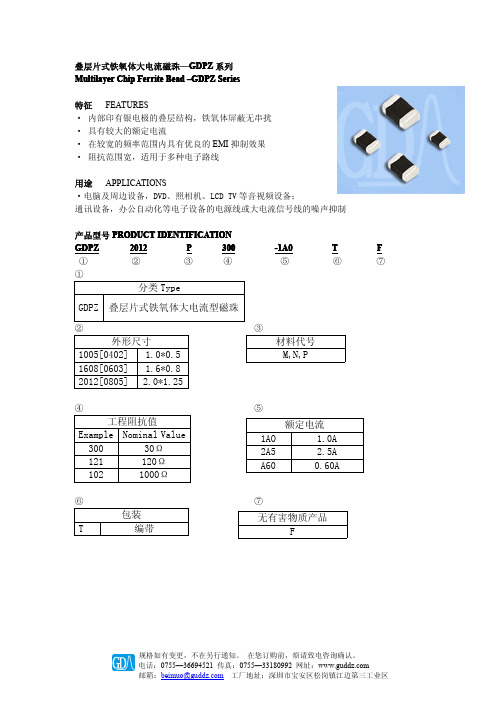
GDPZ2012P300
规格如有变更,不在另行通知。 在您订购前,烦请致电咨询确认。 电话:0755—36694521 传真:0755—33180992 网址: 邮箱:beimuo@ 工厂地址:深圳市宝安区松岗镇江边第三工业区
Max. Rated
Current
额定电流 mA lr 4000 3000 2500 1500 1500 800 800 3000 3000 2500 2000 1500 1000 800
规格如有变更,不在另行通知。 在您订购前,烦请致电咨询确认。 电话:0755—36694521 传真:0755—33180992 网址: 邮箱:beimuo@ 工厂地址:深圳市宝安区松岗镇江边第三工业区
规格如有变更,不在另行通知。 在您订购前,烦请致电咨询确认。 电话:0755—36694521 传真:0755—33180992 网址: 邮箱:beimuo@ 工厂地址:深圳市宝安区松岗镇江边第三工业区
用途 APPLICATIONS ·电脑及周边设备,DVD、照相机、LCD TV 等音视频设备; 通讯设备,办公自动化等电子设备的电源线或大电流信号线的噪声抑制
产品型号 PRODUCT IDENTIFICATION
GDPZ
2012
P
300
①
②
③
④
①
分类 Type
-1A0 ⑤
T
F
⑥
⑦
GDPZ 叠层片式铁氧体大电流型磁珠
GDPZ 2012 TYPE
GZ1005D121TF
Multilayer Chip Ferrite Bead – GZ SeriesOperating Temp. : -55℃~+125℃FEATURES● Internal silver printed layers and magnetic shielded structures to minimize crosstalk●Can be used in a wide range of frequency (from dozens of MHz to hundreds of MHz) to suppress EMI●Three types material and wide range of impedance values for various applicationsAPPLICATIONS●Noise suppression for low speed signal of electric equipments such as computers and peripheral devices, DVD cameras, LCD TVs, communication equipments, OA equipments, etc.PRODUCT IDENTIFICATIONSHAPE AND DIMENSIONS② External Dimensions (L×W) (mm)0603 [0201]0.6×0.3 1005 [0402] 1.0×0.5 1608 [0603] 1.6×0.82012 [0805] 2.0×1.253216 [1206] 3.2×1.6① Type GZChip Ferrite Bead for General Use ③ Material Code D, E, U ⑥ Hazardous Substance Free Products F ⑤ Packing T Tape & Reel Unit: mm [inch] Type L W T a GZ0603[0201]0.6±0.05 [.024±.002] 0.3±0.05 [.012±.002]0.3±0.05 [.012±.002] 0.15±0.05[.006±.002]GZ1005[0402] 1.0±0.15 [.039±.006] 0.5±0.15 [.020±.006]0.5±0.15 [.020±.006] 0.25±0.1 [.010±.004]GZ1608[0603] 1.6±0.15 [.063±.006] 0.8±0.15 [.031±.006]0.8±0.15 [.031±.006] 0.3±0.2 [.012±.008]GZ2012[0805] 2.0 (+0.3, -0.1) [.079 (+.012, -.004)] 1.25±0.2 [.049±.008]0.85±0.2 [.033±.008] 0.5±0.3 [.020±.012]GZ3216[1206] 3.2±0.2 [.126±.008] 1.6±0.2 [.063±.008]0.85±0.2 [.033±.008] 0.5±0.3 [.020±.012]1608② D ③ 121④ T ⑤ F⑥ GZ ①④ Nominal Impedance Example Nominal Value 300 30Ω 121 120Ω102 1000ΩPart Number Impedance Z Test Frequency Max. DC Resistance Max. RatedCurrentThicknessUnits ΩMHz ΩmA mm [inch] Symbol Z Freq. DCR Ir TGZ0603D600TF 60±25% 100 0.40 200GZ0603D800TF 80±25% 100 0.60 200 GZ0603D121TF 120±25% 100 0.80 200 GZ0603D241TF 240±25% 100 1.00 200 GZ0603D601TF 600±25% 100 1.70 2000.3±0.05 [.012±.002]GZ1005 TYPEPart Number Impedance Z Test Frequency Max. DC Resistance Max. RatedCurrentThicknessUnits 单位ΩMHz ΩmA mm [inch] Symbol 符号Z Freq. DCR Ir TGZ1005D100TF 0~15 100 0.05 500GZ1005D310TF 31±25% 100 0.20 300GZ1005D600TF 60±25% 100 0.30 200GZ1005D800TF 80±25% 100 0.35 200GZ1005D121TF 120±25% 100 0.40 200GZ1005D221TF 220±25% 100 0.45 150GZ1005D301TF 300±25% 100 0.50 100GZ1005D421TF 420±25% 100 0.60 100GZ1005D501TF 500±25% 100 0.80 100GZ1005D601TF 600±25% 100 0.90 100GZ1005D751TF 750±25% 100 1.00 100GZ1005D102TF 1000±25% 100 1.20 100GZ1005D152TF 1500±25% 100 1.60 100 GZ1005E800TF 80±25% 100 0.35 200 GZ1005E121TF 120±25% 100 0.40 200 GZ1005E241TF 240±25% 100 0.50 200 GZ1005E601TF 600±25% 100 0.90 100 GZ1005U100TF 0~15 100 0.05 500 GZ1005U300TF 30±25% 100 0.20 300 GZ1005U700TF 70±25% 100 0.30 200 GZ1005U121TF 120±25% 100 0.40 200 GZ1005U221TF 220±25% 100 0.50 100 GZ1005U301TF 300±25% 100 0.60 100 GZ1005U421TF 420±25% 100 0.80 100 GZ1005U601TF 600±25% 100 0.90 100 GZ1005U102TF 1000±25% 100 1.20 1000.5±0.15 [.020±.006]GZ1608 TYPEPart Number Impedance Z Test Frequency Max. DC Resistance Max. RatedCurrentThicknessUnits ΩMHz ΩmA mm [inch] Symbol Z Freq. DCR Ir TGZ1608D110TF 0~15 100 0.05 2000GZ1608D300TF 30±25% 100 0.05 2000GZ1608D600TF 60±25% 100 0.10 500 GZ1608D800TF 80±25% 100 0.15 400 GZ1608D101TF 100±25% 100 0.20 300 GZ1608D121TF 120±25% 100 0.20 3000.8±0.15 [.031±.006]Units ΩMHz ΩmA mm [inch] Symbol Z Freq. DCR Ir TGZ1608D221TF 220±25% 100 0.30 300GZ1608D301TF 300±25% 100 0.35 200GZ1608D471TF 470±25% 100 0.45 200GZ1608D601TF 600±25% 100 0.45 200GZ1608D751TF 750±25% 100 0.50 200GZ1608D102TF 1000±25% 100 0.60 200GZ1608D152TF 1500±25% 100 0.70 150GZ1608D182TF 1800±25% 100 0.90 100GZ1608D202TF 2000±25% 100 1.20 100GZ1608D222TF 2200±25% 100 1.20 100GZ1608E121TF 120±25% 100 0.20 300 GZ1608E181TF 180±25% 100 0.30 300 GZ1608E601TF 600±25% 100 0.45 200 GZ1608E102TF 1000±25% 100 0.60 200 GZ1608U100TF 0~15 100 0.05 2000 GZ1608U300TF 30±25% 100 0.05 2000 GZ1608U600TF 60±25% 100 0.10 500 GZ1608U121TF 120±25% 100 0.20 300 GZ1608U221TF 220±25% 100 0.30 300 GZ1608U301TF 300±25% 100 0.35 200 GZ1608U471TF 470±25% 100 0.40 200 GZ1608U601TF 600±25% 100 0.50 200 GZ1608U102TF 1000±25% 100 0.60 2000.8±0.15 [.031±.006]GZ2012 TYPEPart Number Impedance Z Test Frequency Max.DC Resistance Max.Rated Current Thickness Units ΩMHz ΩmA mm [inch] Symbol Z Freq. DCR Ir T GZ2012D070TF 0~15 100 0.04 2000GZ2012D190TF 19±25% 100 0.04 2000GZ2012D300TF 30±25% 100 0.05 1500GZ2012D800TF 80±25% 100 0.10 1000GZ2012D121TF 120±25% 100 0.15 800GZ2012D181TF 180±25% 100 0.18 700GZ2012D221TF 220±25% 100 0.20 600GZ2012D301TF 300±25% 100 0.20 500GZ2012D421TF 420±25% 100 0.30 500GZ2012D501TF 500±25% 100 0.30 500 GZ2012D601TF 600±25% 100 0.30 500 GZ2012D751TF 750±25% 100 0.35 500 GZ2012D102TF 1000±25% 100 0.35 500 GZ2012D152TF 1500±25% 100 0.40 500 GZ2012D202TF 2000±25% 100 0.50 500 GZ2012E800TF 80±25% 100 0.10 1000 GZ2012E181TF 180±25% 100 0.20 600 GZ2012E301TF 300±25% 100 0.20 500 GZ2012E501TF 500±25% 100 0.30 500 GZ2012E601TF 600±25% 100 0.30 5000.85±0.2 [.033±.008]Units ΩMHz ΩmA mm [inch] Symbol Z Freq. DCR Ir TGZ2012E102TF 1000±25% 100 0.35 500GZ2012U100TF 0~15 100 0.04 2200GZ2012U170TF 17±25% 100 0.04 2000GZ2012U300TF 30±25% 100 0.05 1500GZ2012U700TF 70±25% 100 0.10 1000 GZ2012U121TF 120±25% 100 0.15 800 GZ2012U221TF 220±25% 100 0.20 600 GZ2012U301TF 300±25% 100 0.20 500 GZ2012U421TF 420±25% 100 0.25 500 GZ2012U601TF 600±25% 100 0.30 500 GZ2012U102TF 1000±25% 100 0.40 5000.85±0.2 [.033±.008]GZ3216 TYPEPart Number Impedance Z Test Frequency Max.DC Resistance Max.Rated Current Thickness Units ΩMHz ΩmA mm [inch] Symbol Z Freq. DCR Ir TGZ3216D000TF 0~15 100 0.03 2200GZ3216D310TF 31±25% 100 0.05 2000GZ3216D600TF 60±25% 100 0.10 1000GZ3216D800TF 80±25% 100 0.10 1000GZ3216D121TF 120±25% 100 0.10 1000GZ3216D221TF 220±25% 100 0.20 600 GZ3216D301TF 300±25% 100 0.20 600 GZ3216D501TF 500±25% 100 0.30 600 GZ3216D601TF 600±25% 100 0.30 600 GZ3216D102TF 1000±25% 100 0.60 500 GZ3216D122TF 1200±25% 100 0.60 300 GZ3216U601TF 600±25% 100 0.30 6000.85±0.2 [.033±.008]:※Products with other electrical characteristics can be provided upon customer’s request. Please contact your local sales.DETAIL ELECTRICAL CHARACTERISTICSGZ0603 TYPEGZ1005 TYPEFrequency(MHz)I m p e d a n c e (Ω)Frequency(MHz)I m p e d a n c e (Ω)GZ0603D601TFFrequency(MHz)I m p e d a n c e (Ω)GZ0603D600TFFrequency(MHz)I m p e d a n c e (Ω)Frequency(MHz)I m p e d a n c e (Ω)GZ0603D800TFFrequency(MHz)I m p e d a n c e (Ω)GZ1005D800TFFrequency(MHz)I m p e d a n c e (Ω)GZ1005D301TFFrequency(MHz)I m p e d a n c e (Ω)GZ1005D421TFFrequency(MHz)I m p e d a n c e (Ω)GZ1005D501TFFrequency(MHz)I m p e d a n c e (Ω)GZ1005D751TFFrequency(MHz)I m p e d a n c e (Ω)GZ1005D102TFFrequency(MHz)I m p e d a n c e (Ω)GZ1005D601TFFrequency(MHz)I m p e d a n c e (Ω)GZ1005D100TFFrequency(MHz)I m p e d a n c e (Ω)GZ1005D310TFFrequency(MHz)I m p e d a n c e (Ω)GZ1005D600TFFrequency(MHz)I m p e d a n c e (Ω)GZ1005D121TFFrequency(MHz)I m p e d a n c e (Ω)GZ1005D221TFFrequency(MHz)I m p e d a n c e (Ω)GZ1005D152TFFrequency(MHz)I m p e d a n c e (Ω)GZ1005E241TFFrequency(MHz)I m p e d a n c e (Ω)GZ1005E601TFFrequency(MHz)I m p e d a n c e (Ω)Frequency(MHz)I m p e d a n c e (Ω)GZ1005E800TFFrequency(MHz)I m p e d a n c e (Ω)Frequency(MHz)I m p e d a n c e (Ω)GZ1005U300TFFrequency(MHz)I m p e d a n c e (Ω)Frequency(MHz)I m p e d a n c e (Ω)Frequency(MHz)I m p e d a n c e (Ω)GZ1005U221TFFrequency(MHz)I m p e d a n c e (Ω)GZ1005U301TFFrequency(MHz)I m p e d a n c e (Ω)GZ1005U601TFFrequency(MHz)I m p e d a n c e (Ω)GZ1005U102TFFrequency(MHz)I m p e d a n c e (Ω)GZ1005U421TFFrequency(MHz)I m p e d a n c e (Ω)GZ1608D110TFFrequency(MHz)I m p e d a n c e (Ω)Frequency(MHz)I m p e d a n c e (Ω)GZ1608D600TFFrequency(MHz)I m p e d a n c e (Ω)GZ1608D800TFFrequency(MHz)I m p e d a n c e (Ω)Frequency(MHz)I m p e d a n c e (Ω)GZ1608D121TFFrequency(MHz)I m p e d a n c e (Ω)Frequency(MHz)I m p e d a n c e (Ω)Frequency(MHz)I m p e d a n c e (Ω)Frequency(MHz)I m p e d a n c e (Ω)GZ1608D601TFFrequency(MHz)I m p e d a n c e (Ω)GZ1608D751TFFrequency(MHz)I m p e d a n c e (Ω)GZ1608D102TFFrequency(MHz)I m p e d a n c e (Ω)Frequency(MHz)I m p e d a n c e (Ω)GZ1608D182TFFrequency(MHz)I m p e d a n c e (Ω)GZ1608D202TFDETAIL ELECTRICAL CHARACTERISTICSGZ1608 TYPEFrequency(MHz)Frequency(MHz)I m p e d a n c e (Ω)Frequency(MHz)I m p e d a n c e (Ω)Frequency(MHz)I m p e d a n c e (Ω)GZ1608U121TFFrequency(MHz)I m p e d a n c e (Ω)GZ1608U301TFFrequency(MHz)I m p e d a n c e (Ω)GZ1608U471TFFrequency(MHz)I m p e d a n c e (Ω)Frequency(MHz)I m p e d a n c e (Ω)GZ1608U102TFFrequency(MHz)I m p e d a n c e (Ω)GZ1608U221TFFrequency(MHz)I m p e d a n c e (Ω)GZ1608U100TFFrequency(MHz)I m p e d a n c e (Ω)GZ1608E102TFFrequency(MHz)I m p e d a n c e (Ω)Frequency(MHz)I m p e d a n c e (Ω)Frequency(MHz)I m p e d a n c e (Ω)GZ2012D070TFFrequency(MHz)I m p e d a n c e (Ω)GZ2012D190TFFrequency(MHz)I m p e d a n c e (Ω)GZ2012D300TFFrequency(MHz)I m p e d a n c e (Ω)GZ2012D800TFFrequency(MHz)I m p e d a n c e (Ω)GZ2012D121TFFrequency(MHz)I m p e d a n c e (Ω)GZ2012D221TFFrequency(MHz)I m p e d a n c e (Ω)GZ2012D301TFFrequency(MHz)I m p e d a n c e (Ω)GZ2012D421TFFrequency(MHz)I m p e d a n c e (Ω)GZ2012D501TFFrequency(MHz)I m p e d a n c e (Ω)GZ2012D751TFFrequency(MHz)I m p e d a n c e (Ω)GZ2012D102TFFrequency(MHz)I m p e d a n c e (Ω)GZ2012D152TFFrequency(MHz)I m p e d a n c e (Ω)GZ2012D202TFFrequency(MHz)I m p e d a n c e (Ω)GZ2012D601TFFrequency(MHz)I m p e d a n c e (Ω)GZ2012D181TFFrequency(MHz)I m p e d a n c e (Ω)GZ2012E800TFFrequency(MHz)I m p e d a n c e (Ω)GZ2012E102TFFrequency(MHz)I m p e d a n c e (Ω)GZ2012U100TFFrequency(MHz)I m p e d a n c e (Ω)GZ2012U300TFFrequency(MHz)I m p e d a n c e (Ω)GZ2012U700TFFrequency(MHz)I m p e d a n c e (Ω)GZ2012U121TFFrequency(MHz)I m p e d a n c e (Ω)GZ2012U301TFFrequency(MHz)I m p e d a n c e (Ω)GZ2012U601TFFrequency(MHz)I m p e d a n c e (Ω)GZ2012U170TFFrequency(MHz)I m p e d a n c e (Ω)GZ2012U221TFFrequency(MHz)I m p e d a n c e (Ω)GZ2012U421TFFrequency(MHz)I m p e d a n c e (Ω)GZ2012E181TFFrequency(MHz)I m p e d a n c e (Ω)GZ2012E301TFFrequency(MHz)I m p e d a n c e (Ω)GZ2012E501TFFrequency(MHz)I m p e d a n c e (Ω)GZ2012E601TFSpecifications subject to change without notice. Please check our website for latest information. Revised 2014/04/15Sunlord Industrial Park, Dafuyuan Industrial Zone, Guanlan, Shenzhen, China 518110 Tel : 0086-755-29832660 Fax : 0086-755-82269029 E-Mail : sunlord@Sunlord电气特性 DETAIL ELECTRICAL CHARACTERISTICSGZ2012 TYPEGZ3216 TYPEFrequency(MHz)I m p e d a n c e (Ω)GZ2012U102TFFrequency(MHz)I m p e d a n c e (Ω)GZ3216D600TFFrequency(MHz)I m p e d a n c e (Ω)Frequency(MHz)I m p e d a n c e (Ω)Frequency(MHz)I m p e d a n c e (Ω)GZ3216D301TFFrequency(MHz)I m p e d a n c e (Ω)GZ3216D601TFFrequency(MHz)I m p e d a n c e (Ω)GZ3216D310TFFrequency(MHz)I m p e d a n c e (Ω)GZ3216D800TFFrequency(MHz)I m p e d a n c e (Ω)GZ3216U601TFFrequency(MHz)I m p e d a n c e (Ω)GZ3216D102TFFrequency(MHz)I m p e d a n c e (Ω)Frequency(MHz)I m p e d a n c e (Ω)GZ3216D000TFFrequency(MHz)I m p e d a n c e (Ω)GZ3216D501TF。
PBY201209T-301Y-N叠层片式铁氧体磁珠规格书
Electrical Characteristics
Part Number PBY100505T-100Y-N PBY100505T-300Y-N PBY100505T-600Y-N PBY100505T-800Y-N PBY100505T-121Y-N PBY100505T-151Y-N PBY100505T-221Y-N PBY100505T-601Y-N PBY100505T-102Y-N Impedance (Ω±25%) 10 30 60 80 120 150 220 600 1000 Test Frequency (MHz) 100 100 100 100 100 100 100 100 100 RDC (Ω) Max 0.03 0.05 0.075 0.09 0.09 0.14 0.18 0.34 0.49 Rated current (mA) Max 2000 1700 1500 1200 1400 1400 1100 700 500
IMPEDANCE(Ω)
14 12 10 8 6 4 2 0 1 10
Z
30 25 20 15 10 5 0
Z
Z X R
1 10 100 1000
X R
FREQUENCY (MHz) RDC<0.05 Ω Rated Current :1000 mA
100 1000
X R
1 10 100 1000
FREQUENCY (MHz) RDC<0.065 Ω Rated Current :1000 mA
Note: When ordering, please specify tolerance code. Tolerance : Y=±25% Operating temperature range-55℃~125℃(Including self - temperature rise) Rate Current:Applied the current to coils, the temperature rise shall not be more than 30℃ Measure Equipment: Z:HP4291A RDC:HP4338B or CHEN HWA 502
电感培训资料
功率电感
磁珠名称的说明
片式磁珠是片感的一种,其制作工艺和片感完全相同。
片式磁珠主要用于消除存在于传输线路中的高频噪声。习惯上把EMI应 用的片感称为磁珠,而把用于信号处理的称为片感。
磁珠名称的来由
噪声抑制电路 穿芯磁珠 Bead 穿芯电容
穿芯磁珠
珠
贴片电容
贴片电感
Ferrite Bead
翻译成磁珠
被动元件主要原理及应用
二、片式电感的分类
按制作工艺
1. 叠层片式电感
2. 绕线式片感
按应用
EMI应用、旁通 、扼流等电路 片式磁珠 (叠层片式电感)
1.抑制干扰讯号
2.讯号处理
3.电源管理
滤波、谐振、 耦合等电路
大电流、大功率下应用
( 绕线式片感)
片式电感 (叠层片式电感、绕线式片感)
Frequency(Hz)
Fr
d、通用磁珠(STGB系列)
STGB2012-471
|Z|&R&XL()
800
TEST EQUIPMENT:HP4291B
600
400
|Z|
200
R
0 1M
XL
10M
100M
1G
1.8G
Frequency(Hz)
e、尖峰磁珠(STSB系列)
STSB3216-201
这里特别介绍叠层片式电感器/磁珠内部线圈是 如何实现连通的:
六、产品的标识方法
STLI 2012 — 150 K
(1) (2) (3)
T
(4) (5)
(1)产品系列
系列代码
STLI STMI STHI STGB STPB STSB
超大电流型贴片磁珠(CBM)
0.01 0.01 0.01 0.01 0.03 0.03 0.04 0.05 0.08 0.08 0.08 0.08 0.10 0.10 0.12 0.12 0.20 0.30
55
【 南京南山半导体有限公司 — 风华高科磁珠选型资料】
FERRITE CHIP BEADS
10
100
1000
1000
1000
1
10 100 Frequency [MHz]
1000
1608 SERIES
CBM160808U070T
CBM160808U190T
100
CBM160808U300T
50 40 30 20 10 0 1 10 100 Frequency[MHZ]
Z
50
]
]
40
Impedance[
APPLICATIONS
Digital videos communication equipment OA equipment and others.
ORDERING CODE
CBM 201209 U 121 T
L W T) Product Code (mm) Dimensions U CBM MULTILAYER CHIP POWER BEADS 100505 160808 201209 321609 322513 451616 453215 1.0 0.5 0.5 1.6 0.8 0.8 2.0 1.2 0.9 3.2 1.6 0.9 3.2 2.5 1.3 4.5 1.6 1.6 4.5 3.2 1.5 Example 110 300 102 Material Code
53
【 南京南山半导体有限公司 — 风华高科磁珠选型资料】
- 1、下载文档前请自行甄别文档内容的完整性,平台不提供额外的编辑、内容补充、找答案等附加服务。
- 2、"仅部分预览"的文档,不可在线预览部分如存在完整性等问题,可反馈申请退款(可完整预览的文档不适用该条件!)。
- 3、如文档侵犯您的权益,请联系客服反馈,我们会尽快为您处理(人工客服工作时间:9:00-18:30)。
MCL2520 [1008]
2.5±0.2 [.098±.008]
2.0(+0.3, -0.1)
0.9±0.1
[.079(+.012, -.004)] [.035±.004]
0.5±0.3 [.020±.012]
Sunlord
The Specifications subject to change without notice. Please check our website for latest information. Revised 2016/07/15
Sunlord Industrial Park, Dafuyuan Industrial Zone, Guanlan, Shenzhen, China 518110 Tel: 0086-755-29832660 Fax: 0086-755-82269029 E-Mail: sunlord@
Heat Rating Current Max.
mA Irms 1300 850
Heat Rating Current Max.
mA Irms 1100 850
Heat Rating Current Max.
mA Irms 1400 950
Sunlord
The Specifications subject to change without notice. Please check our website for latest information. Revised 2016/07/15
SPECIFICATIONS
MCL2012A TYPE
Part Number
Inductance
L Test Freq. DC Resistance L
Min. Selfresonant Frequency
Saturation Current Typ.
Units Symbol MCL2012A2R2MT MCL2012A4R7MT
Sunlord Industrial Park, Dafuyuan Industrial Zone, Guanlan, Shenzhen, China 518110 Tel: 0086-755-29832660 Fax: 0086-755-82269029 E-Mail: sunlord@
MHz S.R.F
120 70
Min. Selfresonant Frequency
mA Isat 900 600
Saturation Current Typ.
Units
μH
MHz
Ω
MHz
mA
Symbol
L
Freq.
DCR
S.R.F
Isat
MCL2520A2R2MT
2.2
1
0.13±25%
70
500
APPLICATIONS
DC-DC converter circuits for mobile phones, wearable devices, DVCs, HDDs, etc.
PRODUCT IDENTIFICATION
MCL
2012
A
2R2
M
①
②
①
Type
MCL
Chip Inductor for Choke
Saturation Current Typ.
Units Symbol MCL2016A1R0MT MCL2016A2R2MT
MCL2520A TYPE
Part Number
μH L 1.0 2.2
Inductance
MHz
Freq. 1 1
Ω
DCR 0.14±25% 0.22±25%
L Test Freq. DC Resistance L
④
Nominal Inductance
Example
Nominal Value
2R2
2.2μH
③
④
②
External Dimensions (L×W) (mm)
2012 [0805]
2.0×1.25
2016 [0806] 2520 [1008]
2.0×1.6 2.5×2.0
⑤ ③
A
⑤
⑥
Inductance Tolerance
Multilayer Chip Inductor for Choke – MCL-A Series
Operating Temp. : -40℃~+85℃
FEATURES
● Monolithic structure for high reliability ● Excellent solderability and high heat resistance ● No cross coupling due to magnetic shield ● High DC bias current due to developed material ● Low DC resistance
[0806] [.079 (+.012, -.004)]
W
1.25±0.2 [.049±.008]
1.6±0.2 [.063±.008]
Unit: mm [inch]
T
a
0.85±0.2 [.033±.008]
0.5±0.3 [.020±.012]
0.9±0.1 [.035±.004]
0.5±0.3 [.020±.012]
MCL2016A TYPE
Part Number
μH L 2.2 4.7
Inductance
MHz
Freq. 1 1
Ω
DCR 0.18±25% 0.30±25%
L Test Freq. DC Resistance L
MHz S.R.F
50 60
Min. Selfresonant Frequency
mA Isat 300 180
MCL2520A4R7MT
4.7
1
0.28±25%
45
250
※Rated current: Isat or Irms, whichever is smaller;
※Isat: DC current at which the inductance drops approximate 30% from its value without current; ※Irms : DC current that causes the temperature rise (△T =40°C) from 20°C ambient.
M
±20%
T
T
⑥
Feature Type Inner Code
Packing Tape & Reel
SHAPE AND DIMENSIONS
Type
MCL2012 [0805]
L
2.0 (+0.3, -0.1) [.079 (+.012, -.004)]
MCL2016
2.0 (+0.3, -0.1)