日本共立4105A接地电阻测试仪中文说明书
4102、4102A、4105接地电阻测试仪检测及降阻方法
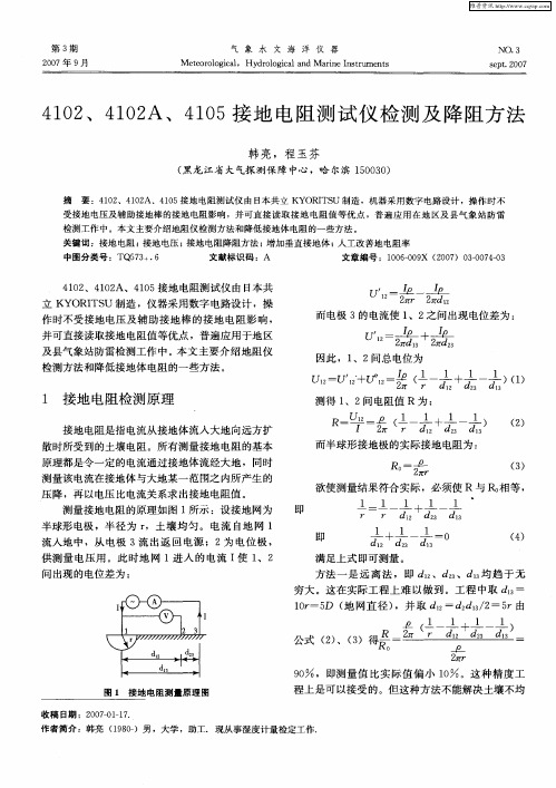
1 接地 电 阻检 测 原 理
接地 电阻是 指 电流从 接地体 流人 大地 向远 方扩
散 时所 受 到 的土壤 电阻 。所 有测 量接 地 电阻 的基本 原理都 是令 一定 的 电流通过 接地 体流 经大 地 ,同时 测量该 电流在接地 体 与大地 某一 范 围之 内所 产 生 的
测得 1 、2间 电阻值 R 为 :
R U -P ( 一 1 一 ) ( - ̄ _ 十1 2 2 1 )
而半 球形 接地 极 的实际 接地 电阻 为 :
Ro 卫 r 2r r
() 3
压 降 ,再 以 电压 比电流关 系求 出接地 电阻值 。
测 量接 地 电阻 的原理如 图 1所示 :设 接地 网为
受接地电压及辅助接地棒的接地 电阻影响 ,并可直接读 取接地 电阻值等优 点 ,普遍应 用在地 区及县气 象站 防雷
检测工作中 。本文主要介绍地阻仪检测方法和降低接地体 电阻 的一些方法 。
关键词 :接地 电阻 ; 接地 电压 ;接地 电阻降阻方法 ; 增加垂直接地体 ; 人工改善地 电阻率 中图分类号 :T 7 +. Q5 3 6 文献标识码 :A 文章编号 :1 0一0 X (0 7 30 7—3 0 6O 9 2 0 )0~0 40
接地电阻测试仪简单使用说明书
接地电阻测试仪简单使用说明书
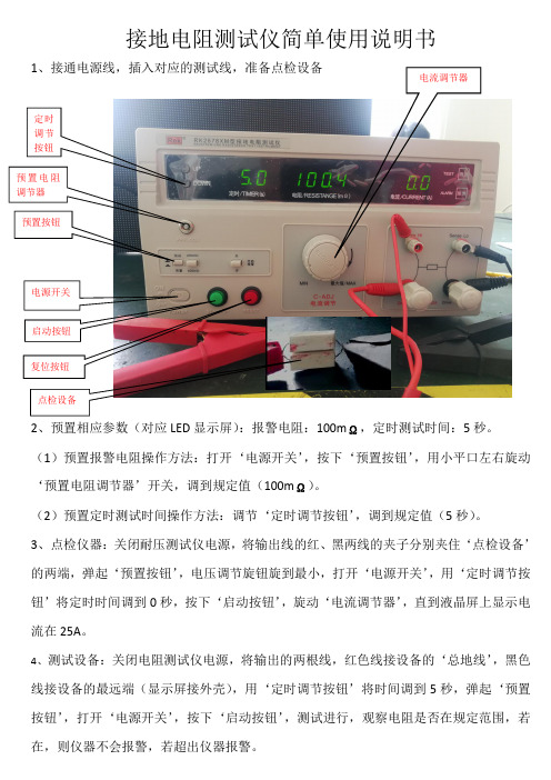
1、接通电源线,插入对应的测试线,准备点检设备
2、预置相应参数(对应LED 显示屏):报警电阻:100m Ω,定时测试时间:5秒。
(1)预置报警电阻操作方法:打开‘电源开关’,按下‘预置按钮’,用小平口左右旋动‘预置电阻调节器’开关,调到规定值(100m Ω)。
(2)预置定时测试时间操作方法:调节‘定时调节按钮’,调到规定值(5秒)。
3、点检仪器:关闭耐压测试仪电源,将输出线的红、黑两线的夹子分别夹住‘点检设备’的两端,弹起‘预置按钮’,电压调节旋钮旋到最小,打开‘电源开关’,用‘定时调节按钮’将定时时间调到0秒,按下‘启动按钮’,旋动‘电流调节器’,直到液晶屏上显示电流在25A 。
4、测试设备:关闭电阻测试仪电源,将输出的两根线,红色线接设备的‘总地线’,黑色线接设备的最远端(显示屏接外壳),用‘定时调节按钮’将时间调到5秒,弹起‘预置按钮’,打开‘电源开关’,按下‘启动按钮’,测试进行,观察电阻是否在规定范围,若在,则仪器不会报警,若超出仪器报警。
电流调节器
定时
调节
按钮
预置电阻
调节器
预置按钮 电源开关
启动按钮
复位按钮
点检设备
5、。
4102A接地电阻测试仪使用
4102A/4105A 接地电阻测试仪使用
• 测试仪部件名称
• • • • • • • • LCD显示屏幕 电池更换标志 调试LED指示灯(绿色) 测试按钮 测试端子 测试线(MODEL7095) 辅助接地棒(MODEL8032) 简易测试线(MODEL7094)
仪器使用
• 准备测试
• 电池电压检查:
2、通路测试
• • • 测量程序同接地电阻测量, 待测电阻<40Ω时会发出 哗哗声音。
3、接地系统漏电流测量
• 开机,将圆形开关置 于mA或A档位; • 夹住待测电极、接地 棒; • 从显示器上读取电流 值。
二、注意事项 • 1、即使仪器设备使用得当且已有接地措 施,也建仪戴橡皮手套操作,以确保安 全。 • 2、在测试之前,应将连接在电气设备上 的金属物或线视为有致命的危险,接地 系统也无例外,因此在电气设备中使用 本表时,应格外注意安全。 • 3、若接地棒上出现超过3A电流或30V电 压时,显示器上将显示NOISE的字样, 此时处于干扰下的测量将不准确。
•
• • •
打开仪器 电力充足,显示幕上没有显示电池符号,若显示屏闪烁或出现电池符号, 示电量不足,应更换电池 测量种类: 常规接地电阻测量法 简易接地电阻测量法
常规接地电阻测量
• • • • • 1、测试线的连接: 如左图将辅助接地棒P及C以直线相距间隔5至10米处打入地下,连接绿 色线至仪器端子E,黄色导线至端子P及红色导线至端子C。 注意: 辅助接地棒应插在含水量高的土地上,遇干地,砂地或含碎石地时,须 加水以保持接地棒打入处的潮湿 遇水泥地时,将接地棒平放加水,并将湿毛巾等覆于接地棒上再测量。
接地极的布置接地极的布置
• 直线排列时,Sy=20m, S1=40m。 • 扇形排列时: • Sy=S1=20m,其夹角以29度为 宜。 • 当接地体构成网络时,Sy应大式地阻仪相比具有以下特点:
MODEL4105A接地电阻测试仪资料

MODEL 4105A 接地电阻测试仪1.安全事项为确保安全,以下的注意事项请务必遵守:(1) 测试前请先确认量程选择开关已设定在适当档位。
(2) 测试导线的连接插头已紧密插入端子内。
(3) 主机潮湿状态下,请勿接线。
(4) 各档位中,请勿加载超于该量程额定值的电量。
(5) 当与被测物在线连接时,请勿切换量程选择开关。
(6) 测试端子间请勿加载超过200安培的交流或直流电压。
(7) 请勿在易燃性场所测试,火花可能会引起爆炸。
(8) 若仪器出现破损或测试导线发生龟裂而造成金属外露等异常情况时,请停止使用。
(9) 更换电池,请务必确定测试导线已从测试端子拆除。
(10)主机潮湿状态下请勿更换电池。
(11)使用后请务必将量程选择开关切于OFF位置。
(12)请勿于高温潮湿,有结露的场所及日光直射下长时间放置。
(13)本测试器请勿存放于超过60℃之场所。
(14)长时间不使用,请取出电池后保存。
(15)主机潮湿时,请干燥后保存。
2. 特点本仪器是用来测定配电线,屋内配线,电机机电设备等接地阻抗测试仪。
此外,还有测量接地电压用的交流电压档可使用。
● 根据IEC 60529(IP54)标准设计、制造、测试,可于恶劣气候下工作。
● 4105A使用大型数字式LCD显示屏,4102A是指针盘显示测量值,方便读取。
● 附有携带方便的携带包,所有附件均可置于其内。
● 测量接地电阻,辅助接地电阻不适于过大场合,此种情况发生时会自动检查并显示警告信息。
● 可使用简易测试导线作简易测试。
3. 部件名称4. 准备测试4-1 电池电压检查开机后,若显示屏没显示电池符号,则表示目前电力充足,若显示屏闪烁或出现此标志时,请依照第七章说明更换电池。
4-2 测试线连接测量前请确保测试导线插头已完全插入测试端。
若连接不紧密将导致测量结果出现误差。
5. 测试方法危险:测量接地电阻时,E-C或E-P的端子间会产生最大50V的交流电压,请勿接触测试导线以免触电。
4105A-H接地电阻测试仪

4105A-H接地电阻测试仪简介4105A-H接地电阻测试仪是一种用于测量接地系统电阻值或接地系统接触电阻值的测试仪器。
接地系统是指在电路中与地相连的所有导体和接地设备以及与其相连的线路、设备和电气装置。
在电气系统中,接地是为了确保安全性和稳定性而进行的一项必要操作。
在电气系统中使用接地时,需要测量接地系统的电阻值,以便在需要时进行维护和保养。
原理4105A-H接地电阻测试仪采用了恒流源的测量原理。
测量时,测试仪通过恒流源向接地系统注入恒定的电流,然后测量系统的电压降,并计算出接地系统的电阻值。
特点4105A-H接地电阻测试仪具有以下特点:•数字显示:测试结果以数字形式直接显示在测试仪器面板上;•自动校准:测试仪具有自动校准功能,可以在不同温度、湿度和供电电压等条件下自动校准;•高精度:测试仪具有高精度的测量模块和软件算法,能够测量出很小的电阻值;•轻便易用:测试仪器体积小,重量轻,易于携带和操作。
应用4105A-H接地电阻测试仪可用于以下领域:•电力行业:用于电力变电站、电网、发电厂等的接地电阻测试;•建筑行业:用于建筑物、电梯、管道等的接地电阻测试;•医疗行业:用于医疗设备、手术室等的接地电阻测试;•航空航天行业:用于飞机、飞船等的接地电阻测试。
操作步骤使用4105A-H接地电阻测试仪进行接地电阻测试的操作步骤如下:1.将测试仪和被测试接地系统连接。
测试仪的一端连接接地系统,另一端连接测试仪器的电源口。
2.打开测试仪器,进行自检。
3.选择用于测试的电流大小和测试模式(自动或手动)。
4.等待测试仪进行测试,测试完成后,读取测试结果。
5.清理测试仪器并关闭电源。
维护和保养使用4105A-H接地电阻测试仪时,需要进行以下维护和保养:1.定期进行外部清洁,避免灰尘和污垢积累;2.在测试后及时清理测试仪器,避免因长时间存放而导致零件老化;3.保持测试仪器干燥,避免水分和潮气对测试仪器的影响;4.定期进行校准和维修,以保证测试仪器的准确性和可靠性。
胜利4105A接地仪表使用手册英文
Instruction Manual for Digital Grounding Resistance MeterInstruction Manual for DigitalGrounding Resistance MeterTable of ContentsI. Overview (2)II. Open-case Inspection (3)III. Safety Precautions (4)IV. Work Principle (7)V. Appearance Description (9)VI. Technical Characteristics (10)VII. Resistance Measurement Method..12 VIII.Battery Installation (20)IX.Troubleshooting (22)WarningThe warnings and safety requirements stated in this manual must be strictly observed to ensure safety. Please read the operating instructions carefully before using this meter.I.OverviewGrounding Resistance Meter, as a professional instrument for measurement of grounding resistance of electrical equipment, is made by improving the circuit, structure and technology of traditional ground resistance meter. Witha beautiful and practical fashion style, this meter will provide more complete function, higher accuracy and more convenient operation. Thanks to the dust-and-moisture proof structure, this meter is better suited to field operation. It is designed to measure the grounding resistance of grounding systems of a variety of power systems, electrical equipment and lightning protection equipment, and also to measure AC voltage.II.Open-case Inspection1.Grounding resistance meter1 set2.Canvas bag1 Pcs3.Ground drill rod2 Pcs4.Auxiliary testing wire1 set(including: a piece of 15-meter redwire, 10-meter yellow wire, and5-meter green wire)5.Simple testing wire1 set(including: a piece of 1.6-meter red wire and 1.6-meter green wire)6.5# alkaline battery (LR 6 AA) (1.5V)x 8 8 Pcs7.Instruction manual1 copy8.Strap1 pieceIII.Safety Precautions1. Please read this instruction manual carefully before using this grounding resistance meter2. Do not use the grounding resistance meter and measuring wire with damaged surface.3. Do not touch the conductor with a voltage of higher than DC 60V or AC36V RMS in order to prevent electric shock, since the said voltage has reached the standard of electric shock.4. Before the measurement of resistance, the tester must be completely isolatedwith power circuit in order to ensure accurate readings and personal safety.5. The meter shall not be stored at high temperature; direct sunlight shall be avoided so as not to affect the service life of LCD.6. When the symbol "" which indicates "low battery" appears, the battery shall be replaced. Before long-term storage, the batteries shall be taken out to prevent the damage to meter caused by battery leakage.7. Special care should be exercised during the measurement for bare wires. 8. The battery will be disconnected when an external adapter is used. In this case,the battery cannot be recharged. Note: please select the power supply mode () .9. Grounding resistance testing requirements:a. The AC grounding resistance shall not be greater than 4Ω;b. The safety grounding resistance shall not be greater than 4Ω;c. The DC grounding resistance shall be determined according to specific requirements of computer system;d. Lightning protection grounding resistance shall not be greater than 10Ω;e. For the joint grounding of shielding system, the grounding resistance shall not be greater than 1Ω;Warning!ResistanceHighVoltage!Dangerous!ACEarth Battery under-voltageDoubleinsulation CE compliedIV.Work PrincipleThe measuring principle of grounding resistance is based on the law of resistance. Insert 4 electrodes (E1, P1, P2, E2) to a certain depth under the ground, and the distance between electrodes shallbe around 20 meters. See the figure below:AC signals act on electrodes E1 and E2, and the current that flows through the earth shall be measured by ammeter through electrodes P1 and P2. If the current value is a constant, the measured voltage will be proportional to earth resistance. The displayed value depends on swamping resistance; hence, the appropriate range shall be determined according to measured resistance valuesin order to get the best readings. AC signal is generated by the built-in converter.V.Appearance Description1, 2, 3 and 4: Range selector switch (2 0Ω/200Ω/2000Ω/EARTH VOLTAGE). 5: Digital holding switch (HOLD)6: Power Switch: self-locking power switch (POWER)7: Testing indicator: this lamp goes on during the testing if the connection iscorrect.8: Test button.9: LCD: display measurement data and unit symbols.10: Instrument model11: P port: potential pole.12: C port: current pole.13: E port: grounding pole.14: ACV port: voltage pole.15: Power adapter jack ().VI.Technical Characteristics1. General features(1) Display: 84.8 ×59.8mmwindow-type LCD display;Maximum displayed value "1999".(2) Over-range indication: the firstdigit is "1" when the upper limit isexceeded.(3) Power supply: 5# alkaline batteryLR6 (1.5V) x 8 (can be connected tooptional adapter); under-voltageindication function is provided.(4)Power consumption:powerconsumption during no-load testing is≤800mw.(5) Operating environment: 0℃- 4 0℃.Relative humidity: 30% - 85%RH. (6) Overall dimensions: 175(L)×110(W)×70(D)mm(7)Weight: about 680g (includingbatteries).2. Technical data Grounding resistanceMeasuring rangeBasicaccuracyResolution20Ω ±(2%+0.1Ω)0.01Ω 200Ω 0.1Ω2000Ω ±(2%+3d)1ΩGrounding voltage (50Hz - 200Hz)Measuring range Basic accuracy Resolution InputimpedanceOverloadprotection200 V ±( 2.0 % + 6 d ) 0.1 V 1 MΩ 200V rms VII.Resistance Measurement Method7-1. Battery voltage inspectionAfter the startup, if the battery symbol is not indicated on the display, it means that the current power is sufficient. When the display flashes or shows this symbol, please replace the battery in accordance with instructions in Chapter VIII.7-2. Testing wire connectionPlease make sure the plug of testing lead has been completely inserted into the test side. The loose connection may lead to errors in the measurement results.7-3 Test methodDanger: an AC voltage of up to 50Vmay occur between E-C or E-P terminals during the measurement of grounding resistance. Do not touch test lead so as to avoid electric shock.7-3-1Conventional resistance measurement method1) Test lead connectionAs shown below, insert the auxiliary grounding rods P and C into the ground vertically at the point 5-10 meters from the grounded object, connect the green wire to instrument terminal E, the yellow one to terminal P, and the red one to terminal C.Note: Please insert the auxiliary grounding rod into the ground with highwater content. If the rod is to be inserted into dry ground, silica-containing ground or the ground with gravels, the ground shall be wetted with water in order to ensure that the grounding rod be inserted into wet ground. In case of cement ground, please apply water to the horizontally placed grounding rod, and cover it with wet towel before the measurement.2) Grounding voltage measurement Please set the range selector switch toEarth Voltage position. If the voltage value is displayed on the screen, it means there is grounding voltage in the system. Please check if the voltage value is lower than 10V. If the value is above 10V, an error of measured grounding resistance value may occur. In this case, please turn off the power supply of tested grounding device, and carry out the measurement after the grounding voltage drops.3) Grounding resistance measurement Start from the 2000Ωlevel, and press the "TEST" key. Backlight goes on to indicate that a test is in progress. If the displayed value is too small, you can change the level to 200Ω, 20Ω.... The displayed value under this circumstanceis the measured value of grounding resistance.Note: The symbol "" means the grounding impedance of auxiliary grounding rod C is too high. In this case, please check if the connection is loose, or increase the humidity of ground around the auxiliary grounding rod to reduce ground impedance.Note: Ensure that the wires are not entwined. If the testing wires are entwined with each other, the mutual induction may occur during the testing in "false connection" condition and will influence the readings. If the auxiliarygrounding impedance is too strong, an error of display value may occur. Ensure that the auxiliary grounding rods P and C are inserted into wet ground, and all the connection parts are in full contact.7-3-2. Simple grounding resistance measurement methodThis is a simple method for the places where insertion of auxiliary grounding rod is not available. For this method, a grounding electrode like metal water pipe, commercial electric power system common grounding terminal or structure grounding terminal, etc. with extremely weak grounding impedance is used instead of auxiliary grounding rods C and P. Please use simple test leads.1) Test lead connectionPlease connect the leads according to the figure below.Note: If the simple test leads supplied together with this instrument are not used, please make a short circuit for terminals C and P.2) Grounding voltage measurement Please set the range selector switch toEarth Voltage position. If the voltage value is displayed on the screen, it means there is grounding voltage in the system. Please check if the voltage value is lower than 10V. If the value is above 10V, an error of measured grounding resistance value may occur. In this case, please turn off the power supply of tested grounding device, and carry out the measurement after the grounding voltage drops.3) Grounding resistance measurement Start from the 2000Ωlevel. Please press the "TEST" button. The backlight goes on to indicate a test is in progress. If the displayed value is too small, please switch to the 200Ω/20Ωlevel. The value displayed in this case is thegrounding resistance value. Please turn off the power switch after the test is completed in order to save power. Note: ●The measured current is about 2mA. The circuit breaker will not be actuated even if a leakage circuit breaker is connected.●The real grounding resistancevalue RX is subject to thefollowing formula:RX = RE - rere: grounding resistance ofcommon ground terminal ofcommercial power systemetc.Re: instrument groundingresistance readingVIII.Battery InstallationWhen the battery power is low, a "" symbol will appear on the screen, which means the battery needs to be replaced. Turn off the instrument and take out the batteries.Unscrew the screws at battery door with a screwdriver.Open the battery door.Load a new battery (pay attention to polarity).Close the battery cover and tighten the screws.Step I Step II IX.TroubleshootingIf your meter can't operate properly, the following methods can help you quickly resolve general problems. If the faults are still not removed, please contact the service center or distributor.Symptom Check position andmethodNo display ● Power supply is notconnected;● Replace the battery.symboloccurs● Replace the battery. Big displayerror ●Replace the battery.This manual is subject to change without notice.The contents of this manual are considered correct. If you find some errors and omissions therein, please contact the manufacturer.We are not responsible for any accident and hazard due to user's faulty operation.The functions described in this manual cannot be taken as the reason for using this product for special purposes.601E-4105-000A。
接地电阻测试仪说明书
始于1940年高质量高品质是我们的一贯传统Quality and reliability is our tradition接地电阻测试仪 接地电阻测试系列小巧轻便,防尘防漏MODEL 4105AMODEL 4102AH(硬质箱)MODEL 4105AH(硬质箱)KEW 4102A/4102AH技术参数: ●小型轻量,采用强耐冲击的新素材外壳 ●除了精密测试同时配备简易测试用探棒(使用肩带进行简易测试) ●可进行地电压测试 ●辅助接地电阻值过大时,启动警告功能 ●即使淋少量雨也无妨的防尘防水设计符合国际安全规格IEC60529(IP54) ●设计符合国际安全规格IEC61010-1 CAT.III 300VKEW 4105A/4105AH技术参数: ●即使淋少量雨亦无妨的防尘防水构造IEC 60529(IP 54) ●除了精密测试,也同时配备了简易测试用探棒(使用肩带进行简易测试) ●国际安全规格IEC 61010-1 CAT III 300V, IEC 61557 ●可进行地电压测试 ●辅助接地电阻数值过大时,警告功能会自动启动 ●小型、轻量,采用了强耐冲击力的新素材外壳MODEL71009091(电线组合用携带箱)8200(电线卷轴)8032(辅助接地棒2根1组)7095A(接地测试线 红20m 黄10m 绿5m)附件精密测试用测试线组合(包括测试线卷轴)可选件接地电阻 0 ̄20Ω/0 ̄200Ω/0 ̄2000Ω 接地电压(50,60Hz) 0 ̄200V(AC)附 件测 试 范 围105(L)×158(W)×70(D)mm约550g(含电池)精 确 度耐 电 压重 量接地电阻 ±2%rdg±0.1Ω(20Ω量程),±2%rdg±3dgt(200/2000Ω量程),接地电压±1%rdg±4dgtAC 3700V/1分钟单3干电池R6P(1.5V)×6安 全 规 格使 用 电 池外 形 尺 寸可 选 件IEC61010-1CAT.Ⅲ300V污染度2IEC61010-2-31,IEC61557-1.5,IEC60529(IP54防尘防水)7095A(接地测试线 红20m 黄10m 绿5m) 8032(辅助接地棒 2根1组) 7127A(简易测试探棒)9084(软质箱) 9164(便携硬箱) 单3干电池R6P×6 9121(肩带) 使用说明书7100(精密测定线组合)MODEL 7095MODEL 8032。
接地电阻测试仪使用说明
接地电阻测试仪使用说明目录1.产品概述2.技术参数3.器件准备3.1接地电极选择3.2接地电极安装4.测试方法4.1基本操作步骤4.2测试之前的准备4.3测试步骤5.结果分析6.使用注意事项7.故障排除8.售后服务1.产品概述2.技术参数-测量范围:0-200Ω-分辨率:0.1Ω-测量电流:100mA-电源:220VAC,50Hz-工作环境温度:0-50℃,相对湿度<80%3.器件准备3.1接地电极选择选择接地电极时,应根据实际测试环境和要求选择合适的电极类型。
常见的接地电极有铜杆、钢杆和不锈钢杆等。
根据接地系统的规模和土壤特性,选择适当的电极。
3.2接地电极安装安装接地电极时,首先选好合适的位置,然后将电极嵌入土壤中。
确保接地电极与土壤充分接触,并使用适当的工具将电极固定。
确保电极安装牢固,以免影响测量结果。
4.测试方法4.1基本操作步骤以下是接地电阻测试仪的基本操作步骤:1)确保接地电阻测试仪的电源开关处于关闭状态。
2)将测试仪的测试线(红色线)的夹子夹住要测量的接地电极。
3)将另一根测试线(黑色线)的夹子夹住测试仪的夹钳。
4)将测试仪的电源线插入220VAC电源插座。
5)打开测试仪的电源开关。
6)根据需要调整测试仪的测试范围。
4.2测试之前的准备在进行接地电阻测试之前,需要进行以下准备工作:1)确保接地系统无外电源输入,以免干扰测试结果。
2)清理接地电极及测试仪器的接线夹,确保良好的接触。
3)根据测试的环境要求,选择合适的测试范围。
4)检查测试仪器的电源线和测试线是否连接正确。
4.3测试步骤以下是接地电阻测试的步骤:1)按下测试仪的“启动/停止”按钮开始测试。
2)测试仪将发送一定大小的电流到接地电极。
3)测试仪会自动测量电阻值,并在显示屏上显示结果。
4)等待测试仪稳定后,记录电阻值。
5)如果需要重复测试,可以按下“清除”按钮重新开始。
5.结果分析6.使用注意事项1)测试仪器应由专业人员操作。
接地电阻测试仪使用说明
接地电阻测试仪在信号设备接地电阻测试中有着较为广泛的应用,如:高柱信号机接地电阻测试、信号机械室综合防雷接地电阻测试等,其优点是抗干扰能力强、操作简单。
一、接地电阻测试仪按钮介绍1、接线端钮:接地极(E、E’)、电位极(P)、电流极(C)、用于连接相应的探测针。
2、调整旋钮:用于检流计指针调零。
3、倍率盘:显示测试倍率,×0.1、× l、×l0。
4、测量标度盘:测试标度所测接地电阻阻值5、测量盘旋钮:用于测试中调节旋钮:使检流计指针指于中心线。
6、倍率盘旋钮:调节测试倍率。
7、发电机摇把:手摇发电,为地阻仪提供测试电源接地极电位极电流极测量盘旋钮倍率盘旋钮调整旋钮测量盘指针摇把二、使用接地电阻测试仪测量步骤1、将两个接地探针沿接地体辐射方向分别插入距接地体20m、40m的地下,插人深度为400mm。
如测量高柱信号机地线电阻时的连接方法:电流极电位极接地极2、将接地电阻测量仪平放于接地体附近,并进行接线,接线方法如下:①用最短的专用导线将接地体与接地测量仪的接线端“E1”与“E、”短接后的公共端相连。
②用最长的专用导线将距接地体40m的测量探针(电流探针)与测量仪的接线钮“C1”相连。
③用余下的长度居中的专用导线将距接地体⒛m的测量探针(电位探针)与测量仪的接线端“P1”相连。
3、将测量仪水平放置后,检查检流计的指针是否指向中心线,否则调节“零位调整器”使测量仪指针指向中心线。
4、将“倍率标度”(或称粗调旋钮)置于最大倍数,并慢慢地转动发电机转柄(指针开始偏移),同时旋动“测量标度盘”(或称细调旋钮)使检流计指针指向中心线。
5、当检流计的指针接近于平衡时(指针近于中心线)加快摇动转柄,使其转速达到120r/min以上,同时调整“测量标度盘”,使指针指向中心线。
6)若“测量标度盘”的读数过小(小于1)不易读准确时,说明倍率标度倍数过大。
此时应将“倍率标度”置于较小的倍数,重新调整“测量标度盘”使指针指向中心线上并读出准确读数。
接地电阻测试仪器使用说明书
接地电阻测试仪器使用说明书
接地电阻测试仪器是一种用于测量接地系统电阻的工具。
本说
明书将介绍如何正确地使用接地电阻测试仪器。
在使用接地电阻测试仪器之前,请确保遵守以下安全注意事项:在测试过程中,避免触摸导电部分。
在使用仪器之前,检查设备是否完好无损。
在安装连接线时,确保连接牢固、接地良好。
测试过程中,避免有人靠近或干扰。
将测试仪器的接地线接入待测试的接地系统,确保连接牢固。
将测试仪器的电源线插入电源插座,接通电源。
按下仪器上的测量按钮,测试仪器将开始测量接地电阻。
测试
过程中,设备会显示测量结果。
测量完成后,按下仪器上的断开按钮,断开仪器与接地系统的
连接。
将测试仪器从电源插座中拔出,关闭电源。
如果在测试过程中遇到问题,可以参考以下故障排查方法:
检查连接线是否松动或破损。
检查接地系统是否存在故障。
重新启动测试仪器并重试测试。
使用前请阅读本说明书,确保正确理解和掌握使用方法。
在使用测试仪器过程中,请注意自身安全和设备安全。
如对测试仪器操作不熟悉,请先阅读相关教材或咨询专业人员。
请牢记以上使用说明,以确保正确地使用接地电阻测试仪器。
- 1、下载文档前请自行甄别文档内容的完整性,平台不提供额外的编辑、内容补充、找答案等附加服务。
- 2、"仅部分预览"的文档,不可在线预览部分如存在完整性等问题,可反馈申请退款(可完整预览的文档不适用该条件!)。
- 3、如文档侵犯您的权益,请联系客服反馈,我们会尽快为您处理(人工客服工作时间:9:00-18:30)。
1.安全事项 2.特点 3.规格 4.部件名称 5.准备测量 6.测量方法 7.更换电池 8.机壳与背带
4102A/4105A 接地电阻测试仪
使用说明书
1.安全事项 仪器符合以下标准
●IEC 61010-1 CATⅢ-300V.二级 ●IEC 61O10-2-31 ●IEC 61557-1,5 ●IEC 60529(IP54) ●JIS C1304-95 为正确使用仪器并避免触电危险,使用前请务必详读说明书。
说明书中,遇到特别需要注意事项均以 表示,请仔细阅读之:
危险是标示有可能造成触电事故的注意事项。
注意是标示可能引起仪器损坏或测量误差的注意事项。
为确保安全,以下的注意事项请务必遵守: (1) 测试前请先确认量程选择开关已设定在适当档位。 (2) 测试导线的连接插头已紧密插入端子内。 (3) 主机潮湿状态下,请勿接线。 (4) 各档位中,请勿加载超于该量程额定值的电量。 (5) 当与被测物在线连接时,请勿切换量程选择开关。 (6) 测试端子间请勿加载超过200安培的交流或直流电压。 (7) 请勿在易燃性场所测试,火花可能会引起爆炸。 (8) 若仪器出现破损或测试导线发生龟裂而造成金属外露等异常情况时,请停止使用。 (9) 更换电池,请务必确定测试导线已从测试端子拆除。 (10)主机潮湿状态下请勿更换电池。 (11)使用后请务必将量程选择开关切于OFF位置。 (12)请勿于高温潮湿,有结露的场所及日光直射下长时间放置。 (13)本测试器请勿存放于超过60℃之场所。 (14)长时间不使用,请取出电池后保存。 (15)主机潮湿时,请干燥后保存。
2. 特点 本仪器是用来测定配电线,屋内配线,电机机电设备等接地阻抗测试仪。此外,还有测量接地 电压用的交流电压档可使用。
● 根据IEC 60529(IP54)标准设计、制造、测试,可于恶劣气候下工作。 ● 4105A使用大型数字式LCD显示屏,4102A是指针盘显示测量值,方便读取。 ● 附有携带方便的携带包,所有附件均可置于其内。 ● 测量接地电阻,辅助接地电阻不适于过大场合,此种情况发生时会自动检查并显示警告信息。 ● 可使用简易测试导线作简易测试。
6-1 常规接地电阻测量法 1) 测试导线连接 如下图所示,将辅助接地棒P及C相距被测接地物间隔5至10米处以直线打入地下,将绿色线 连接至仪器端子E,黄色导线连接至端子P及红色导线连接至端子C。 注:请将辅助接地棒插在含水量较高的土地上,如遇干地、矽地或含碎石地时,须加水以保持 接地捧打入处潮湿。遇水泥地时请将接地棒平放加水,并将湿毛巾等覆于接地捧上再测量。
测量项目 接地电压 接地电阻
测量范围 30V AC 12/120/1200Ω
精确度 不超过满刻度的±3% 不超过满刻度的±3%
● 响应时间:测量接地电阻,大约4秒
测量接地电压,大约1秒
● 显示:3.5位大屏幕液晶显示,最大读数1999(4105A)
● 绝缘电阻:用500V DC测量电路,外壳绝缘大于5M。
8. 仪器外壳与背带
背带及扣环如图安装
1. 如图打开外壳上盖 2. 将上盖回转 180 度 3. 将上盖边缘支在外壳底部 4. 将盖扣上
颈绳
6-2 简易接地电阻测量法 此测量方法是为无法打辅助接地棒的场合所设定的便利测试法。在此测量法中,用一个现有 接地阻抗很小的接地电极,如金属水管、商用电力系统共同接地或建筑物的接地端点等来替 代辅助接地捧C及P,请使用简易测试导线7094取代测试导线7095。
1) 测试导线的连接 请照下图方式接线
注:若不是使用本仪器所附简易测试导线 7094 时,请将 C 端子和 P 端子短路。
图 3 简易接地电阻测量 2) 接地电压的测量
请先将量程选择开关调节至接地电压(EARTH VOLTAGE)档。若显示屏显示电压值则表示系统 中有接地电压存在,请确认此电压值在10V以下,若此电压值在10V以上,则接地电阻测量值 可能会产生误差,此时请先将使用的被测接地体设备断电,使接地电压下降后再进行测量。 3) 接地电阻测量 首先从2000Ω档开始,请按下“测定”钮(PRESS TO TEST)。LED亮起表示正在测量中。若 显示值太小请调换至200Ω/20Ω档在进行测量。此时所显示的值即是接地电阻值。 注:● 测量电流约 2mA。即使连接有漏电断路器,也不会使断路器动作。
5-1 电池电压检查 开机后,若显示屏没显示电池符号,则表示目前电力充足,若显示屏闪烁或出现此标志时, 请依照第七章说明更换电池。
5-2 测试线连接 测量前请确保测试导线插头已完全插入测试端。若连接不紧密将导致测量结果出现误差。
6. 测试方法 危险:测量接地电阻时,E-C或E-P的端子间会产生最大50V的交流电压,请勿接触测试导线以免 触电。
2)接地电压测量 请先将量程选择开关调节至接地电压(EARTH VOLTAGE)档。若显示屏显示电压值则表示系统 中有接地电压存在,请确认此电压值在10V以下,若此电压值在10V以上,则接地电阻测量值 可能会产生误差,此时请先将使用的被测接地体设备断电,使接地电压下降后再进行测量。
3) 接地电阻测量 首先从2000Ω档开始,按下“测定”(PRESS TEST)键,LED将会点亮表示在测试中。若显示值 过小,再依200Ω、20Ω档的顺序切换。此时的显示值即为被测接地电阻值。
● 真正的接地电阻值RX须经以下公式计算: RX=RE-re re:商用电力系统等共同接地端的接地电阻 RE:仪器接地电阻读值
7. 电池的更换 △危险! 1) 本机若外壳潮湿时请勿打开电池盖。 2) 请勿在测试过程中更换电池。为避免触电事故,请先将量程开关旋转至OFF档,拆下测试导线
及探棒后,更换电池。 ● 先将量程开关旋转至 OFF 档,拆下测试导线及探棒等。 ● 卸除仪器底部电池盖上的螺丝,打开电池盖。 ● 更换六节全新电池,扣上电池盖,拧紧螺丝。
1套
电池(5号,1.5V)
6个
背带
1条
外壳/皮套
1套
4. 部件名称
6
1
7 3
4
5
4105A
8
4102A 1. LCD显示屏幕 2. 电池更换标志 3. 测试LED指示灯(绿色) 4. 测试按键 5. 测试量程选择钮
5. 准备测试
9
6. 测试端子 7. 测试导线 (ModeL7095) 8. 辅助接地棒 (Model8032) 9. 简易测试导线 (Model7094)
● 电流消耗(电池电压 9V 时通常值)
接地电阻 常规测量 简易测量
待机 20mA 20mA
开机 42mA(2000Ω档 1900Ω时) 42mA(2000Ω档 1900Ω时)
接地电压
20mA
● 附件:
Model8032(辅助接地棒)
2只
Model 7094(简单测试线)
3. 规格
测量范围和精确度(23±5℃和 75%RH)
4105A
测量项目
测量范围
接地电压
0~199.9V(50、60Hz)
接地电阻
0~19.99/0~199.9/ 0~1999Ω
精确度 ±1%±4dgt ±2%rdg±0.1Ω(0~199.9Ω) ±2%rdg±3dgt(above 20Ω)
4102A
注:若显示“…”则表示辅助接地棒C的辅助接地阻抗太大。此时请检查各接线是否松开,或在 辅助接地棒周围增加土地湿度来减小接地阻抗。
注意:接线时确保连线各自分开,若在测试导线互相缠绕,接虚状态下测试,将会产生相互感应 影响读数,辅助接地阻抗太大,显示值将产生误差,确保辅动接地棒 P.C打入潮湿的土地 中,各连接部分完全接触。
● 耐压:外壳与电路间可承受3700V AC(1分钟)
● 尺寸:105(L)×158(W)×70(D)mm
● 重量:约600g(含电池)
● 工作温度:0℃~40℃,最大相对湿度85%
● 储存温度:-20℃~60℃,最大相对湿度85%
● 过载保护:在接地电压档,可承受300V AC(1分钟)
在接地电阻档,可承受200V AC (10秒)