中英文电气安装说明和图例
电气安装中英文说明
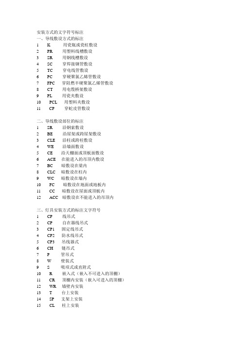
安装方式的文字符号标注一、导线敷设方式的标注1 K---------用瓷瓶或瓷柱敷设2 PR-------用塑料线槽敷设3 SR-------用钢线槽敷设4 SC-------穿焊接钢管敷设5 TC-------穿电线管敷设6 PC-------穿硬聚氯乙烯管敷设7 FPC-----穿阻燃半硬聚氯乙烯管敷设8 CT-------用电缆桥架敷设9 PL-------用瓷夹敷设10 PCL-----用塑料夹敷设11 CP-------穿蛇皮管敷设二、导线敷设部位的标注1 SR-------沿钢索敷设2 BE-------沿屋架或跨屋架敷设3 CLE-----沿柱或跨柱敷设4 WE------沿墙面敷设5 CE------沿天棚面或顶板面敷设6 ACE----在能进入的吊顶内敷设7 BC------暗敷设在梁内8 CLC----暗敷设在柱内9 WC-----暗敷设在墙内10 FC------暗敷设在地面或地板内11 CC-----暗敷设在屋面或顶板内12 ACC---暗敷设在不能进入的吊顶内三、灯具安装方式的标注文字符号1 CP-------线吊式2 CP-------自在器线吊式3 CP1-----固定线吊式4 CP2-----防水线吊式5 CP3-----吊线器式6 CH------链吊式7 P--------管吊式8 W-------壁装式9 S--------吸项式或直附式10 R-------嵌入式(嵌入不可进入的顶棚)11 CR-----顶棚内安装(嵌入可进入的顶棚)12 WR----墙壁内安装13 T-------台上安装14 SP-----支架上安装15 CL-----柱上安装16 HM-----座装本文来自:天圆地方建筑论坛,本帖原网址为/bbs/read.php?tid=54596,更多精彩,更多免费资料等着您!开关-断路器低压隔离开关:HD、HS系列隔离开关;HR系列熔断器式隔离开关;低压断路器:DW10系列框架式自动开关;DWX15、DWX15C系列万能式限流断路器;DW17(ME)系列万能式断路器;DZ10系列塑料外壳式自动开关;DZ15系列塑料外壳式断路器;DZX10系列塑料外壳式限流断路器;DZ20系列塑料外壳式断路器;DZ25系列塑料外壳式断路器;高压隔离开关:GN系列户内高压隔离开关;GW系列户外高压隔离开关;高压断路器:DW系列高压户外安装多油断路器;SW系列高压户外安装少油断路器;SN系列高压户内安装少油断路器;ZW系列高压户外安装真空断路器;ZN系列高压户内安装真空断路器;LW系列高压户外安装SF6断路器;LN系列高压户内安装SF6断路器;注:1、这里的部分型号现已停产,但还有在装的在用。
电视产品装配图中英文对照

电视产品装配图中英文对照总装配图中英文对照G29851. Firstly mount the speaker assemblies A and B (5, 6) into the front cover assemblyⅡ, then the CRTassembly (2).2. After adjustment of the two FCBs, lock them with white nitro magnetic paint Q04-3 on the shafts.3. Install the CRT rubber washer-1.5 (18) under the CRT support.4. Install the CRT with fixing torque of 3-5N.m.5. Connect wires according to the final wiring diagram and check if the wired connectors are connectedcorrectly and fixedly, and the high voltage cap and CRT RGB PCB are mounted. After inspection and ensuring O.K, reinstall the back cover6. Check and make sure that all control buttons can work flexibly and normally.34D881. Mount the rubber blocks (16) into the speaker assemblies.2. Mount the speaker assemblies A and B (5, 6) into the front cover assembly (3), then the CRTassembly (2). Fasten the degaussing coil on the claws of the CRT support as shown above. Bind bottom (on the left/right sides) of the degaussing coil and explosion-proof steel belt together with the wire clips (26) and insert the plug of the degaussing coil into the corresponding part of the inductor on the power PCB. After that, install the chassis assembly (1).3. Install the CRT notched washer (14) with notched surface upside or downside under the CRTsupport. See Fig. A-A.4. Install the CRT with fixing torque of 10.5-12.5N.m.5. Connect wires according to the final wiring diagram and check if the wired connectors are connectedcorrectly and fixedly, and the high voltage cap and CRT RGB PCB are mounted. After inspection and ensuring O.K, reinstall the back cover6. Check and make sure that all control buttons can work flexibly and normally.JUC2.025.3241. Install the CRT with fixing torque of 3.5-5N.m.2. Connect wires according to the final wiring diagram and check if the wired connectors are connectedcorrectly and fixedly, and the high voltage cap and CRT RGB PCB are mounted. After inspection and ensuring O.K, reinstall the back cover3. Check and make sure that all control buttons can work flexibly and normally.4. Warning label (5, 6, 7, 8 or 9) differs depending on CRT used and should be stuck into the backcover.JUC2.025.0521. Install the CRT with fixing torque of 4-5N.m.2. Mount the power cord (21) into the E PCB assembly (3), and then mount the assembly into the frontcover assembly (2). Insert the power wire clip into A on the front cover.3. After mounting the CRT RGB PCB into the CRT, insert the wired connector XSB08 into the wire clipon the frame heating sinking assembly and tie the wired connectors XSB08 and M06, screen wire and focus wire together with the wire clip (7).4. Connect wires according to the final wiring diagram and check if the wired connectors are connectedcorrectly and fixedly, and the high voltage cap and CRT RGB PCB are mounted. Check if the connector of the deflection yoke is inserted in the socket XSA05. After adjustment of the two FCBs, lock them with white nitro magnetic paint Q04-3 on the shafts. Reinstall the back cover after inspection and ensuring O.K.5. Check and make sure that all control buttons can work flexibly and normally.H34D801. Firstly mount the CRT assembly (2) into the front cover assembly (3), then install the supportingplate (5). Make sure that the degaussing coil is fastened among the front cover, CRT and support.Finally mount the chassis assembly (1).2. When mounting the notched washers (9), ensure each notched surface under the CRT handleupside and each over the handle downside.3. Install the CRT with fixing torque of 10.5-12.5N.m.4. Connect wires according to the final wiring diagram and check if the wired connectors are connectedcorrectly and fixedly, and the high voltage cap and CRT RGB PCB are mounted. Reinstall the back cover (4)after inspection and ensuring O.K.5. Check and make sure that all control buttons can work flexibly and normally.6. Insert the wire clip (7) onto the base plate to tie the wired connectors XPK02 and X602B together.7. Before packing, tighten and fasten the slow-acting door and front cover with the fiber-glass tape toavoid it ejected during transportation. Professional engineers decide the location depending on different situation.8. Tie wires with the wire clip (10) to prevent binding wires from coming loose and anode of FBT fromtouching CRT according to professional engineers.21C321. Install the CRT with fixing torque of 4-5N.m.2. Connect wires according to the final wiring diagram and check if the wired connectors are connectedcorrectly and fixedly, and the high voltage cap and CRT RGB PCB are mounted. Then solder the focus wire and screen wire tightly.3. Tie together the wired connectors XPY01/XS402, screen wire and focus wire of the FBT with thewire clip (18).4. Insert the wire clip into the slot on the lower left corner of the front cover.5. After adjustment, lock the two FCBs on the FBT with white nitro magnetic paint Q04-3 (17).6. After final assembly, check and make sure that no scratch and foreign objects exist on/in the set, andlabel plates are stuck fixedly. Additionally check and make sure that all control buttons can work flexibly and normally.7. Stick the fragile label (7) onto the side joint of the back cover after remounting the back cover withthe screws (14)JUC2.025.1991. Connect wires according to the final wiring diagram and check if the wired connectors are connectedcorrectly and fixedly, and the high voltage cap and CRT RGB PCB are mounted. Check if the connector of the deflection yoke is inserted in the socket T JC2-5A. After adjustment of the two FCBs, lock them with white nitro magnetic paint Q04-3 on the shafts. Reinstall the back cover (5) after inspection and ensuring O.K.2. Check and make sure that all control buttons can work flexibly and normally.3. Insert the wired connectors JUC6.604.127 and JUC6.604.128 into the wire clip XJ-20 on the mainPCB.4. Stick the sealing shock-absorption bar (18) on the middle top of the back cover sealing.JUC2.025.3281. Mount the main PCB assembly (3) into the front cover assembly (2), and then inset the wire clip onthe power cord into the front cover.2. After mounting the CRT RGB PCB into the CRT, tie the screen wire and focus wire together with thewire clip (7).3. Connect wires according to the final wiring diagram and check if the wired connectors are connectedcorrectly and fixedly. Tie the wired connectors on the left speaker, comb PCB and CRG RGB PCB (XSY01) together with the wire clip (7).4. Check and ensure correct and tight connections. Make sure that the high voltage cap and CRT RGBPCB are mounted. Check if the connector of the deflection yoke is inserted in the socket T JC2-6A.After adjustment of the two FCBs, lock them with white nitro magnetic paint Q04-3 on the shafts.Reinstall the back cover (5) after inspection and ensuring O.K. Additionally check and make sure that all control buttons can work flexibly and normally21BM15ME1. Install the CRT with fixing torque of 3-5N.m.2. Mount the main PCB assembly (3) into the front cover assembly (2), and then inse rt the connectoron the power switch assembly into the main PCB assembly (3).3. After mounting the CRT RGB PCB (4) into the CRT, tie the wired connectors XPY03 and KDY,screen wire and focus wire together with the wire clip (7).4. Connect wires according to the final wiring diagram and check if the wired connectors are connectedcorrectly and fixedly, and the high voltage cap and CRT RGB PCB are mounted. Check if the connector of the deflection yoke is inserted in the socket XSA07A. After adjustment of the two FCBs, lock them with white nitro magnetic paint Q04-3 on the shafts. Reinstall the back cover (5) after inspection and ensuring O.K.5. Check and make sure that all control buttons can work flexibly and normally.6. After installation, stick film onto the four corners according to professional engineers.21BM35ME1. Install the CRT with fixing torque of 3.5-5N.m.2. Connect wires according to the final wiring diagram and check if the wired connectors are connectedcorrectly and fixedly, and the high voltage cap and CRT RGB PCB are mounted. Check if the connector of the deflection yoke is inserted in the socket T JC2-5A. After adjustment of the two FCBs, lock them with white nitro magnetic paint Q04-3 on the shafts. Reinstall the back cover (5) after inspection and ensuring O.K.3. Tie the screen wire and focus wire together with the wire clip (20).4. Check and make sure that all control buttons can work flexibly and normally.5. Insert the wired connectors JUC6.604.127 and JUC6.604.128 into the wire clip XJ-20 on the mainPCB.6. Tie the side-set AV wired connector onto the sound heat sink with the wire clip (19).21BM69ME1. Install the CRT with fixing torque of 3.5-5N.m.2. After mounting the CRT RGB PCB (4) into the CRT, tie the wired connectors XS601, XS402, KDY,screen wire and focus wire together with the wire clip (7).3. Insert the wired connectors XS161 into the socket on the main PCB, and tie the longer wire with thewire clip XJ-20.4. Connect wires according to the final wiring diagram and check if the wired connectors are connectedcorrectly and fixedly, and the high voltage cap and CRT RGB PCB are mounted. Check if the connector of the deflection yoke is inserted in the socket XS401. After adjustment of the two FCBs, lock them with white nitro magnetic paint Q04-3 on the shafts. Reinstall the back cover (5) after inspection and ensuring O.K.5. Check and make sure that all control buttons can work flexibly and normally.5. For PF2914, the back cover (4) is screen printed with “CHANGHONG”and mounted with blankplate. For CPF2730, the back cover (4) isn’t screen printed with “CHANGHONG”and mounted with blank plate.6. Wind the wired connector XPK01 around the degaussing coil with the wire clip (9) to prevent XPK01from coming loose according to professional engineers.7. Use one of the wire clips (9) to tie the wired connector of the deflection yoke, another to tie the EHTwire, ensuring it not touching the CRT RGB PCB and VM PCB. Use the other two to tie the wired connector XPK01.8. After installation, stick film onto the four corners of the front cover according to professionalengineers.JU2.025.5071. Install the CRT with fixing torque of 3.5-5N.m.2. Connect wires according to the final wiring diagram and check if the wired connectors are connectedcorrectly and fixedly, and the high voltage cap and CRT RGB PCB are mounted. After inspection and ensuring O.K, reinstall the back cover3. Check and make sure that all control buttons can work flexibly and normally.4. Warning label (8, 9 or 10) differs depending on CRT used and should be stuck into the back cover.5. The dimension identified by “*”is only for reference.EC3413NF1. Install the CRT with fixing torque of 10-12.5N.m.2. Check and make sure that all control buttons can work flexibly and normally.3. The location where the wire clip (8) is tied and how to tie should be decided by professionalengineers and designers depending on different situation.4. Connect wires according to the final wiring diagram and check if the wired connectors are connectedcorrectly and fixedly, and the high voltage cap and CRT RGB PCB are mounted. After adjustment of the two focus VRs, lock them with white nitro magnetic paint Q04-3 on the shafts. Reinstall the back cover assembly (6) after inspection and ensuring O.K.CPF2198E1. Install the CRT with fixing torque of 3.5-5N.m.2. After mounting the CRT RGB PCB (4) into the CRT, tie the wired connector XS402, screen wire andfocus wire together with the wire clip (15).3. Connect wires according to the final wiring diagram and check if the wired connectors are connectedcorrectly and fixedly, and the high voltage cap and CRT RGB PCB are mounted. Check if the connector of the deflection yoke is inserted in the related socket. After adjustment of the two focus VRs, lock them with white nitro magnetic paint Q04-3 on the shafts. Reinstall the back cover (8) and mount the screws and nuts as per the diagram after inspection and ensuring O.K. Upon completion of final inspection, seal the set with plasticine and mark it.4. Check and make sure that all control buttons can work flexibly and normally, no scratch and foreignobjects exist on/in the set, and label plates are stuck fixedly.5. Pass the power cord through hole of the cap panel (20) on the back cover and tie it tightly to the rightwith the wire clip A (21). Then mount the cap panel and tight it with the tapping screws (12).CPF3498E1. Install the CRT with fixing torque of 8-10N.m.2. Check and make sure that all control buttons can work flexibly and normally.3. Tie the gray screen wire, red focus wire, wired connectors P701 and XPY03 with the wire clip (8)according to professional engineers and designers depending on different situation.4. Connect wires according to the final wiring diagram and check if the wired connectors are connectedcorrectly and fixedly, and the high voltage cap and CRT RGB PCB are mounted. After adjustment of the two focus VRs, lock them with white nitro magnetic paint Q04-3 on the shafts. Reinstall the back cover assembly (6) after inspection and ensuring O.K.5. After final assembly, stick the protection film onto the four corners of the front cover according toprofessional engineers.6. Stick one of the labels for serial No. bar code onto the back cover and the other onto the cartonaccording to professional engineers.C3418E1. Install the CRT with fixing torque of 8-10N.m.2. Tie the gray screen wire, red focus wire, wired connectors P701 and XPY03 with the wire clip (8) toprevent the wired connectors from contacting with high-temperature components according to professional engineers and designers depending on different situation.3. Tie wire of the degaussing coil with the binding wire XJ-100 (18) to prevent the degaussing coil fromcontacting with high-temperature components according to professional engineers and designers depending on different situation.4. Connect wires according to the final wiring diagram and check if the wired connector s are connectedcorrectly and fixedly, and the high voltage cap and CRT RGB PCB are mounted. After adjustment of the two focus VRs, lock them with white nitro magnetic paint Q04-3 on the shafts. Reinstall the back cover (7) after inspection and ensuring O.K.5. Check and make sure that all control buttons can work flexibly and normally.6. After final assembly, stick the protection film (22) onto the four corners of the front cover according toprofessional engineers.显像管组件中英文对照1. Fasten the degaussing coil on the CRT tightly, and then bind the coil onto the hole of the CRT steelbelt tightly.2. Types of the degaussing coil and CRT are subject to the circuit parts list.面框组件中英文对照21BM15ME1. Paint outer surface of the front cover, MAIN POWER SWITCH button, six-button with plastic paintP-32 in accordance with QB/JU106-89.2. Mount the lens (13) and six-button (11), then the front AV PCB assembly (6), KZ PCB assembly intothe front cover.3. Tie the power switch assembly and make sure that all control buttons can work flexibly and normally.4. Refer to the parts list about specifications of the speakers.5. Hot-driven rivet tightly at ①-⑥point and ensure the front panel fits the front cover tightly and no gapexists on top of the front cover, not affecting adversely mounting of the CRT.21BM35ME1. Characters must be clearly screen-printed without bur in ink YM-9.2. Mount the MAIN POWER SWITCH button (7), reset spring (9) and lens (10, hot-drivenriveted at 4 points) into the front cover (6).3. Fix the side-set AV board assembly (4) onto the front cover (6) with the tapping screws(16), and then stick a side-set AV plate (11).4. Refer to the parts list about specifications of the speakers.5. Paint outer surface of the shaded front cover A with plastic paint P-36, all outer surfaceother than the shaded front cover A, out surface of left/right decoration plates and surface of MAIN POWER SWITCH button and six-button with plastic paint P-32.21BM69ME1. Paint outer surface of the front cover A with plastic paint P-11 and other outer surface plasticpaint P-9.2. Paint out surface of the MAIN POWER SWITCH button (3) and six-button (4) with plasticpaint P-9.3. Characters must be clearly screen-printed without bur in ink YM-9.4. Mount the MAIN POWER SWITCH button (3), reset spring (5) and lens (6, hot-drivenriveted at 4 points) into the front cover (2).1. Mounts all parts and jumpers in accordance with the related parts list.2. Print production date on blank of the label with red ink according to the profession al engineersbefore crestal welding.3. Solder tightly pins of all the radiator (heat sink) assemblies and FBT.4. The PCB code is subject to the related parts list.5. The professional engineers decide the location where the label for chassis No. and date (19) isstuck..1. Mounts all parts and jumpers in accordance with the related parts list.2. Print production date on blank of the label with red ink according to the professional engineersbefore crestal welding.3. The PCB code is subject to the related parts list.4. Tie the wired connectors XSB06, XSB08 on the CRT RGB PCB with the wire clip (3).JUC5.861.2911. Check and make sure no scratch and defect on the surface and no deformation affecting mounting.JUC5.861.2921. Check and make sure no scratch and defect on the surface and no deformation affecting mounting.2. IC options: MC7812C or L7812CV or N7812JUC5.861.1651. The IC specifications are subject to the related circuit parts list.JU5.861.1691. Mount the foot B fixedly. Each foot can bear tensile strength (F) of over 50N.2. Check and make sure no scratch and defect on the surface and no deformation affecting mounting.2. Print production date on blank of the label with red ink according to the professional engineers.6. Paint outer surface of the front cover with plastic paint in accordance with QB/JU106-89.7. Refer to the above table about color order of each component during final assembly.9. The power cord should be inserted into the slot of the back cover before installment.机芯组件中英文对照1. Fasten the assemblies (2, 3, 4 and) onto the chassis frame with screws (14) accordingto the diagram.2. Mount the AV PCB assembly (5) onto the main PCB assembly according to the diagram.Then secure the rear terminal board (7) onto the chassis frame with screws (15) and stick the AV plate (11). Finally fasten the AV PCB assembly onto the rear terminal board.3. Insert the wired connectors into the corresponding socket as per the diagram andensure them connected fixedly and properly.4. Tie the wired connectors XS803 and XS804 with wire clips (9).DVD接线图中英文对照1. 解码板组件上的带线插头均焊于印制板上。
电气设计图名称中英文对照

14
项目名称 PROJECT NAME 装置/工区名称 UNIT NAME 工作号 JOB NO./WBS NO. 阶段 PHASE 页码 SHEET 版次 REV.
全厂电气图纸目录 ELECTRICAL DOCUMENT INDEX FOR GENERAL PLANT
单元名称 SECTION NAME 项目号 PROJECT NO. 文件号 DOC. NO.
图纸/文件号 NUMBER OF DRAWING/DOCUMENT
版次 尺寸 REV SIZE
数量 Q'TY
备注 Remarks
16
17
18
19
20
21 22 23
24
项目名称 PROJECT NAME 装置/工区名称 UNIT NAME 工作号 JOB NO./WBS NO. 阶段 PHASE 页码 SHEET 版次 REV.
全厂电气图纸目录 ELECTRICAL DOCUMENT INDEX FOR GENERAL PLANT
单元名称 SECTION NAME 项目号 PROJECT NO. 文件号 DOC. NO.
2/2
序号 NO. 15
图纸/文件名称 TITLE OF DRAWING/DOCUMENT 爆炸危险区域划分图(立面E-E) Hazardous Area Classification(Section E-E) 爆炸危险区域划分图(立面L-L) Hazardous Area Classification(Section L-L) 全厂危险区域划分图 Overall Hazardous Area Classification 动力平面图图例及说明 Power Layout Legend And Notes 电缆桥架说明及图例 Cable tray General Notes And Symbol & Legend 电伴热电缆管线表 Electrical Cable List For EHT 照明和插座说明及图例 Lighting & Socket General Notes And Legend 道路照明平面图 Road Ligthing Layout 防雷接地说明及图例 Lightning And Earhting General Notes And Legend 全厂接地平面图 Overall Plant Gounding Layout Diagram
中英文安装说明书

Enclosure Climate Control Unit工业控制柜制冷机Assembly Instructions安装说明书(ECC 系列)内容1.应用场合2.技术参数3.安装方式4.安全与注意5.电气连接6.常规操作7.工作原理8.维护保养9.质量保证10.电气原理图11.安装尺寸图1.应用场合工业控制柜制冷机通过把控制柜的空气冷却同时把柜内热量驱散出柜外,从而保护控制柜内的电气元件在可控的范围内运行。
制冷机同时具有除湿功能,保证控制柜内有理想的温度和湿度。
2.技术参数壁装系列型号 ECC225ECC320 ECC680 ECC825设计电压VAC/ Hz230/50可用制冷功率W(L35 L30)225 320 680 825外形尺寸(H×W×D)mm445×286×181 630×350×190 制冷剂 R134a环境温度/可调节范围(℃) 20~55 / 20~38重量(Kg) 15 16 26 28型号 ECC1100ECC1500设计电压VAC/ Hz230/50可用制冷功率W(L35 L30)1100 1500外形尺寸(H×W×D)mm400×1000×240制冷剂 R134a环境温度/可调节范围(℃) 20~55 / 20~38重量(Kg) 38 41顶装系列型号 ECC680T ECC1100T ECC1500T设计电压VAC /Hz230/50可用制冷功率W680 1100 1500外形尺寸(H×W×D)mm350×527×335 410×608×427制冷剂 R134a R22环境温度/可调节范围(℃) 20~55 / 20~38重量(Kg) 26 36 403.安装方式根据产品的型号,制冷机可以有壁装,顶装,两种安装方式,开孔图详见下面的安装尺寸图3.1外挂式按照开孔图开孔,把相应型号的制冷机用随附的螺钉先安装到控制柜上,使用制冷机后面的内六角螺钉与控制柜锁紧。
ISO电气安装设计流程图英文版

No Validation of design checked by
qualified person
Client confirms acceptance of design
JHE produces consultation drawings, if required
Confirmation: E-mail Signed approval Fax Scan
Audit Findings
Enquiries & Tenders
Arrange & meet with client
Client produces functional design specification
Does specification require JHE assistance?
Yes JHE assists in completion of comprehensive specification
Control of Drawings
Client checks drawings
JHE select materials
Approved Suppliers/ Subcontractos
Distribution Equipment Luminaires Containment Cable sizes Accessories
No
Yes
Complete final inspection sheet
May 2015
Issue No: 1
ISO 9001 : 2008 Reference : 5.2 Customer Focus; 7.3 Design & Development 7.5.1 Control of Service Provision; 7.5.3 Identification and Traceability
电气施工图设计说明(中英文互译)

电气施工图设计说明一.建筑概况本建筑为框架结构,功能分为:生产区、管理区和仓库区,生产区为二层,管理区为三层,仓库区为一层。
仓库区内的装卸区为三层。
层高:生产区:一层:5.5M;二层:6.25M;管理区:4.0M ,4.25M(有吊顶及架空地板);仓库区:11.75M;总建筑面积:9129M2。
Design Specifications for Electric Constructional DrawingsI Building profileThis building is of frame structure, the functions of which can be divided into producing area, managerial area, and warehouse area. The producing area is two- story, three stories for the managerial area, and one story for the warehouse area. There is a three- story loading and unloading area inside the warehouse area. Story height: producing area: one story: 5.5 meters; second story: 6.25 meters; managerial area: 4.0 meters and 4.25 meters (with suspended ceiling and aerial floor board); warehouse: 11.75 meters; total constructional area: 9129 square meters.二.设计依据:《供配电系统设计规范》(GB50052-95)《工业与民用电力装置的接地设计规范》(GBJ65-83)《建筑设计防火规范》(GBJ16-87 2001)《低压配电设计规范》(GB50054-95)《建筑物防雷设计规范》(GB50057-94)II Basis for Design“Design Specifications for Power Supply and Distribution System” (GB50052-95) “Design Specifications for Earthing for Industrial and Civil Power Installations” (GBJ65-83) “Specifications for Fire Control in Architectural Design” (GBJ16-87 2001)“Design Specifications for Low Voltage Distribution” (GB50054-95)“Lightning Protection Design Specifications for Buildings” (GB50057-94)三.设计范围:本工程设计范围包括:厂区总图界区内建筑物的低压供配电、照明、防雷及接地设计。
电气产品安装指南说明书

ELECTRICAL SAFETY INSTRUCTIONS All connections must be installed by a licensedelectrician, in accordance with current building codes. Consult a qualified electrician.IMPORTANTAlways switch off the electrical supply at the main during installation and maintenance. It isrecommended that the circuit breaker is switched off for the necessary circuit before installation commences.Fitting in Bathrooms is subject to the appropriate building code Regulations. This product is NOT suitable for outside zones. It is also Not suitable for installation in saunas, steam rooms or showercubicles. This product is only suitable for permanent installation. DO NOT connect to a trailing plug and socket outlet. This product is only suitable for indoor use. Do not attach the product to surfaces that are damp or otherwise electrically conductive.INSTALLATION CARE & SAFETYWear suitable eye protection when drilling. Take care when using power tools. Beware of hidden cables or pipes. Take care if drilling on tiled surfaces in case the drill slips. A piece of masking tape applied to the wall before marking out the fixing holes will stop the drill from wandering.CLEANINGIt is recommended that the unit is cleaned with a soft, dry, non abrasive cloth when turned off. Never use cleaning agents or abrasive materials on any type of surface finish. Do not allow moisture to come into contact with the electrical components.125 Rt. 61 Schuylkill Haven, PA 179721-800-360-1585 • fax 570-385-5475 • info@ltlhomep r www .ltlhomep r IMPORTANTDO NOT strike glass components with hard or pointed items. DO NOT place very hot or very cold items against or in close proximity to glass surfaces unless an adequately thick insulation materal is used to prevent such items coming in contact with the glass. The nominal thickness of the mirror glass used in this product is 1/4” and is flm backed for safety. If the glass becomes chipped or broken replace immediately.Installation Instructions2. Using a level, mark off a horizon tal line, and ensure that the ends of the brackets are spaced to the width between the inner edges of the vertical aluminiumextrusions (see illustration 1). Mark off the holes using a pencil.3. Note: Screws supplied are only suitable for stud walls. For drywall walls use special wall fasteners,available from DIY or hardware stores. Seek advice froma specialist about the suitability of screws to be used. Drill the required holes and insert wall screws.4. Screw the bracket tothe wall using the screws provided. Please ensure the screws are fully tight but take care not to overtighten.5. Before making any electrical con-ply. This unit is provided with a supply cable already fit-ted. This cable should be fitted to the household lighting circuit or to a fused 3 AMP supply. Connections should be made in accordance with the latest regulations. This cabinet is manufactured to CLASS 1 and requires an earth connection.Illustration 1NewportLED ILLUMINATED MIRRORr OPERATING INSTRUCTIONS• To turn ON or OFF the LEDs, wave the hand across the IR sensorCHANGE LIGHT INTENSITY• Hold the hand in f r ont of the IR senso r, while the mi rr or lights a re ON, until desi r ed brightness is achi eved.• Restart by waving the hand across the sensor at preselectedintensity settings.Portrait or Landscape1. Remove the packaging careully,do not lose the screwsThe next step is to make the electrical connection from the mirror to themains supply. Use the connection wire found at the rear of the mirror to make the necessary connections. A second person will need to hold the mirror in place whilst made.THIS PRODUCT IS MANUFACTURED TO CLASS ICATEGORY AND MUST HAVE AN EARTH CONNECTION.! IF IN DOUBT CONSUL T YOUR ELECTRICIAN !electrical connections are 125 Rt. 61 Schuylkill Haven, PA 179721-800-360-1585 • fax 570-385-5475 • info@ltlhomep r www .ltlhomep r 。
电器图中各术语英文解释
电器(di^nqi)图中各术语英文解释电器(dianqi)图中各术语英文解释电器图中各术语(sh^yfl)英文解释第一(d1yi)部分GCK、GCS、MNS是低压(diyd)抽出式开关柜;GGD、GDH、PGL是低压(diyd)固定式开关柜;XZW综合(zOnghO)配电箱;ZBW箱式变电站;XL、GXL低压配电柜、建筑工地箱;JXF电器控制箱;PZ20、PZ30系列终端照明配电箱;PZ40、XDD(R)电表计量箱PXT(R)K-□/□-□/□-□/□-D/IP□系列规格型号解释:(1)PXT明装配电箱,暗装加(R)(2)K有如表1的系列配线方式(3)□/□额定电流/额定短时耐受电流能力:用数字表示,250/10表示:额定电流250A/额定短时耐受电流能力10kA,根据顾客要求可以降低。
(4)□/□进线型式:□/1单相输入;口/3三相输入;1/3表示混合输入(5)□X^出线回路:单相回路X三相回路,6X3单相6回路,三相3回路(6)□/□主开关型式/防护等级;1/IP30单相(danxiang)主开关/IP30;3/IP30三相主开关/IP30表1:序号汉语拼音字头中文解释(jiQshi)装配图号电气原理图号1几计量(jilidng)箱PXT01PXT01dq系列2CZ插座(chazud)箱PXT02PXT02dq系列3ZM照明(zhdoming)箱PXT03PXT03dq系列4DL动力箱PXT04PXT04dq系列5JC计量插座箱PXT05PXT05dq系列6JZ计量照明箱PXT06PXT06dq系列7JD计量动力箱PXT07PXT07dq系列8ZC照明插座箱PXT08PXT08dq系列9DC动力插座箱PXT09PXT09dq系列10DZ动力照明箱PXT10PXT10dq系列11HH混合功能箱PXT11PXT11dq系列12ZN智能箱PXT12PXT12dq系列表二:电气箱柜名称编号规格型号高压开关柜AH高压计量柜AM高压配电柜AA高压电容柜AJ低压电力(didnli)配电箱柜AP低压(diyd)照明配电箱柜AL应急电力配电(pdidian)箱柜APE应急照明配电(p^idian)箱柜ALE低压负荷开关(kaiguan)箱柜AF低压电容补偿柜ACC或ACP直流配电箱柜AD 操作信号箱柜AS控制屏台箱柜AC继电保护箱柜AR计量箱柜AW 励磁箱柜AE低压漏电断路器箱柜ARC双电源自动切换箱柜AT多种电源配电箱柜AM刀开关箱柜AK电源插座箱AX建筑自动化控制器箱ABC火灾报警控制器箱AFC设备监控器箱ABC住户配线箱ADD信号放大器箱ATF分配器箱AVP接线jidxidn)端子箱AXT举例说明吧例一:GCK第一个G代表(ddibido)配电柜第二个C代表(ddibido)抽屉式第三个K代表(ddibido)控制例二:GGD第一个G代表(ddibido)配电柜第二个G代表固定式第三个D代表动力第二部分配电箱1LA1a1AL1bAT-DT是什么意思还有1AP22AP13APc7AP1KX 之类的。
- 1、下载文档前请自行甄别文档内容的完整性,平台不提供额外的编辑、内容补充、找答案等附加服务。
- 2、"仅部分预览"的文档,不可在线预览部分如存在完整性等问题,可反馈申请退款(可完整预览的文档不适用该条件!)。
- 3、如文档侵犯您的权益,请联系客服反馈,我们会尽快为您处理(人工客服工作时间:9:00-18:30)。
中英文电气安装说明和图例LUMINAIRE 灯具1x28W T5 Batten Surface/Wall Mount fluorescent fitting1x28W T5 条形表面安装/壁装荧光灯2x28W T5 Batten Surface/Wall Mount fluorescent fitting2x28W T5 条形表面安装/壁装荧光灯1x28W T5(IP65) fluorescent fitting1x28W T5 (IP65) 荧光灯2x28W T5(IP65) fluorescent fitting2x28W T5 (IP65) 荧光灯1x14W Batten Surface/wall mount fluorescent fitting1x14W 条形表面安装/壁装荧光灯2x28W recessed/suspended mount luminaire fitting2x28W 嵌入式/悬挂式灯具1x240W metal halide fitting1x240W 金属卤化灯具1x18W (IP65) surface mounted luminaire1x18W(IP65) 表面安装的照明灯具1x26W Rectangular wall recessed luminaire1x26W 方形墙面嵌入式照明灯具2x28W Fluorescent fitting C/W prismatic diffuser2x28W 荧光灯,包括棱镜式散光罩1x26W PLC recessed down-light1x26W PLC 嵌入式筒灯2x26W PLC recessed down-light2x26W PLC 嵌入式筒灯2x18W PLC recessed down-light2x18WPLC 嵌入式筒灯11W recessed/suspended mount down-light11W 嵌入式/悬挂式筒灯1x150W high bay light1x150W 高顶灯2x55W weatherproof (IP54) aircraft obstruction light2x55W 防雨(IP54)航空障碍灯A-denotes fitting connected to battery pack (type as above)A指示灯,同电池组相连接(类型同上)Single sided exit light (Type E1)单侧出口灯(类型E1)Similar to Type E1 but with an additional arrow pointing to the right (Type E2)同类型E1相似,但是多一个向右的指示箭头(类型E2)Similar to Type E1 but with an additional arrow pointing to the left (Type E3)同类型E1相似,但是多一个向左的指示箭头(类型E3)Double faced exit light with an additional arrow on each face pointing to the left/right as appropriate (Type E4)双面出口灯,每面多一个指示箭头,指示左或者右(视情况而定)(类型E4)Similar to Type E1 but with an additional arrow pointing to the opposite directions (Type E5) 同类型E1相似,但是多一个指示箭头,指示相反的方向(类型E5)Switches开关LTG SW., 1 Gang One-way(Lighting)照明开关,1组单向LTG SW., One-way (2S denotes 2 Gang)照明开关,单向(2S表示2组)LTG SW., Two-way照明开关,双向LTG SW., Two-way (2S denotes 2 Gang)照明开关,双向(2S表示2组)Intermediate LTG SW., 1Gang中间照明开关,1组Intermediate LTG SW (2S denotes 2 Gang)中间照明开关(2S表示2组)Weatherproof LTG SW防雨照明开关Flameproof LTG SW防火照明开关DP LTG SW., 1Gang One-way双杆照明开关(Double Pole),1组单向Intermediate LTG SW (2S denotes 2Gang)中间照明开关(2S表示2组)Weatherproof LTG SW防雨照明开关Splash-proof LTG SW防溅式照明开关DP LTG SW., 1 Gang One-way双杆照明开关,1组单向Lighting switch panel照明开关柜Denotes switches of metal-clad type金属壳开关(铠装)Dimmer C/W switch调光器,包括开关Dimmer rack调光柜Dimmer switch panel (Digital type)调光器开关柜(数字型)20A DP switch C/W neon indication lamp and marked “water heater”20安培双杆开关,包括氖管指示灯,并标示“热水器”20A DP switch C/W neon indication lamp and marked “washing machine”20安培双杆开关,包括氖管指示灯,并标示“洗衣机”Bell push switch marked with Bell symbol铃按钮开关,并标记有“铃”符号Door chime point门铃Buzzer point蜂铃ElectricalAir/oil/vacuum circuit breaker (Rating and No. of poles as shown)空气、油压、真空断路器Moulded case/miniature circuit breaker (Rating and No. of poles as shown)断路器模块、小型断路器(跳菲)Residual current circuit breaker (RCCB) Rating and No. of poles as shown漏电断路器、漏电保护器DB/MB/MP/SSB/ESSB/LSB/LDB配电盘、量表板、计量盘、分配电板、电梯配电盘MSB/EMSB/GCP/PCP主配电柜、发电机控制箱、泵控制箱Subsidiary control panel辅助控制柜Tenant’s metering panel C/W MCBs subsidiary control panel and isolating SW. to powergrid’s approval租户计量盘,包括微型断路器二级控制箱和隔离开关(获得电网批准)Over-ground distribution box地上配电箱Isolation SW (Rating as shown)隔离开关Fuse switch (Rating as shown)熔丝开关、保险丝开关Switch-fuse (Rating as shown)开关熔断器、开关保险丝Fireman’s switch消防开关Junction box接线箱Cable end C/W termination kit电缆端头,包括端子箱Ammeter安培表V oltmeter电压表Power factor meter功率因数表Frequency meter频率计Kilowatt meter电力计、千瓦计Kilowatt-hour meter电表Maximum demand meter with alarm最大需量计,带警报Hour run meter运行小时计Energy monitoring device comprising current transformers, transducers, etc. For remote reading/logging of kilowatt-hour consumption能量监测装置,包括电流变压器、变送器等,用于远程读取、记录电能损耗Overcurrent/earth fault protection relay with instantaneous high set element (IDMTL characteristic unless otherwise indicated)过电流、接地故障保护继电器。
Overcurrent protection relay with instantaneous high set element (IDMTL characteristic unless otherwise indicated)过电流保护继电器Earth fault relay (IDMTL characteristic)接地故障继电器Earth fault delay with definite time lag接地故障继电器(时滞、时迟)Earth leakage relay接地漏电继电器Restricted earth fault relay受限接地故障继电器Solid-state zone selective earth fault relay固态区域选择性接地故障继电器Pilot wire protection relay控制线路保护继电器HRC fuse (Rating as shown)高断开容量保险丝Pilot indicating light航向指示灯Selector SW选择器开关Time SW C/W by-pass SW定时开关,包括旁路开关Remote trip push button远程跳闸按钮开关Change-over contactor (Rating & No. of pole as shown)切换触头(接触器)Automatic transfer SW (Rating as shown)自动换向开关Manual transfer SW (Rating as shown)手动换向开关Current transformer电流变压器V oltage transformer电压变压器HRC fused tap-off unit (Rating as shown)高断开容量熔接分线设备(见额定值)MCCB Tap-off Unit (Rating as shown)模块断路器分线设备(见额定值)Busbar termination box母排端接箱End feed unit端部馈电装置Center feed unit中心馈电装置Standby generator set备用发电机组Power transformer电源变压器FanCeiling fan吊风扇Wall mounted fan壁挂风扇Ceiling oscillating fan吊式摇头风扇Fan regulator C/W SW风扇调节器,包括开关Power: SSO—开关插座13A SSO, 1 Gang (Switched Socket-outlet)13A 开关插座,1组13A SSO, 2 Gang13A开关插座,2组13A Weatherproof SSO13A 防雨开关插座13A SSO mounted at high level13A 开关插座,安装于高处13A Splash-proof SSO (For washing machine)13A 防溅开关插座(用于洗衣机)15A splash-proof SSO (For washing machine)15A 防溅开关插座(用于洗衣机)13A metalclad SSO mounted within false ceiling space13A 金属壳开关插座(假吊顶内)15A metalclad SSO mounted within false ceiling space15A 金属壳开关插座(假吊顶内)13A SSO mounted within false ceiling space (For air conditioner)假吊顶内安装的13A 开关插座(用于空调)13A SSO mounted within false ceiling space (For hand dryer/hair dryer)假吊顶内安装的13A开关插座(用于烘手机、吹风机)13A SSO mounted within false ceiling space (For flush valve)安装于假吊顶内的13A开关插座(用于冲洗阀)Denotes SSOs of metalclad type表示金属壳式开关插座13A fused connection unit13A熔接装置20A fused connection unit20A熔接装置13A connection unit连接装置20A connection unit 连接装置C-denotes mounted within false ceiling spaceC表示安装于假吊顶内HL-Denotes mounted at high levelHL表示安装于高处Cooker control unit炊具控制装置Sound SystemSurface mounted (wall/ceiling) loudspeaker安装于表面(墙面、天花顶)的扬声器Loudspeaker (recessed in false ceiling)嵌入假吊顶内的扬声器Column loudspeaker音柱Ceiling loudspeaker (For emergency announcement only)吸顶式扬声器(ceiling mounted loudspeaker),仅用于紧急通知Horn loudspeaker喇叭形扬声器Amplifier (Rating as shown)扩音器Microphone input麦克风(传声器)输入口Speaker volume control扬声器音量调节器PA interface for local reinforcement sound system用于局部增强音响系统的公共广播接口Override control for the local sound system用于局部音响系统的过调节控制Telephone Installation电话安装Telephone outlet电话出线口Telephone outlet (Floor mounted type)电话出线口(地面安装式)Telephone outlet (Mounted on floor pedestal)电话出线口(安装于地面柱墩上)Telephone outlet (Mounted flush with floor finishes)电话出线口(安装高度同完成地面齐平)Distribution panel配电箱Telephone termination box (Terminal Box)电话端接箱(端子箱)Intermediate distribution frame中间配线架Private automatic branch exchange专用自动交换分机Computer Installation计算机安装Knock-out box C/W blank plate mounted flushed with FLR finishes (For computer) 分离箱,包括盲板,同完成地面齐平Computer outlet计算机电源插座Security System安保系统Videophone 可视电话Visitor call panel访问者呼叫面板Door alarm contact门报警触头Magnetic shutter door contact磁性百叶门触点Window alarm contact窗户报警触头Card access reader门禁读卡器Movement detector 移动探测器Infra-Red Detector红外线探测器Vibration detector震动检测器Master unit for fireman intercom system消防员内部通信系统主部件Fireman intercom outlet消防员内部通信插座Building intercom outlet建筑内部通信插座Master building intercom主建筑内部通信Panic button应急开关、紧急按钮Panic bolt lock应急螺栓锁Watchman/guard tour station看护、门卫值班站Local alarm bell局部报警铃Local alarm panel 局部警报控制盘Electric lock interface point (Electric lock by others)电动锁接口(其他方安装电动锁)Fixed type CCTV Camera (Wall mounted/suspended)固定式CCTV摄像头(安装于墙面或者悬挂式)Fixed type CCTV camera (Housed in a weather-proof housing)固定式CCTV摄像头,带防雨外罩Camera with pan/tilt/auto iris and pre-positioning facilities自动光圈式摄像头和预定位设施Camera with pan/tilt/zoom/auto iris and pre-positioning facilities可变焦距摄像头/自动光圈式摄像头和预定位设施CCTV camera with standard lens concealed in wall or ceilingCCTV 摄像头,镜片隐藏在墙内或者天花板内CCTV camera with pin hole lens concealed in wall or ceilingCCTV 摄像头,针孔镜头隐藏在墙内或者天花板内MATV Installation主天线电视安装TV/FM Co-Axial outletTV/FM同轴插座2-way splitter 2向分流器4-way splitter 4向分流器1-port tap-off unit单孔分线设备2-port tap-off unit双孔分线设备4-port tap-off unit 四孔分线设备Multi-tap unit (n denotes NOs of ways)转接插座装置1-port terminal unit (end unit)单孔终端设备2-port terminal unit (end unit) 双孔终端设备4-port terminal unit (end unit) 四孔终端设备Distribution amplifier 配电放大器75 OHM resistor 75欧姆电阻器Cable tray/ladderCable tray for Tel. cable 电话电缆桥架Cable tray for Elect.Cable 电气电缆桥架Cable tray for Computer cable 计算机电缆桥架Cable ladder for Tel. cable 电话电缆梯架Cable ladder for Elect.Cable 电气电缆梯架Earthing SystemEarthing point (For Elect.Installation)电气安装接地点Earthing point (For lightning protection system)防雷系统接地点Earthing point (For generator installation)发电机安装接地点Earthing point (For computer installation)计算机安装接地点Earthing point (For telephone installation)电话安装接地点Earthing point (For underground fuel storage tank)地下燃料储存箱接地点Lightning Protection SystemAir terminal 避雷针Lightning stubTape joint 带条粘接缝Down conductor引下线25mm x 3mm tape (Copper unless otherwise indicated) 25mm x 3mm 铜带25mm x 3mm aluminum tape 25mm x 3mm 铝带GeneralAll SSOs,isolating switches, etc. marked“WP” shall be of the weather-proof type 标示为WP的全部转化电器插座、隔离开关,应该是防雨型的。