IBM小型机硬件架构
IBM-POWER6-570小型机硬件管理与维护
lsdev -C | grep mem #查看物理内存状态
lsattr -El mem0
#查看物理内存属性
lsdev -C | grep proc #查看物理CPU状态
lsattr -El procX
#查看物理CPU属性
pmcycles –m
#查看逻辑CPU属性
第14页,共24页。
PCI adapters
用,逻辑设备名允许访问。
lsdev -C
第20页,共24页。
热拔插设备更换
#lsdev -C | grep cd0
#rmdev -l cd0
#lsdev -C | grep cd0
#mkdev -l cd0 #lsdev -C | grep cd0
#rmdev -dl cd0
#diag #lsdev -C | grep cd0 #cfgmgr #lsdev -C | grep cd0
#查看设备状态
#将设备从available转为defined
#将设备从defined转为available
#彻底删除
第21页,共24页。
磁盘
FC 5756 IDE Slimline DVD-ROM Drive
FC 5757 IBM 4.7 GB IDE Slimline DVD-RAM Drive
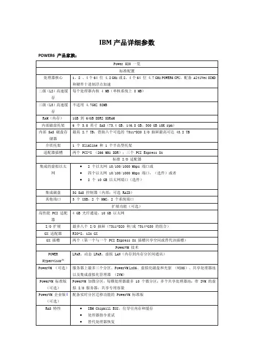
IBM小机产品详细参数
IBM PowerHA™系列
电源要求
200v到240v AC
系统规格
560构建模块:6.85英寸(高)(1U)x 19.0英寸(宽)x 32.4英寸(深)(174毫米x 483毫米x 824毫米);重量:140.0磅(63.6千克)4
有限保修
三年7X24小时售后服务,不另行收费;选定组件现场维修;所有其他元件按CRU(客户可更换元件)执行(因国家/地区而异)。提供保修服务升级和维护。
每两颗内核共享32 MB三级缓存
每个系统64 MB二级缓存
每个系统256 MB三级缓存
RAM(内存)
2 GB到48 GB的667 MHz DDR2内存;或
16 GB到96 GB的533 MHz DDR2内存;或
32 GB到192 GB的400 MHz DDR2内存
192 GB的667 MHz DDR2或
GX适配器
RIO-2,12x GX
GX插槽
2个(每个与一个PCI 8x插槽共享空间并将其替换)
PowerVM技术
POWER Hypervisor™
LPAR、动态LPAR、虚拟LAN(内存到内存分区间通讯)
PowerVM(可选)
服务器上最多三个分区、PowerVM Lx86、虚拟化磁盘和光驱(VIOS)、共享处理器池以及集成虚拟化管理器(IVM)
IBM i 5.4或更高版本
SUSE Linux Enterprise Server 10 for POWER(SLES10 SP1)或更高版本;Red Hat Enterprise Linux for POWER 4.5版(RHEL4.5)或更高版本;RHEL5.1或更高版本
高可用性
IBM PowerHA系列
IBM Power6系列570小型机产品介绍
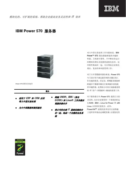
模块化的、可扩展的系统,帮助企业提高业务灵活性和 IT 效率IBM Power 570 服务器对大中型交易处理工作负载来说,IBM Power™ 570 服务器能够提供卓越的性能、主机级可靠性、不中断业务运行的模块化增长及创新的虚拟化技术。
这些特性集成在一起,可以帮助企业简化增长、复杂性和风险管理工作。
对于大中型数据库服务来说,Power 570专门设计用于满足最苛刻的关键后端工作负载的要求。
经证实,570服务器能够跨越多个数据库解决方案和操作系统提供卓越性能,是帮助公司真正迎接最重要的 IT 资产(即数据库)挑战的重要工具。
对于服务器合并,Power 570 提供巨大的灵活性,允许企业使用同一个系统同时运行AIX®、IBM i 、Linux for Power 和 x86 Linux 应用的任意组合。
此外,PowerVM ™ 虚拟化技术允许企业跨越上述所有环境动态调配资源,以便优化性能和效率,同时最大限度地减少能源使用量。
通过 Power 570,您可以轻松控制整个业务环境。
在满足整个业务系统的需求方面,Power 570通过独特的方式将多个工作负载的性能和可用性特性结合在一起,以便保持您的业务正常运行。
此外,PowerVM 虚拟化技术能够帮助您最大限度地提高运行效率,不中断业务运行的增长选项设计用于帮助您控制业务成本。
570服务器在一个集成的节能产品中提供上述全部特性,无疑是一个极佳的业务解决方案。
570服务器在最受欢迎的最新版本中最多可支持 32 个POWER6™ 处理器内核,每个构建块支持的处理器内核数量是上一个版本的两部,但仍然沿用了模块化设计,从而提高了每个系统的性能和空间利用率,最重要的是提提高了每瓦性能比。
这个版本是 570 产品家族中能效最高的的产品,适用于高度重视总体系统吞吐量的多个应用环境。
IBM Power 570 是总共包括四个组件的模块化服务器,采用可安装在机柜中的配置。
IBMPower755小型机产品介绍.
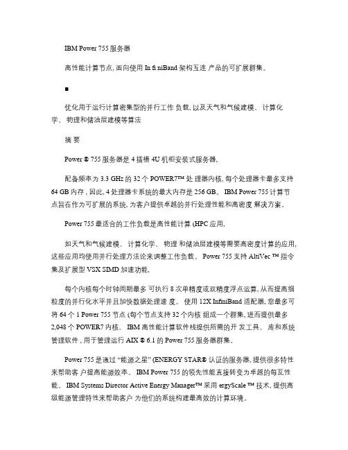
IBM Power 755服务器高性能计算节点, 面向使用In fi niBand 架构互连产品的可扩展群集。
■优化用于运行计算密集型的并行工作负载, 以及天气和气候建模、计算化学、物理和储油层建模等算法摘要Power ® 755服务器是 4插槽 4U 机柜安装式服务器,配备频率为 3.3 GHz的 32个POWER7™ 处理器内核, 每个处理器卡最多支持64 GB内存 , 因此, 4处理器卡系统的最大内存是 256 GB。
IBM Power 755计算节点旨在作为可扩展的系统, 为客户提供卓越的并行处理性能和高密度解决方案。
Power 755最适合的工作负载是高性能计算 (HPC应用,如天气和气候建模、计算化学、物理和储油层建模等需要高密度计算的应用, 这些应用均使用并行处理方法论来调整工作负载。
Power 755支持AltiVec ™ 指令集及扩展型 VSX SIMD加速功能,每个内核每个时钟周期最多可执行 8次单精度或双精度浮点运算, 从而提高细粒度的并行化水平并且加快数据处理速度。
使用12X InfiniBand 适配器, 您最多可将 64个 1 Power 755节点 (每个节点支持 32个内核组成一个群集, 进而提供最多2,048个 POWER7内核。
IBM 高性能计算软件栈提供所需的开发工具、库和系统管理软件 , 用于管理运行 AIX ® 6.1的 Power 755服务器群集。
Power 755是通过“能源之星” (ENERGY STAR® 认证的服务器, 提供很多特性来帮助客户提高能源效率。
IBM Power 755的领先性能直接转变为卓越的每瓦性能。
IBM Systems Director Active Energy Manager™ 采用ergyScale ™ 技术, 提供高级能源管理特性来帮助客户为他们的系统构建最高效的计算环境。
领先的 POWER7性能POWER7处理器的领先性能允许您加速应用运行并且减少所需的服务器节点数量, 从而降低基础架构成本。
IBM小型机Power595结构
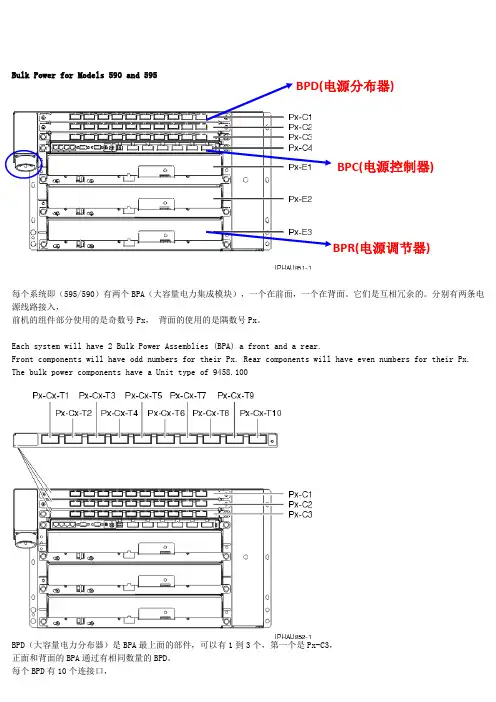
Bulk Power for Models 590 and 595BPD(电源分布器)BPC(电源控制器)BPR(电源调节器)每个系统即(595/590)有两个BPA(大容量电力集成模块),一个在前面,一个在背面。
它们是互相冗余的。
分别有两条电源线路接入,前机的组件部分使用的是奇数号Px,背面的使用的是隅数号Px。
Each system will have 2 Bulk Power Assemblies (BPA) a front and a rear.Front components will have odd numbers for their Px. Rear components will have even numbers for their Px. The bulk power components have a Unit type of 9458.100BPD(大容量电力分布器)是BPA最上面的部件,可以有1到3个,第一个是Px-C3,正面和背面的BPA通过有相同数量的BPD。
Bulk Power DistributorBulk Power AssemblyBulk Power Distributors (BPD) are the top most components in the BPA. The system can have from 1 to 3 components. The first to be installed will be Px-C3, filling upward. The front and rear BPA's will have the same number of BPD'sEach BPD will have 10 connection points as shown. The components that plug into these 10 connectors will change depending on which BPD you are using.BPC(大容量电力控制器)是BPA的核心通信部件,每个BPA只有一个控制器。
小型机介绍11
每块硬盘上最多一个交换空间 选择访问量最少的硬盘 交换空间的大小应该一致 不要将交换空间跨多个硬盘 将交换空间所在的硬盘放在不同的控制器上
lsps –a:列出系统中交换空间特征,包括大 小,设备名,所在物理卷等。
lsps –s 4 hd6 这里是给hd6交换空间增加了4个pps的空间。 PPS的大小就是物理分区大小,增加交换空 间时要按照PPS大小整数增加。比如说PPS为 512MB,执行该命令以后,交换空间的大小 就增加了4*512MB=2GB的大小。这个命令 是在原有的大小上增加。
AIX 通用桌面环境(COMMON DESKTOP ENVIRONMENT) X窗口系统(AIX WINDOWS),简称X
命令行(SHELL)
AIX 通用桌面环境登录屏幕
AIX系统的命令包括AIX自带的命令和用户编写的命 令。 基本格式: 命令(command),选项(option),参数(argument) 注意:命令选项和参数均有间隔(一个空格),而 且顺序不能颠倒。
虚拟LAN:
虚拟LAN用于逻辑分区之间进行数据传输/交换, 分区之间如果使用VLAN是在内存中进行数据传输/ 交换的,一个LPAR可以最多支持256个VLAN,每 个VLAN的传输速度都在1Gbps到3Gbps之间。这 比通过物理LAN传输要快,因为两个分区之间基本 在内存中传送。不过这种传输方式需要处理器参与。
微分区:
微分区改变了POWER系列服务器的整个规 划结构。可以在资源分配方面提供更大的 灵活性和细分能力。添加处理器的部分处 理能力而不是整个处理器,帮助客户更好 地利用服务器。
VIOS(Virtual
I/O Server)
VIOS,即虚拟IO服务器,它可以将I/O资源 进行虚拟化,如以太网卡,HBA卡,硬盘 等。虚拟成多个逻辑卡,然后分配给逻辑 分区使用,这样减少了需要另外购买物理 网卡的费用。
《IBMPC微型计算机》课件
计算机的未来发展方向和 挑战
展望IBMPC微型计算机未来的发 展方向,以及可能面临的挑战和 机遇。
总结
1 IBMPC微型计算机的意义和贡献
总结IBMPC微型计算机对计算机行业的意义 和贡献,以及其对于现代社会生活的影响和 作用。
2 个人学习计算机知识的重要性
强调学习计算机知识的重要性,并激励听众 深入了解计算机科学的世界。
3
科学研究和工程设计
探索IBMPC微型计算机在科学研究和工程设计领域的应用,如电路仿真、计算机 辅助设计等。
IBMPC微型计算机的发展和前景
从IBMPC到现代计算机
探索IBMPC微型计算机如何演变 为现代计算机,追踪其发展脉络。
云计算、人工智能和物联 网的发展
了解云计算、人工智能和物联网 领域对IBMPC微型计算机发展的 影响和重要性。
IBMPC微型计算机的构成和特点
CPU
探索IBMPC微型计算机的心脏,即中央处理器 (CPU),包括搭载的Intel 8088处理器以及时 钟频率和性能。
输入输出设备
探索IBMPC微型计算机的各种输入输出设备, 如键盘、鼠标、显示器和打印机,并了解其在 计算机中的作用。
内存
了解IBMPC微型计算机中的内存,包括RAM和 ROM,以及其存储容量和传输速度的重要性。
《IBMPC微型计算机》 PPT课件
欢迎来到《IBMPC微型计算机》PPT课件!在本课件中,我们将深入了解 IBMPC微型计算机的历史、构成、应用领域以及未来的发展方向和挑战。
IBMPC微型计算机的历史和背 景
自从IBM推出第一台微型计算机以来,微型计算机已经发展成为现代社会不可 或缺的重要工具。我们将探索IBMPC微型计算机的起源、发展和背景。
IBMPC微机组成原理与基本结构.pptx
在大多数计算机中,存储器的组织都是以字节为基本 单位。每一个基本单位称为一个存储单元。
一个存储器是由许多的存储 单元构成的,如某存储器的 容量为32KB, 1MB, 128MB等 等。为了区分这些不同的存 储单元,一般使用单元地址 来指示各个存储单元。如一 个10位二进制数表示的地址, 可以用来区分210=1024=1K 个单元。
2、主存储器
主存储器是用于存放程序和数据的部件。它由若干 个存储单元构成。存储单元的多少表示存储器的容量。 每个存储单元使用一个唯一的编号来标识,称为存储单 元的地址。对每个存储单元内容的存和取是按照地址进 行访问的。
3
计算机存储信息的基本单位是一个二进制位,一位可存 储一个二进制数0或1。每8位组成一个字节(BYTE)。
3. 变址寄存器 有两个16位的变址寄存器SI和DI,一般被用来作地址指针。
SI——源变址寄存器 DI——目的变址寄存器
同BP寄存器一样,SI和DI也可以用作通用数据寄存 器存放操作数和运算结果。
16
二、段寄存器
8086/8088CPU在使用存储器时,将它划分成若干个 段。每个段用来存放不同目的内容,如程序代码、数据等 等。每个存储段用一个段寄存器来指明该段的起始位置 (也叫段基址)。
B、存取数据——在EU执行指令的过程中,如果需要与存 储器或I/O端口传送数据时,根据EU提供的数据和地址, 并结合相应的段寄存器(DS、ES或SS)的内容,进入外 部总线周期,与存储器或I/0进行数据的存取。
EU和BIU是既分工又合作的两个独立部分。它们的操 作在一定程序上是并行工作的,分别完成不同的任务,因 而大大加快了指令执行速度。
段基址
CS 段基址 DS 段基址 SS ES 段基址
IBM 小型机
CISC指令集:复杂指令集,常见的处理器品牌有Intel AMD VIA等。可以安装windows Linux UNIX 操作系统。
RISC指令集:精简指令集,常见的品牌有IBM的POWER5,POWER5+;HP的PA—8800;SUN的 Ultrasparc令集:并行显示指令集,有HP和Intel共同开发。Windows Linux UNIX (AIX)纯64位CPU, 如果安装32位的操作系统,必须安装Intel的模拟软件,且执行效率不高。
2
© 2004 IBM Corporation
IBM Systems and Technology Group
3
© 2004 IBM Corporation
IBM Systems and Technology Group
一般不同品牌的小型机都有自己专用的操作系统
IBM的采用的是AIX操作系统(IBM的UNIX); HP的是HP—UX; SUN的是Solaris; 当然也可以采用其他厂商的操作系统。比如RedHat SuSe SCO的等等;必须是Fo 某一处理器的,例如 RedHat advanced server 4 for POWER;
▪ 业界为人熟知的高级铜互联技术和SOI 绝缘硅技术,都是IBM首
先应用于CPU生产的。 前者有助于提高芯片的执行速度,后者有力 于降低芯片的发热量。其他诸如应变硅 多内核 并发多线程等等。
6
© 2004 IBM Corporation
IBM Systems and Technology Group
RISC指令集和CISC指令集最主要的区别在于其中约20%的指令处 于活动状态,也就是处于优先选择状态, 因此同频率的处理器,RISC处理能力要高许多。 IBM的是基于POWER架构:最初是由IBM APPLE和摩托罗拉共 同开发。 HP是基于 PA—RISC架构; SUN和富士通是基于Ultrasparc架构。 COMPAQ是基于ALpha架构;
IBM 小型机
POWER5 eServer p5 服务器升级之路 IBM Systems and Technology Group
▪ 在外界看来IBM就是大型机,大型机就是IBM。IBM总是把其最先进
的技术首先应用于大型机。
▪ 大型机不是以处理能力见长,它所强调的是RAS和IO。
10
© 2004 IBM Corporation
IBM Systems and Technology Group
I5 Series (AS/400和i系列 )
17
© 2004 IBM Corporation
IBM Systems and Technology Group
LPAR 的优点:
▪ 服务器集中 ; ▪ 隔离生产环境和测试环境; ▪ 提高硬件的使用率; ▪ 隔离不同的应用环境; ▪ 提高硬件资源分配的灵活性
18
© 2004 IBM Corporation
IBM Systems and Technology Group
IBM小型机的优势:
▪ DDR ECC Chipkill内存 ▪ 在线微码升级 ▪ 首次失败数据捕获 ▪ 服务处理器 ▪ 处理器动态分配 ▪ 冗余电源 风扇 ▪ 内部LED诊断 ▪ 热插拔PCI –X 电源 风扇 硬盘 ▪ PCI-X 总线和二级三级缓存 内存重新分配
▪ p系列服务器上,如果升级CPU则必须更换整个CPU板,其优点是
CPU主频和系统总线带宽同时得到提升,保证更高主频的CPU带来更 高的服务器性能。
15
© 2004 IBM Corporation
IBM Systems and Technology Group
IBM 发明的自诊断技术FFDC(First Failure Data Capture)能够做到早发现故障(例如在p690上就设 计有5600多个观察点),并能自动隔离失效部件。 目前在p系列服务器上能做到自动隔离失效的 CPU、 L2/L3缓冲器、PCI总线、PCI卡和LPAR(逻辑分 区)等,使系统能够继续运行。
- 1、下载文档前请自行甄别文档内容的完整性,平台不提供额外的编辑、内容补充、找答案等附加服务。
- 2、"仅部分预览"的文档,不可在线预览部分如存在完整性等问题,可反馈申请退款(可完整预览的文档不适用该条件!)。
- 3、如文档侵犯您的权益,请联系客服反馈,我们会尽快为您处理(人工客服工作时间:9:00-18:30)。
• IBM Power6 p570
– General description – Architecture and technical Overview
• IBM Power5 p590
– General description – Architecture and technical Overview
Front View
Back View
Power5系列 系列
System features
The full system configuration is made of four CEC building blocks. It features: 2-, 4-, 8-, 12-, 16-, and 32-core configurations utilizing the POWER6 chip on up to eight dual core processor cards, or eight dual-core POWER6 dual-chip processor cards. 32 MB of L3 cache, 8 MB of L2 cache. 3.5, 4.2, or 4.7 GHz. Up to 192 GB DDR2 memory per enclosure, 768 GB DDR2 max per system. Available memory features are 667 MHz, 533 MHz, or 400 MHz depending on memory density. Up to 6 SAS DASD disk drives per enclosure, 24 max per system. 6 PCI slots per enclosure: 4 PCIe, 2 PCI-X; 24 PCI per system: 16 PCIe, 8 PCI-X. Up to 2 GX+ adapters per enclosure; 8 per system One hot-plug slim-line media bay per enclosure, 4 max per system.
Memory subsystem-Fully buffered DIMM
FBD是一种用于提高可靠性、速度和密度的内存技术。
Memory subsystem- Memory placements rules
First quad includes J0A, J0B, J0C, and J0D memory slots Second quad includes J1A, J1B, J1C, and J1D memory slots Third quad includes J2A, J2B, J2C, and J2D memory slots
System specifications
Physical package
• IBM Power6 p570
– General description – Architecture and technical Overview
• IBM Power5 p590
– General description – Architecture and technical Overview
Overview
System design
Both the p5-590 and p5-595 servers are based on a modular design, where all components are mounted in 24-inch racks. Inside this rack, all the server components are placed in specific positions. This design and mechanical organization offer advantages in optimization of floor space usage. There are three major subsystems: The Central Electronics Complex (CEC) The power subsystem The I/O subsystem
– General description – Architecture and technical Overview
• IBM Power5 p590
– General description – Architecture and technical Overview
System frames
p5-590 systems are based on the same 24-inch wide, 42 EIA height frame Inside this frame all the server components are placed in predetermined positions.
System specifications
单个Central Electronics Complex(CEC) enclosure的规格:
Physical package
可以使用1-4个building block enclosures 每个CEC drawer building blocks高4U
The 570 internal disk subsystem is driven by the latest DASD interface technology Serial Attached SCSI (SAS). This interface provides enhancements over parallel SCSI with its point to point high frequency connections. The SAS controller has eight SAS ports, four of them are used to connect to the DASD drives and one to a media device. The DASD backplane implements two SAS port expanders that take four SAS ports from the SAS controller and expands it to 12 SAS ports. These 12 ports allow for redundant SAS ports to each of the six DASD devices. The DASD backplane provides the following functions : supports six 3.5 inches SAS DASD devices contains two SAS port expanders for redundant SAS paths to the SAS devices SAS passthru connection to medias backplane
Processor cards
In the 570, the POWER6 processors, associated L3 cache chip, and memory DIMMs are packaged in processor cards. A single CEC may have one or two processor cards installed. They are interfaced to 12 memory slots, where as each memory DIMM has its own memory buffer chip and are interfaced in a point-to-point connection. I/O connects to the 570 processor module using the GX+ bus.
• IBM Power6 p570
– General description – Architecture and technical Overview
• IBM Power5 p590
– General description – Architecture and technical Overview
External I/O subsystems
Each GX+ bus can be populated with a GX+ adapter card that adds more RIO-G ports to connect external I/O drawersem buses - I/O buses and GX+ card
Each POWER6 processor provides a GX+ bus which is used to connect to an I/O subsystem or Fabric Interface card. In a fully populated 570, there are two GX+ buses, one from each processor. Optional Dual port RIO-2 I/O Hub (FC 1800) and Dual port 12x Channel Attach (FC 1802)adapters that are installed in the GX+ slots are used for external DASD and IO drawer expansion.
Processor drawer interconnect cables
The SMP fabric bus that connects the processors of separate 570 building blocks is routed on the interconnect cable that is routed external to the building blocks. The flexible cable attaches directly to the processor cards, at the front of the 570 building block, and is routed behind the front covers (bezels) of the 570 building blocks.