ATMEL公司24系列EEPROM编程举例
串行EEPROM AT24CXX芯片资料
串行EEPROM AT24CXX芯片资料AT24CXX是美国ATMEL公司的低功耗CMOS串行EEPROM,典型的型号有AT24C01A/02/04/08/16等5种,它们的存储容量分别是1024/2048/4096/8192/16384位;也就是128/256/512/1024/2048字节;使用电压级别有5V,2.7V,2.5V,1.8V;本文主要介绍常用的AT24C02即256字节存储器的使用;它具有工作电压宽(2.5~5.5V)、擦写次数多(大于10000次)、写入速度快(小于10ms)等特点。
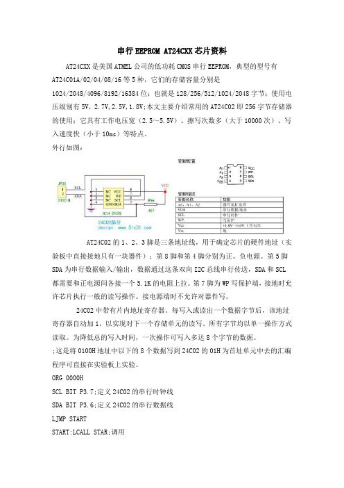
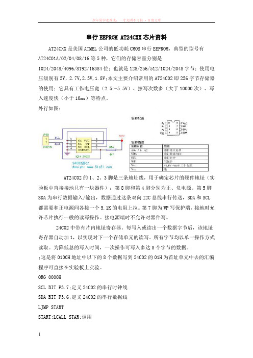
外行如图:AT24C02的1、2、3脚是三条地址线,用于确定芯片的硬件地址(实验板中直接接地只有一块器件);第8脚和第4脚分别为正、负电源。
第5脚SDA为串行数据输入/输出,数据通过这条双向I2C总线串行传送,SDA和SCL都需要和正电源间各接一个5.1K的电阻上拉。
第7脚为WP写保护端,接地时允许芯片执行一般的读写操作。
接电源端时不允许对器件写。
24C02中带有片内地址寄存器。
每写入或读出一个数据字节后,该地址寄存器自动加1,以实现对下一个存储单元的读写。
所有字节均以单一操作方式读取。
为降低总的写入时间,一次操作可写入多达8个字节的数据。
;这是将0100H地址中以下的8个数据写到24C02的01H为首址单元中去的汇编程序可直接在实验板上实验。
ORG 0000HSCL BIT P3.7;定义24C02的串行时钟线SDA BIT P3.6;定义24C02的串行数据线LJMP STARTSTART:LCALL STAR;调用MOV R2,#08H;一个数据有8位MOV DPTR,#0100H;定义源数据的位置LOOP:MOV A,#00HMOVC A,@A+DPTRLCALL SDATALCALL ACKJC LOOPINC DPTRDJNZ R2,LOOPLCALL STOP;调用停止子程序STAR:SETB SDASETB SCLNOPNOPNOPNOPCLR SDANOPNOPNOPNOPCLR SCLRETSDATA:MOV R0,#08HLOOP0:RLC AMOV SDA,CNOPNOPSETB SCLNOPNOPNOPCLR SCLDJNZ R0,LOOP0 RETACK:SETB SDA NOPNOPSETB SCL NOPNOPNOPNOPMOV C,SDA CLR SCLRETSTOP:CLR SDA NOPNOPNOPNOPSETB SCL NOPNOPNOPNOPSETB SDANOPNOPNOPRETORG 0100HDB 0A0H,10H,01H,02H,03H,04H,05H,06HEND读写子程序如下:;写串行E2PROM子程序XEPR; R3=10100000(命令1010+器件3位地址+读/写。
串行eepromat24cxx芯片资料
串行EEPROM AT24CXX芯片资料AT24CXX是美国ATMEL公司的低功耗CMOS串行EEPROM,典型的型号有AT24C01A/02/04/08/16等5种,它们的存储容量分别是1024/2048/4096/8192/16384位;也就是128/256/512/1024/2048字节;使用电压级别有5V,2.7V,2.5V,1.8V;本文主要介绍常用的AT24C02即256字节存储器的使用;它具有工作电压宽(2.5~5.5V)、擦写次数多(大于10000次)、写入速度快(小于10ms)等特点。
外行如图:AT24C02的1、2、3脚是三条地址线,用于确定芯片的硬件地址(实验板中直接接地只有一块器件);第8脚和第4脚分别为正、负电源。
第5脚SDA为串行数据输入/输出,数据通过这条双向I2C总线串行传送,SDA和SCL 都需要和正电源间各接一个5.1K的电阻上拉。
第7脚为WP写保护端,接地时允许芯片执行一般的读写操作。
接电源端时不允许对器件写。
24C02中带有片内地址寄存器。
每写入或读出一个数据字节后,该地址寄存器自动加1,以实现对下一个存储单元的读写。
所有字节均以单一操作方式读取。
为降低总的写入时间,一次操作可写入多达8个字节的数据。
;这是将0100H地址中以下的8个数据写到24C02的01H为首址单元中去的汇编程序可直接在实验板上实验。
ORG 0000HSCL BIT P3.7;定义24C02的串行时钟线SDA BIT P3.6;定义24C02的串行数据线LJMP STARTSTART:LCALL STAR;调用MOV R2,#08H;一个数据有8位MOV DPTR,#0100H;定义源数据的位置LOOP:MOV A,#00HMOVC A,@A+DPTRLCALL SDATALCALL ACKJC LOOPINC DPTRDJNZ R2,LOOPLCALL STOP;调用停止子程序STAR:SETB SDASETB SCLNOPNOPNOPNOPCLR SDANOPNOPNOPNOPCLR SCLRETSDATA:MOV R0,#08HLOOP0:RLC AMOV SDA,CNOPNOPSETB SCLNOPNOPNOPCLR SCLDJNZ R0,LOOP0 RETACK:SETB SDA NOPNOPSETB SCL NOPNOPNOPNOPMOV C,SDA CLR SCLRETSTOP:CLR SDA NOPNOPNOPNOPSETB SCL NOPNOPNOPNOPSETB SDANOPNOPNOPRETORG 0100HDB 0A0H,10H,01H,02H,03H,04H,05H,06HEND读写子程序如下:;写串行E2PROM子程序XEPR; R3=10100000(命令1010+器件3位地址+读/写。
EEPROM AT24C02 实验

EEPROM AT24C02 实验实验要求利用24C02 断电以后存储的数据不消失的特点,可以做一个断电保护装置。
首先利用单片机做一个0-99 秒的自动计时器。
然后随机关断电源,在通电以后计时器接着断电前的状态继续计时。
实验目的掌握IIC 总线工作原理及其操作方法,视频中有一讲专门讲IIC。
说明:首先简单的说明以下I2C 总线,I2C 总线是一种串行数据总线,只有二根信号线,一根是双向的数据线SDA,另一根是时钟线SCL。
在I2C 总线上传送的一个数据字节由八位组成。
总线对每次传送的字节数没有限制,但每个字节后必须跟一位应答位。
数据传送首先传送最高位(MSB)。
首先由主机发出启动信号“S”(SDA 在SCL 高电平期间由高电平跳变为低电平),然后由主机发送一个字节的数据。
启动信号后的第一个字节数据具有特殊含义:高七位是从机的地址,第八位是传送方向位,0 表示主机发送数据(写),1 表示主机接收数据(读)。
被寻址到的从机设备按传送方向位设置为对应工作方式。
标准I2C 总线的设备都有一个七位地址,所有连接在I2C 总线上的设备都接收启动信号后的第一个字节,并将接收到的地址与自己的地址进行比较,如果地址相符则为主机要寻访的从机,应答在第九位时钟脉冲时向SDA 线送出低电平作为应答。
除了第一字节是通用呼叫地址之外第二字节开始即数据字节。
数据传送完毕,由主机发出停止信号“P”(SDA 在SCL 高电平期间由低电平跳变为高电平)。
AT24C 系列串行E2PROM 具有I2C 总线接口功能,功耗小,宽电源电压(根据不同型号2.5V~6.0V),工作电流约为3mA,静态电流随电源电压不同为30μA~110μA。
由于I2C 总线可挂接多个串行接口器件,在I2C 总线中每个器件应有唯一的器件地址,按I2C 总线规则,器件地址为7 位数据(即一个I2C 总线系统中理论上可挂接128 个不同地址的器件),它和1 位数据方向位构成一个器件寻址字节,最低位D0 为方向位(读/写)。
ATMEL 24c02使用详解(汇编及C程序都有)

ATMEL 24c02使用详解原文地址: /Blog/cns!2FEAB5F0F11F7A67!296.entryATMEL 24c02使用详解I2C总线是一种用于IC器件之间连接的二线制总线。
它通过SDA(串行数据线)及SCL (串行时钟线)两根线在连到总线上的器件之间传送信息,并根据地址识别每个器件:不管是单片机、存储器、LCD驱动器还是键盘接口。
1.I2C总线的基本结构采用I2C总线标准的单片机或IC器件,其内部不仅有I2C 接口电路,而且将内部各单元电路按功能划分为若干相对独立的模块,通过软件寻址实现片选,减少了器件片选线的连接。
CPU不仅能通过指令将某个功能单元电路挂*或摘离总线,还可对该单元的工作状况进行检测,从而实现对硬件系统的既简单又灵活的扩展与控制。
I2C总线接口电路结构如图1所示。
2.双向传输的接口特性传统的单片机串行接口的发送和接收一般都各用一条线,如MCS51系列的TXD和RXD,而I2C总线则根据器件的功能通过软件程序使其可工作于发送或接收方式。
当某个器件向总线上发送信息时,它就是发送器(也叫主器件),而当其从总线上接收信息时,又成为接收器(也叫从器件)。
主器件用于启动总线上传送数据并产生时钟以开放传送的器件,此时任何被寻址的器件均被认为是从器件。
I2C总线的控制完全由挂接在总线上的主器件送出的地址和数据决定。
在总线上,既没有中心机,也没有优先机。
总线上主和从(即发送和接收)的关系不是一成不变的,而是取决于此时数据传送的方向。
SDA和SCL均为双向I/O线,通过上拉电阻接正电源。
当总线空闲时,两根线都是高电平。
连接总线的器件的输出级必须是集电极或漏极开路,以具有线“与”功能。
I2C总线的数据传送速率在标准工作方式下为100kbit/s,在快速方式下,最高传送速率可达400kbit/s。
3.I2C总线上的时钟信号在I2C总线上传送信息时的时钟同步信号是由挂接在SCL 时钟线上的所有器件的逻辑“与”完成的。
24C02 EEPROM存储器的C语言操作【范本模板】

#include 〈reg51。
h〉#ifndef false#define false 0#endif#ifndef true#define true 1#endif#define WriteDeviceAddress 0xa0#define ReadDviceAddress 0xa1sbit SDA = P3 ^ 5; //根据实际连接的管脚定义sbit SCL = P3 ^ 4;sbit led = P1^0;sbit led2 = P1^1;unsigned char code Num[21]={0xc0,0xf9,0xa4,0xb0,0x99,0x92,0x82,0xf8,0x80,0x90,0x40,0x79,0x24,0x30,0x19,0x12,0x02,0x78,0x00,0x10,0x89};unsigned char code Disdigit[4]= {0x7F,0xBF,0xDF,0xEF};unsigned char Disbuf[4];unsigned char code write_data[5] = { 5,2,5,1,8 };unsigned char read_data[5];//--—-————-—--——--—--—-—-——-—--—-—-——-—----——————-—-----———-——-—--————-—-———void Delayus(unsigned int number){for(;number!=0;number-—){}}//-—----—-----—---———--—-—--—----—--——----———-—--—--—--—--—----—---————--——-void DelayMs(unsigned int number){unsigned char temp;for(;number!=0;number——){for(temp=112;temp!=0;temp-—){}}}//—---————----—--—---——----———---—--——-——-----—-——--—---—---—--———-----——-——void Start(){SDA=1;Delayus(4);SCL=1;Delayus(4);SDA=0;Delayus(4);SCL=0;Delayus(4);}//---—-----—————--—-——---——---—-—-------—----—-—-——-——————---—--------------void Stop(){SCL=0;Delayus(4);SDA=0;Delayus(4);SCL=1;Delayus(4);SDA=1;Delayus(4);}//--—-—-————-—---—-——--———-—-———--———--——-————-—--———-————-—-———--————-—----void Ack(){SDA=0;Delayus(4);SCL=1;Delayus(4);SCL=0;Delayus(4);Delayus(4);}//—--——-—-———-——-—-—-—-——-——-——--————--—--—----—-——-—--———--—---————-———--——void NoAck(){SDA=1;Delayus(4);SCL=1;Delayus(4);SCL=0;Delayus(4);SDA=0;//}//-——----———-————————-—-—-——--—-——-—-——-—--—--—-———-——---—————-—----——-—--——bit TestAck(){bit ErrorBit;SDA=1;Delayus(4);SCL=1;Delayus(4);ErrorBit=SDA;Delayus(4);SCL=0;return(ErrorBit);}//-——-———-—-——--—-——----————-—-—--————-—-——-—-—---———————------——-—--—-—----void Write8Bit(unsigned char input){unsigned char temp;for(temp=8;temp!=0;temp-—){SDA=(bit)(input&0x80);Delayus(4);Delayus(4);SCL=0;Delayus(4);input=input〈〈1;}}//—-——--———----—-—-————--——---—---—---——---—-----——-——-——-————-—--—---———-—-unsigned char Read8Bit(){unsigned char temp,rbyte=0;for(temp=8;temp!=0;temp-—){SCL=1;Delayus(4);rbyte=rbyte<〈1;rbyte=rbyte|((unsigned char)(SDA));SCL=0;}return(rbyte);}void Write24c02(unsigned char *Wdata,unsigned char RomAddress,unsigned char number){Start();Write8Bit(WriteDeviceAddress);TestAck();Write8Bit(RomAddress);TestAck();for(;number!=0;number—-){Write8Bit(*Wdata);TestAck();Wdata++;}Stop();DelayMs(10);}void Read24c02(unsigned char *RamAddress,unsigned char RomAddress,unsigned char bytes){Start();Write8Bit(WriteDeviceAddress);TestAck();Write8Bit(RomAddress);TestAck();Start();Write8Bit(ReadDviceAddress);TestAck();while(bytes!=1){*RamAddress=Read8Bit();Ack();RamAddress++;bytes——;}*RamAddress=Read8Bit();NoAck();Stop();}void Display(void) //显示{unsigned int i = 0;unsigned int temp,count;temp = Disdigit[count];P2 =temp;temp = Disbuf[count];temp = Num[temp];P0 =temp;count++;if (count==4)count=0;}void time1() interrupt 3 using 2{Display();TH1 = (65535 - 2000)/256;TL1 = (65535 - 2000)%256;}void main(){TMOD = 0x15;TR1 = 1;EA = 1;ET1 = 1;Write24c02(write_data,0x00,3); DelayMs(200);Read24c02(read_data,0x00,4); while(1){Disbuf[0] = read_data[0];Disbuf[1]= read_data[1];Disbuf[2]= read_data[2];Disbuf[3] = read_data[3];}}。
24Cxx I2C EEPROM字节读写驱动程序

_nop_();_nop_();_nop_();_nop_();_nop_();_nop_(); //Thd:STA
SCL=0; //START
write_8bit(0xa0 | page); //写页地址和操作方式,对于24C32-24C256,page不起作用
ACK(ห้องสมุดไป่ตู้;
if(eepromtype>IIC24C16) //如果是24C01-24C16,地址为一字节;24C32-24C256,地址为二字节
调用方式:void WriteIIC_24CXX(enum EEPROMTYPE eepromtype,unsigned int address,unsigned char ddata) ﹫2001/09/18
函数说明:对于IIC芯片24CXX,在指定地址address写入一个字节ddata
SDA=0;
_nop_();_nop_();_nop_();_nop_();_nop_();_nop_(); //Thd:STA
SCL=0; //START
write_8bit( (address<<1) | 0x01); //写页地址和操作方式
ACK();
while (i--)
{
SDA=1;
#include "reg51.h"
#include "intrins.h"
sbit SCL= P2^7;
sbit SDA= P2^6;
enum EEPROMTYPE {IIC24C01,IIC24C01A,IIC24C02,IIC24C04,IIC24C08,IIC24C16,IIC24C32,IIC24C64,IIC24C128,IIC24C256};
at24c128程序范例
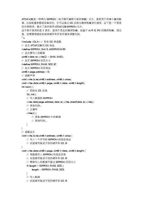
AT24C128是一种串行EEPROM(电可擦可编程只读存储器)芯片,通常用于存储小量的数据,比如配置参数或设备状态。
它可以通过I2C总线与微控制器进行通信。
以下是一个简单的示例程序,展示了如何使用AT24C128 EEPROM芯片。
这个例子使用的是C语言,适用于常见的微控制器,如基于AVR或PIC的微控制器。
请注意,你需要根据你的具体硬件和开发环境来调整代码。
```c#include <i2c.h> // 包含I2C库函数// 定义AT24C128的I2C地址#define EEPROM_SLAVE_ADDRESS 0x50// 定义要写入的数据uint8_t data_to_write[2] = {0x01, 0x02};// 定义EEPROM的页大小#define EEPROM_PAGE_SIZE 32// 定义EEPROM的页地址uint8_t page_address = 0;// 函数声明void write_byte(uint8_t address, uint8_t value);void write_data(uint8_t page, uint8_t *data, uint8_t length);int main() {// 初始化I2C总线i2c_init();// 写入数据到EEPROMwrite_data(page_address, data_to_write, sizeof(data_to_write));// 其他代码...// 主循环while(1) {// 读取EEPROM中的数据// 其他代码...}}// 函数定义void write_byte(uint8_t address, uint8_t value) {// 写入一个字节到EEPROM的指定地址// 实现细节取决于你的硬件和I2C库}void write_data(uint8_t page, uint8_t *data, uint8_t length) {// 将数据写入EEPROM的指定页面// 实现细节取决于你的硬件和I2C库// 确保写入的数据不超过EEPROM页的大小if (length > EEPROM_PAGE_SIZE) {length = EEPROM_PAGE_SIZE;}// 写入数据// 实现细节取决于你的硬件和I2C库}```请注意,这个示例程序是非常基础的,它没有包含错误检查和处理,也没有实现具体的I2C 通信细节。
24c02参考实例程序

{
Scl=0; _nop_();_nop_();_nop_();_nop_();_nop_(); Scl=1; _nop_();_nop_();_nop_();_nop_();_nop_(); if(Sda)
temp=temp|0x01; else
temp=temp&0xfe;
if(BitCounter-1) { temp1=temp<<1; temp=temp1; } BitCounter--; }
Ack();
*(PData+i)=Read();//读数据
Scl=0;
NoAck();
Stop();
}
}
/*------------------------------------------------
主程序
------------------------------------------------*/
sbit Sda=P1^2; sbit Scl=P1^1; sbit WP=P1^0;
//定义总线连接端口 //写保护,这里不使用
/*-----------------------------------------------延时程序
------------------------------------------------*/ void mDelay(unsigned char j) { unsigned int i; for(;j>0;j--) { for(i=0;i<125;i++) {;} } }
void main()
{
unsigned char Number[4]={0x06,0x5b,0x4f,0x66};// 显示码值 1234
- 1、下载文档前请自行甄别文档内容的完整性,平台不提供额外的编辑、内容补充、找答案等附加服务。
- 2、"仅部分预览"的文档,不可在线预览部分如存在完整性等问题,可反馈申请退款(可完整预览的文档不适用该条件!)。
- 3、如文档侵犯您的权益,请联系客服反馈,我们会尽快为您处理(人工客服工作时间:9:00-18:30)。
ATMEL公司24系列EEPROM编程举例作者:尘封往事文章来源:本站原创点击数:2043 更新时间:2006-1-12 13:07:34NAME Control_AT24Cxx; This collection of routines allows an AT89C2051 microcontroller to read ; and write the AT24Cxx family of serial CMOS EEPROMS. This version of the; code is compatible only with the AT89C2051 due to the location of the; data buffer and stack in RAM. The code may be modified to work with the; AT89C1051 by relocating or resizing the buffer and stack to fit into the; smaller amount of RAM available in the AT89C1051. Note that the minimum; size of the buffer is determined by the page size of the AT24Cxx.;; All five AT24Cxx device operations are supported. Byte Write, Current; Address Read and Random Read are implemented by the functions WRITE_BYTE, ; READ_CURRENT and READ_RANDOM, respectively. Page Write and Sequential Read ; are special cases of functions WRITE_BLOCK and READ_BLOCK, respectively.; WRITE_BLOCK and READ_BLOCK process from one byte to the number of bytes; in a page and transfer data between the AT24Cxx and the RAM buffer.;; The code supports multiple AT24Cxx devices per bus, each with a unique; address determined by the wiring of the address pins (A0, A1, A2). The; three-bit programmable address is passed to the WRITE_BYTE, READ_CURRENT, ; READ_RANDOM, WRITE_BLOCK and READ_BLOCK functions, where it is combined; with the AT24Cxx fixed address (FADDR) and used to address a device on the ; bus. Refer to the AT24Cxx family data sheets for additional information on ; device addressing.;; Functions BYTE_FILL, VERIFY_BYTE_FILL, PAGE_FILL and VERIFY_PAGE_FILL are ; artifacts from the debug process and serve to illustrate the use of the; device read and write functions with an AT24C64. To modify the code for a ; different member of the AT24Cxx family, simply redefine the values of SIZE ; (the number of bytes per device) and PSIZE (the number of bytes per page). ; To change the fill value, redefine FILL. To change the programmable portion ; of the device address, redefine PADDR to a value from zero to seven.;; The code meets all AT24Cxx family timing requirements when executed by an ; AT89Cx051 microcontroller with a 12 MHz clock. Code modifications may be; required if a faster clock is substituted.FADDR EQU 0a0h ; fixed address for AT24Cxx EEPROMsPADDR EQU 0 ; programmable address (0..7)SIZE EQU 2000h ; bytes per AT24C64PSIZE EQU 32 ; bytes per page for AT24C64FILL EQU 55h ; example fill value; Register definitions.index EQU r0 ; buffer pointerkount EQU r1 ; byte count registerzdata EQU r1 ; data registeraddr_lo EQU r2 ; 2-byte address registeraddr_hi EQU r3 ;; Microcontroller connections to AT24Cxx serial bus lines.SCL BIT p1.2 ; serial clockSDA BIT p1.3 ; serial dataDSEG AT 20HORG 40Hbuffer: DS PSIZE ; storage for read/write data ORG 60H ; stack originstack: DS 20H ; stack depthCSEGORG 0000H ; power on/reset vectorjmp on_resetORG 0003H ; external interrupt 0 vectorreti ; undefinedORG 000BH ; timer 0 overflow vectorreti ; undefinedORG 0013H ; external interrupt 1 vectorreti ; undefinedORG 001BH ; timer 1 overflow vectorreti ; undefinedORG 0023H ; serial I/O interrupt vectorreti ; undefinedORG 0080H ; begin code spaceUSING 0 ; register bank zeroon_reset:mov sp, #(stack-1) ; initialize stack pointer ; Initialize AT24Cxx serial bus lines.setb SDA ; highsetb SCL ; highcall byte_filljc faultcall verify_byte_filljc faultcall page_filljc faultcall verify_page_filljc faultfault:jmp $byte_fill:; Fill every byte in an AT24Cxx with the same value. ; Writes one address at a time (page mode is not used). ; Returns CY set to indicate write timeout.; Destroys A, B, DPTR, XDATA, ADDR_HI:ADDR_LO.mov zdata, #FILL ; set up fill datamov dptr, #0 ; initialize address pointerx51:mov addr_lo, dpl ; set up addressmov addr_hi, dph ;mov b, #120 ; retry counterx52:mov a, #PADDR ; programmable addresscall write_byte ; try to writejnc x53 ; jump if write OKdjnz b, x52 ; try againsetb c ; set timeout error flagjmp x54 ; exitx53:inc dptr ; advance address pointer; mov a, dpl ; check low byte; cjne a, #(LOW SIZE), x51 ; jump if not lastmov a, dph ; check high bytecjne a, #(HIGH SIZE), x51 ; jump if not lastclr c ; clear error flagx54:retverify_byte_fill:; Verify that all bytes in an AT24Cxx match a fill value.; Reads and verifies one byte at a time (page mode is not used). ; Performs a Random Read function to initialize the internal ; address counter and checks the contents of the first address. ; Then performs multiple Current Address Read functions to step ; through the remaining addressess.; Returns CY set to indicate read timeout or compare fail.; Destroys A, B, DPTR.mov dptr, #0 ; initialize address pointer/counter mov addr_lo, dpl ; set up addressmov addr_hi, dph ;mov b, #120 ; retry counterx81:mov a, #PADDR ; programmable addresscall read_random ; try to readjnc x82 ; jump if read OKdjnz b, x81 ; try againjmp x86 ; set error flag and exitx82:cjne a, #FILL, x86 ; jump if compare errorjmp x85 ; do remaining addressesx83:mov a, #PADDRcall read_currentjc x87 ; jump if read failscjne a, #FILL, x86 ; jump if compare errorx85:inc dptr ; advance address pointermov a, dph ; check high bytecjne a, #(HIGH SIZE), x83 ; jump if not lastclr c ; clear error flagjmp x87 ; exitx86:setb c ; set error flagx87:retpage_fill:; Fill every byte in an AT24Cxx with the same value. ; Writes one page at a time.; Returns CY set to indicate write timeout.; Destroys A, B, DPTR, KOUNT, INDEX, ADDR_HI:ADDR_LO. ; First fill buffer.mov b, #PSIZE ; bytes per pagemov index, #buffer ; point to bufferx61:mov @index, #FILL ; put fill value in bufferinc index ; advance pointerdjnz b, x61 ; next byte; Copy buffer to device, one page at a time.mov dptr, #0 ; initialize address pointerx62:mov addr_lo, dpl ; set up addressmov addr_hi, dph ;mov kount, #PSIZE ; bytes per pagemov b, #120 ; retry counterx63:mov a, #PADDR ; programmable addresscall write_block ; try to writejnc x64 ; jump if write OKdjnz b, x63 ; try againsetb c ; set timeout error flagjmp x66 ; exitx64:; Add page size to address pointer.mov a, dpl ; get low byteadd a, #PSIZE ; add page sizemov dpl, a ; save low bytejnc x65 ; jump if high byte not affectedinc dph ; increment high bytex65:; cjne a, #(LOW SIZE), x62 ; jump if low byte not lastmov a, dph ; check high bytecjne a, #(HIGH SIZE), x62 ; jump if not lastclr c ; clear error flagx66:retverify_page_fill:; Verify that all bytes in an AT24Cxx match a fill value. ; Reads and verifies one page at a time.; Returns CY set to indicate read timeout or compare fail. ; Destroys A, B, DPTR, KOUNT, INDEX, ADDR_HI:ADDR_LO.; Copy device page to buffer.mov dptr, #0 ; initialize address pointerx71:mov addr_lo, dpl ; set up addressmov addr_hi, dph ;mov kount, #PSIZE ; bytes per pagemov b, #120 ; retry counterx72:mov a, #PADDR ; programmable addresscall read_block ; try to readjnc x74 ; jump if read OKdjnz b, x72 ; try againx73:setb c ; set error flagjmp x77 ; exitx74:; Verify buffer contents.mov b, #PSIZE ; bytes per pagemov index, #buffer ; point to bufferx75:cjne @index, #FILL, x73 ; jump if compare failsinc index ; advance pointerdjnz b, x75 ; next byte; Add page size to address pointer.mov a, dpl ; get low byteadd a, #PSIZE ; add page sizemov dpl, a ; save low bytejnc x76 ; jump if high byte not affectedinc dph ; increment high bytex76:; cjne a, #(LOW SIZE), x71 ; jump if low byte not last mov a, dph ; check high bytecjne a, #(HIGH SIZE), x71 ; jump if not lastclr c ; clear error flagx77:retwrite_block:; Write from one byte to one page of data to an AT24Cxx.; Called with programmable address in A, address of first byte ; in register pair ADDR_HI:ADDR_LO, data in BUFFER, byte count ; in register KOUNT.; Does not wait for write cycle to complete.; Returns CY set to indicate that the bus is not available ; or that the addressed device failed to acknowledge.; Destroys A, KOUNT, INDEX.call startjc x38 ; abort if bus not availablerl a ; programmable address to bits 3:1orl a, #FADDR ; add fixed addressclr acc.0 ; specify write operationcall shout ; send device addressjc x37 ; abort if no acknowledgemov a, addr_hi ; send high byte of addresscall shout ;jc x37 ; abort if no acknowledgemov a, addr_lo ; send low byte of addresscall shout ;jc x37 ; abort if no acknowledgemov index, #buffer ; point to bufferx36:mov a, @index ; get datacall shout ; send datajc x37 ; abort if no acknowledgeinc index ; advance buffer pointerdjnz kount, x36 ; next byteclr c ; clear error flagx37:call stopx38:retread_block:; Read from one byte to one page of data from an AT24Cxx.; Performs a Random Read which is extended into a Sequential Read ; when more than one byte is read. Called with programmable address ; in A, address of first byte in register pair ADDR_HI:ADDR_LO,; byte count in register KOUNT.; Returns data in BUFFER. Returns CY set to indicate that the bus is ; not available or that the addressed device failed to acknowledge. ; Destroys A, KOUNT, INDEX.; Send dummy write command to address first byte.call startjc x35 ; abort if bus not availablerl a ; programmable address to bits 3:1orl a, #FADDR ; add fixed addressmov index, a ; save copy of device address clr acc.0 ; specify write operationcall shout ; send device addressjc x34 ; abort if no acknowledgemov a, addr_hi ; send high byte of address call shout ;jc x34 ; abort if no acknowledgemov a, addr_lo ; send low byte of address call shout ;jc x34 ; abort if no acknowledge; Send read command and receive data.call start ; second start for readjc x34 ; abort if bus not availablemov a, index ; get device addresssetb acc.0 ; specify read operationcall shout ; send device addressjc x34 ; abort if no acknowledgemov index, #buffer ; point to bufferx31:call shin ; receive data bytemov @index, a ; save datacjne kount, #1, x32 ; jump if not last byte call NAK ; do not acknowledge last bytejmp x33 ; donex32:call ACK ; acknowledge byteinc index ; advance buffer pointerdjnz kount, x31 ; next bytex33:clr c ; clear error flagx34:call stopx35:retwrite_byte:; AT24Cxx Byte Write function.; Called with programmable address in A, byte address in ; register pair ADDR_HI:ADDR_LO, data in register XDATA. ; Does not wait for write cycle to complete.; Returns CY set to indicate that the bus is not available ; or that the addressed device failed to acknowledge.; Destroys A.call startjc x49 ; abort if bus not availablerl a ; programmable address to bits 3:1orl a, #FADDR ; add fixed addressclr acc.0 ; specify write operationcall shout ; send device addressjc x48 ; abort if no acknowledgemov a, addr_hi ; send high byte of addresscall shout ;jc x48 ; abort if no acknowledgemov a, addr_lo ; send low byte of addresscall shout ;jc x48 ; abort if no acknowledgemov a, zdata ; get datacall shout ; send datajc x48 ; abort if no acknowledgeclr c ; clear error flagx48:call stopx49:retread_current:; AT24Cxx Current Address Read function.; Called with programmable address in A. Returns data in A. ; Returns CY set to indicate that the bus is not available ; or that the addressed device failed to acknowledge.call startjc x45 ; abort if bus not availablerl a ; programmable address to bits 3:1orl a, #FADDR ; add fixed addresssetb acc.0 ; specify read operationcall shout ; send device addressjc x44 ; abort if no acknowledgecall shin ; receive data bytecall NAK ; do not acknowledge byteclr c ; clear error flagx44:call stopx45:retread_random:; AT24Cxx Random Read function.; Called with programmable address in A, byte address in ; register pair ADDR_HI:ADDR_LO. Returns data in A.; Returns CY set to indicate that the bus is not available ; or that the addressed device failed to acknowledge.push bmov b, a ; save copy of programmable address; Send dummy write command to set internal address.call startjc x47 ; abort if bus not availablerl a ; programmable address to bits 3:1orl a, #FADDR ; add fixed addressclr acc.0 ; specify write operationcall shout ; send device addressjc x46 ; abort if no acknowledgemov a, addr_hi ; send high byte of addresscall shout ;jc x46 ; abort if no acknowledgemov a, addr_lo ; send low byte of addresscall shout ;jc x46 ; abort if no acknowledge; Call Current Address Read function.mov a, b ; get programmable addresscall read_currentjmp x47 ; exitx46:call stopx47:pop bretstart:; Send START, defined as high-to-low SDA with SCL high. ; Return with SCL, SDA low.; Returns CY set if bus is not available.setb SDAsetb SCL; Verify bus available.jnb SDA, x40 ; jump if not highjnb SCL, x40 ; jump if not highnop ; enforce setup delay and cycle delayclr SDAnop ; enforce hold delaynop ;nop ;nop ;nop ;clr SCLclr c ; clear error flagjmp x41x40:setb c ; set error flagx41:retstop:; Send STOP, defined as low-to-high SDA with SCL high. ; SCL expected low on entry. Return with SCL, SDA high. clr SDAnop ; enforce SCL low and data setupnopsetb SCLnop ; enforce setup delaynop ;nop ;nop ;nop ;setb SDAretshout:; Shift out a byte to the AT24Cxx, most significant bit first. ; SCL, SDA expected low on entry. Return with SCL low.; Called with data to send in A.; Returns CY set to indicate failure by slave to acknowledge. ; Destroys A.push bmov b, #8 ; bit counterx42:rlc a ; move bit into CYmov SDA, c ; output bitnop ; enforce SCL low and data setupsetb SCL ; raise clocknop ; enforce SCL highnop ;nop ;nop ;clr SCL ; drop clockdjnz b, x42 ; next bitsetb SDA ; release SDA for ACKnop ; enforce SCL low and tAAnop ;setb SCL ; raise ACK clocknop ; enforce SCL highnop ;nop ;nop ;mov c, SDA ; get ACK bitclr SCL ; drop ACK clockpop bretshin:; Shift in a byte from the AT24Cxx, most significant bit first. ; SCL expected low on entry. Return with SCL low.; Returns received data byte in A.setb SDA ; make SDA an inputpush bmov b, #8 ; bit countx43:nop ; enforce SCL low and data setupnop ;nop ;setb SCL ; raise clocknop ; enforce SCL highnop ;mov c, SDA ; input bitrlc a ; move bit into byteclr SCL ; drop clockdjnz b, x43 ; next bitpop bretACK:; Clock out an acknowledge bit (low).; SCL expected low on entry. Return with SCL, SDA low.clr SDA ; ACK bitnop ; enforce SCL low and data setupnop ;setb SCL ; raise clocknop ; enforce SCL highnop ;nop ;nop ;clr SCL ; drop clockretNAK:; Clock out a negative acknowledge bit (high).; SCL expected low on entry. Return with SCL low, SDA high. setb SDA ; NAK bitnop ; enforce SCL low and data setupnop ;setb SCL ; raise clocknop ; enforce SCL high nop ;nop ;nop ;clr SCL ; drop clockretEND。