惠普M1005打印机的拆装(很详细)
惠普M1005换定影器(加热组件)超详细图解

惠普M1005换定影器(加热组件)超详细图解遇到打印出来的文件,字体有像毛一样,用手一搓就掉,一般是定影器出问题了,换吧。
在淘宝上买个。
准备工作:一字十字镙丝刀各一把。
1、先拆这个托纸板,方便后面拆机器。
2、再拆下面的装纸的,镙丝刀顶一下,拉出来就行了:3、转过背面,拆背面三颗镙丝,就可以拆掉两边的灰色边盖,再拆下背面塑料和铁挡板。
两边挡盖拆出来:4、拆背面这两块塑料和铁挡板,用手抬一下,就出来了。
5、拆扫描组件。
拆扫描组件,我是先拆图下两个传感支臂:接着拆扫描组件数据线,数据线在打印机正面右边:拨出数据线后,再拆下下图中连着卡鼓的齿轮的这个组件:拆出这白色零件,扫描组件打开90度角,不要打太开,会拉伤数据线,拧下保护数据线镙丝和保护锡纸,拆数据线,拆下扫描组件:扫描组件拆出来了,才可以把下面这个组件拆出来。
6、拆前面的挡板:7、拆这片灰色的组件了,叫什么,我不知道:)~~8、开始拆定影器,先拆下图这个支架:再拆传感器,拆这个组件前先把连着的线都拨出来:拆线:拆传感器:拧下下图位置3颗镙丝,拆定影器:9、安装新的定影器:下图排序是从上到下,从左到右,往回装就行了。
中间那红色的组件,我是后面拆的,感觉先拆,要方便些,所以开头就改成先拆这两个家伙了~~10、安装新定影器:这两组件,最好用原来的装上去:装上新定影器,上好3颗镙丝,先装下图这个零件再装感应器:装好线:后面的就怎么拆的,怎么装回去,下图提示传感支臂的安装方法:按这个角度放上去就行了。
11、装上背面两个塑料和铁挡板,最后装上旁边两个挡盖,完工。
。
HPM1005更换部件拆机图解(英文版)
HPM1005更换部件拆机图解(英⽂版)6Removal and replacementThis chapter provides information about the following topics.●Removal and replacement strategyENWW59Removal and replacement strategyNOTE Some photos show a device other than the HP LaserJet M1005 MFP. Repair andreplacement procedures in this chapter are for the HP LaserJet M1005 MFP and are not affectedby cosmetic differences (for example, the color of the covers) shown in these photos.This chapter documents the removal and replacement of field replaceable parts (FRUs) only.Reinstallation is generally the reverse of removal. Occasionally, notes and hints are included to provide directions for difficult or critical replacement procedures.AdmonitionsWARNING!Unplug the power cord from the power outlet (at the wall receptacle) beforeattempting to service the device. It this warning is not followed, severe injury can result. Certainfunctional checks during troubleshooting must be performed with power supplied to the device.However, the power supply should be disconnected during removal.Sheet-metal and plastic edges in the device can be sharp. Use caution when servicing this device.Never operate or service the device with the protective cover removed from the laser/scannerassembly. The invisible reflected beam can damage your eyes.CAUTION The device contains components that are sensitive to electrostatic discharge (ESD).Always perform service work at an ESD-protected workstation. If an ESD-protected workstationis not available, discharge body static by grasping the print engine chassis before touching anESD-sensitive component. Ground the print engine chassis before servicing the device.CAUTION Do not bend or fold the FFCs during the removal or reinstallation process.NOTE For service purposes, the upper part of the HP LaserJet M1005 MFP is, in effect, the"scanner" and the lower part is the "printer". Together, they also act as a photocopier, but theservice description here is simplified by referring to copier functionality only when specificallynecessary.Tip To install a self-tapping screw, first turn it counterclockwise to align it with the existing threadpattern, then carefully turn it clockwise to tighten. Do not overtighten.Required tools●#2 Phillips screwdriver with magnetic tip●Small flat-blade screwdriver●#8 and #10 torx screwdrivers●Needle-nose pliers●ESD mat (if available)●Penlight (optional)●Long flat-blade screwdriver (optional)60Chapter 6 Removal and replacement ENWWCAUTION Do not use a pozidrive screwdriver or any motorized screwdriver. These can damagescrews or screw threads on the device.Before performing service●If possible, print a configuration page (to record customer settings) and menu structure report.See Troubleshooting tools on page 140.●Remove all media from the device and remove the media input tray. See Media input trayon page 78.●Turn off the power by using the power switch.●Unplug the power cord from the wall receptacle.●Place the device on an ESD mat, if available. If an ESD-protected workstation is not available,discharge body static and ground the print engine chassis before servicing the device.●Remove the print cartridge.After performing service●Replace the print cartridge.●Reload the input tray with media.●Restore customer configuration settings.Parts removal orderUse the following diagrams to determine which parts of the device must be removed before servicing. ENWW Removal and replacement strategy61Control panel overlayControl panelScanner lidScanner assemblyLink assembly and scanner springPrinter separation padPrint cartridgePrinter pickup rollerTransfer rollerMedia input trayPrinter side coversRear cover and fuser coverPower supplyScanner assemblyPrint-cartridge doorFront coverScanner support frameEngine controller unitLaser/scanner assemblyMain motorFuser assemblyPaper pickup assemblyFront coverFormatterFigure 6-1 Parts removal order for the HP LaserJet M1005 MFP62Chapter 6 Removal and replacement ENWWFlatbed lid1.Open the flatbed lid.2.Lift the lid up and off of the scanner assembly to remove it.NOTE The lid must be in the fully opened position to release the hinge pins from the hinge brackets.Figure 6-2 Remove the flatbed lid (1 of 2)Tip When the flatbed lid is reinstalled, make sure that the hinge pins are fully seated inthe hinge brackets on the scanner flatbed assembly.ENWW Removal and replacement strategy63Control-panel overlayUse a small flat blade screwdriver to lift up the control-panel overlay and then remove it.CAUTION Be careful to not damage the overlay if it will be reinstalled after servicing the device.Figure 6-3 Remove the control-panel overlay64Chapter 6 Removal and replacement ENWWControl panelTip Lift up the control-panel overlay to see the screw. See Control-panel overlay on page 64.Figure 6-4 Remove the control panel (1 of 4)1.Remove one screw.Figure 6-5 Remove the control panel (2 of 4)ENWW Removal and replacement strategy652.Slide the control panel toward you and slightly lift up the control panel.Figure 6-6 Remove the control panel (3 of 4)3.Disconnect one flat flexible cable (callout 1) and remove the control panel.Figure 6-7 Remove the control panel (4 of 4)Tip When reinstalling the control panel, make sure the rear mounting tabs on the bottom rear of the control panel engage the holes in the scanner assembly, and then slide the control panel toward the rear of the device.66Chapter 6 Removal and replacement ENWWScanner assembly1.Remove the flatbed lid. See Flatbed lid on page 63.2.Remove one screw (callout 1).Figure 6-8 Remove the scanner assembly (1 of 11)3.Gently pry the side cover away from the device chassis.Figure 6-9 Remove the scanner assembly (2 of 11)ENWW Removal and replacement strategy674.Release the side cover bottom locking tab and remove the cover.Figure 6-10 Remove the scanner assembly (3 of 11)5.Disconnect two FFCs (callout 2).Figure 6-11 Remove the scanner assembly (4 of 11)68Chapter 6 Removal and replacement ENWW6.Push the print-cartridge-door button and raise the scanner assembly.Figure 6-12 Remove the scanner assembly (5 of 11)7.Remove the shield and the FFCs from the guide (callout 3).NOTE The screw (callout 4) that fastens the shield to the device chassis does not needto be removed.Figure 6-13 Remove the scanner assembly (6 of 11)ENWW Removal and replacement strategy698.Release the tab on the gear-drive arm bracket and carefully flex it away from the scanner assembly.Figure 6-14 Remove the scanner assembly (7 of 11)9.Pull the bracket toward the right side of the device until its mounting tabs clear the holes in thescanner assembly.Figure 6-15 Remove the scanner assembly (8 of 11)70Chapter 6 Removal and replacement ENWW/doc/e46440e0856a561252d36f48.html e a small flat-blade screwdriver to release the hinge tabs on each front hinge (right side shown).WARNING!When the front hinges are disengaged, the scanner assembly can easily falloff of the device base if it is rotated too far toward the back of the product.CAUTION Do not push too hard on the link tabs or the tabs might break.Figure 6-16 Remove the scanner assembly (9 of 11)11.Remove the hinges (right side shown).Figure 6-17 Remove the scanner assembly (10 of 11)ENWW Removal and replacement strategy7112.Rotate the scanner assembly toward the rear of the product until the rear hinges clear the chassis hinge pins. Lift the scanner assembly up and off of the device base.Figure 6-18 Remove the scanner assembly (11 of 11)72Chapter 6 Removal and replacement ENWWDevice separation padNOTE Some photos show a device other than the HP LaserJet M1005 MFP. Repair and replacement procedures in this chapter are for the HP LaserJet M1005 MFP and are not affected by cosmetic differences (for example, the color of the covers) shown in these photos.1.At the back of the device, remove two screws (callout 1).Figure 6-19 Remove the device separation pad (1 of 2)2.Remove the device separation pad and frame.Figure 6-20 Remove the device separation pad (2 of 2)ENWW Removal and replacement strategy73Print cartridgeCAUTION To prevent damage, do not expose the print cartridge to direct or bright light. Cover it with a piece of paper.1.Push the print-cartridge-door button to release the print-cartridge door.Figure 6-21 Remove the print cartridge (1 of 2)2.Pull the print cartridge up and out of the device.Figure 6-22 Remove the print cartridge (2 of 2)74Chapter 6 Removal and replacement ENWWDevice pickup roller1.Remove the print cartridge and locate the device pickup roller. See Print cartridge on page 74.Figure 6-23 Remove the device pickup roller (1 of 5)2.Gently release the small, white tabs on each side of the pickup roller by pushing them away fromthe roller, and then rotate the roller away from the mounting frame.CAUTION Do not touch the black-sponge transfer roller inside the device. Touching the transfer roller can damage the device.Use gentle pressure to release the small white tabs to avoid breaking them.Figure 6-24 Remove the device pickup roller (2 of 5)ENWW Removal and replacement strategy753.Gently pull the roller up and out of the device.Figure 6-25 Remove the device pickup roller (3 of 5)4.Circular and rectangular pegs on each side of the pickup roller fit into corresponding slots on the pickup-roller mounting frame to prevent the roller from being incorrectly installed. Position the replacement pickup roller in the slots on the pickup-roller frame.Figure 6-26 Remove the device pickup roller (4 of 5)76Chapter 6 Removal and replacement ENWW5.Rotate the top of the pickup roller into position until the white tabs on each side of the roller snap into place.Figure 6-27 Remove the device pickup roller (5 of 5)ENWW Removal and replacement strategy77。
部分惠普打印机一体机拆机方法

部分惠普打印机/一体机拆机方法一、2128(1)将四颗螺丝拧开,如图1所示。
将整个机器上盖拆下。
拆下上盖时应注意慢抬,以免损伤机器内的控制面板及扫描组件与主板的连接线,如图2所示。
图1图2(2)拆除图3上所示的六颗螺丝,便可以拆下笔架,拆除时应注意笔架与主板的连接线。
如图3所示。
图3(3)将后挡纸板取下,拆下最右边的清洁单元,然后拧下中间的螺丝和左边的卡子,便可以拆除整个进纸单元。
如图4所示。
图4(4)拧下螺丝,拆除马达,便可以取下主板。
如图5所示。
图5(5)取下整个玻璃板,便可以拆下扫描头组件,取下玻璃板时应注意控制面板下的数据线。
如图6所示。
图6二、3508/3608(1)将图1所示的控制面板按图2所示的黄色箭头方向打开。
图1图2(2)将图3中红圈中的螺丝拧下来,取下话筒下边的盖子。
图3 (3)拧下图4中2个红圈处的螺丝。
图4 (4)将图5中3个孔处的螺丝拧下来。
图5(5)将图6中红圈处的螺丝拧下来,并把后挡板按图6中黄色箭头的方向取下来,就可以拿下中间的壳了。
图6(6)拔掉图7、图8中所示的各连接到板上的数据线。
图6图7(7)把固定板的螺丝拧下来,就可以把板取下来了。
如图8红圈所示。
图8(8)将图9红圈处的铁板取下来,取下时要小心两边的卡子。
图9(9)将扫描组件取下来的时候注意图10中两个红圈处的卡子。
图10 (10)然后即可拆卸机器。
如图11、图12所示。
图11图12打印机下半部分的拆卸方法参见DJ3000系列。
如图13所示。
图13三、5328(1)取下机器的白色外盖。
如图1、图2所示。
图1将这个白色的盖取下来图2(2)将控制面板的外盖取下来。
如图3、图4所示。
图3图4(3)将图5中红圈处的2个小堵塞物拿下来,这里有2颗螺丝。
图5(4)将2颗螺丝拧下来,就可以取下控制面板了。
如图6所示。
图6(5)将固定侧盖的螺丝拧下来。
如图7所示。
图7(6)取下侧盖时注意机器低部的卡子。
如图8所示。
图8(7)取下白色的盖子。
惠普M1005打印机的拆装[很详细]
![惠普M1005打印机的拆装[很详细]](https://img.taocdn.com/s3/m/fae1fc04647d27284b73519d.png)
用的就是12A的鼓,就是第一篇加粉的那个鼓
打开盖子
这是用来开关的,左边一个,右边一个
首先就是擦下这个,看见上面那个卡口没有
往上顶一下,就可以下下来了
然后是卡最上面那个板子的,连着卡鼓的齿轮。
右边往下按,往右就可以抽出来
在来下后背
看见那3个螺丝,下下来后,双手托着下面,抬一下,就可以拿下来
这是连着面板的2条线
一条黑的,一条白的
在来下侧盖,看见下面的那个卡口了吧,顶一下,在来扒上面的就很轻松
下来了
这边是管面板的
轻轻一抽就可以了,从这里拿出来
上面第二层盖子一翻就开了
这是卡全面口子的
先把这按下去,在从上左右2边往上拉,一起用劲往后抽就出来了
把这边的线全部抽掉
就是这样了
下左边2个螺丝,右边一个
往上一拉就出来了。
惠普hp2025打印机的转印带怎么拆解?

惠普hp2025打印机的转印带怎么拆解?
作者:oa161商务办公网
hp2025的打印机的转印组件的拆解共四个过程,它是从前面拆出来的,衔接的电源线也在前面。
1、首要面临机器的正面(有开关和面板显现菜单的一面),翻开机器前盖,拿出4个硒鼓。
最重要的是拿出装硒鼓的架子,硒鼓架子的右侧快拉出来的当地有个暗扣,拿小一向螺丝刀从架子和面板的缝隙伸过去反着翘,当心拉出架子。
(这个当地当心点,别翘断了,我是把面板也拆了才看到这个小机关的)。
2、拿掉纸盒,可看到有一板,往下一搬,即是从下面去卡纸的板。
翻开打印机后盖,注意看定影器下面有一塑料架子上有黄色标签,有个箭头是向前推的指示,如今别推,等下拆了前面螺丝再推。
可试试看,拿起转印组件的后边两个角,能够轻松的向上抬必定间隔的。
ok,等下步做完再推。
3、在打印机前面拆硒鼓架子后能够看到转印组件出左右有两螺丝,松开,转印带的线就在下面,拔掉右边的线头,左面的能够不拔,但这个小架子要拆松。
4、如今能够试着渐渐抬转印组件的前面两个角,向上提一提,向前就能够顺畅拉出了,轻拉,别用蛮力,不可的话,在打印机后部的转印组件左右两个角向上提提,往前推推,顺着导轨就能出来了,这样hp2025转印带组件就拆出来了。
hp1005的拆装(很详细)

用的就是12A的鼓,就是第一篇加粉的那个鼓
打开盖子
这是用来开关的,左边一个,右边一个
首先就是擦下这个,看见上面那个卡口没有
往上顶一下,就可以下下来了
然后是卡最上面那个板子的,连着卡鼓的齿轮。
右边往下按,往右就可以抽出来
在来下后背
看见那3个螺丝,下下来后,双手托着下面,抬一下,就可以拿下来这是连着面板的2条线
一条黑的,一条白的
在来下侧盖,看见下面的那个卡口了吧,顶一下,在来扒上面的就很轻松
下来了
这边是管面板的
轻轻一抽就可以了,从这里拿出来
上面第二层盖子一翻就开了
这是卡全面口子的
先把这按下去,在从上左右2边往上拉,一起用劲往后抽就出来了
把这边的线全部抽掉
就是这样了
下左边2个螺丝,右边一个
往上一拉就出来了。
m105墨泵更换教程

m105墨泵更换教程
1、更换墨盒之前我们需要购买好匹配的惠普M1005墨盒,因为不匹配的墨盒是无法使用的,一般在网上或者惠普官网都可以买到。
2、更换墨盒的时候,注意要先将打印机断电,然后打开打印机前段的外壳,我们就可以看到墨盒部分。
3、轻轻取下旧墨盒,然后对准墨盒接口装到打印机上,然后再盖上打印机前段的外壳。
4、墨盒安装完成之后,我们还需要测试一下打印机是否可以正常工作,检查打印是否清晰,确认无误后就完成了墨盒的更换工作。
HP惠普M1005定影组件拆解
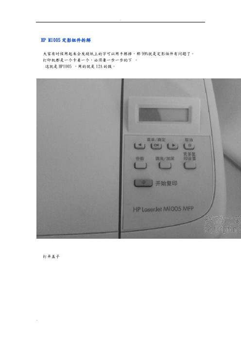
HP M1005定影组件拆解
大家有时候用起来会发现纸上的字可以用手擦掉,那99%就是定影组件有问题了。
打印机都是一个卡着一个,必须要一步一步的下。
这就是HP1005 ,用的就是12A的鼓。
打开盖子
这是用来开关的,左边一个,右边一个
首先就是擦下这个,看见上面那个卡口没有
往上顶一下,就可以下下来了
然后是卡最上面那个板子的,连着卡鼓的齿轮。
右边往下按,往右就可以抽出来
在来下后背
看见那3个螺丝,下下来后,双手托着下面,抬一下,就可以拿下来这是连着面板的2条线
一条黑的,一条白的
在来下侧盖,看见下面的那个卡口了吧,顶一下,在来扒上面的就很轻松
下来了
这边是管面板的
轻轻一抽就可以了,从这里拿出来
上面第二层盖子一翻就开了
这是卡全面口子的
先把这按下去,在从上左右2边往上拉,一起用劲往后抽就出来了
把这边的线全部抽掉
就是这样了
下左边2个螺丝,右边一个
往上一拉就出来了
还有定影组件的拆解,如果大家需要,我在发出来!。
- 1、下载文档前请自行甄别文档内容的完整性,平台不提供额外的编辑、内容补充、找答案等附加服务。
- 2、"仅部分预览"的文档,不可在线预览部分如存在完整性等问题,可反馈申请退款(可完整预览的文档不适用该条件!)。
- 3、如文档侵犯您的权益,请联系客服反馈,我们会尽快为您处理(人工客服工作时间:9:00-18:30)。
用的就是12A的鼓,就是第一篇加粉的那个鼓
打开盖子
这是用来开关的,左边一个,右边一个
首先就是擦下这个,看见上面那个卡口没有
往上顶一下,就可以下下来了
然后是卡最上面那个板子的,连着卡鼓的齿轮。
右边往下按,往右就可以抽出来
在来下后背
看见那3个螺丝,下下来后,双手托着下面,抬一下,就可以拿下来
这是连着面板的2条线
一条黑的,一条白的
在来下侧盖,看见下面的那个卡口了吧,顶一下,在来扒上面的就很轻松
下来了
这边是管面板的
轻轻一抽就可以了,从这里拿出来
上面第二层盖子一翻就开了
这是卡全面口子的
先把这按下去,在从上左右2边往上拉,一起用劲往后抽就出来了
把这边的线全部抽掉
就是这样了
下左边2个螺丝,右边一个
往上一拉就出来了。