Vigor 路由器中文使用手册
Vigor Pro5510C产品参数介绍(中文)
Draytek VigorPro5510C 系列产品具有统一威胁管理(UTM)功能的整合型网络安全设备中小企业(SMB)安全网络防护的新纪元¾高性能的安全功能¾独有的MSSI(Multi-Stack Stateful Inspection)专利技术加速¾阻挡间谍软件,网络钓鱼,病毒和垃圾邮件的攻击¾即时通信(IM),P2P(点到点)应用更细粒度的控制(CSM)¾URL、WEB 过滤¾免费的网站分类过滤产品优势:统一威胁管理(UTM)是网络安全发展的新趋势依靠单一防火墙就足以将攻击者阻挡在公司网络之外已成为历史,而统一威胁管理(UTM)则是网络安全应用市场上的最新趋势。
站在技术前沿,Draytek VigorPro5510C系列产品通过MSSI(Multi-Stack Stateful Inspection)专利技术,这项新技术引进了全新的多合一网络安全设备,它提供内容过滤,反病毒,反垃圾邮件以及入侵检测这些传统意义上需要多台设备提供的功能。
高性能All-in-one一体化设计从商业前景来看,IT管理人员都应当以“企业级规划”考虑广泛的安全问题。
他们现在能够利用all-in-one一体化设备提供坚实的防护和高性能, UTM解决方案。
下面所有功能被整合在一台设备里面,并且通过简单的统一界面进行管理:反病毒、入侵检测与保护、反垃圾邮件、防火墙、虚拟私有网(VPN)、负载均衡、带宽管理(QOS)和URL、内容过滤(WEB)。
硬件加速的内容处理器VigorPro系列产品将一个硬件加速的内容处理器集成在设备中,以提高检测过程中字串匹配的速度。
因此,作为一款入线式安全设备,VigorPro5510C才在保证良好的传输性能的同时,实时地保护整个网络不受病毒、入侵或是恶意软件的伤害。
MSSI(Multi-Stack Stateful Inspection)专利技术基于MSSI核心技术,VigorPro5510C不仅可以通过防入侵检测出蠕虫攻击,还能够检测出压缩文件或是MIME电子邮件中的病毒,而且不受文件大小限制。
如何将Vigor 路由器恢复至出厂默认设置
如何将Vigor 路由器恢复至出厂默认设置?不同型号的Vigor路由器有不同的方法来恢复出厂值。
请参考以下三种方法。
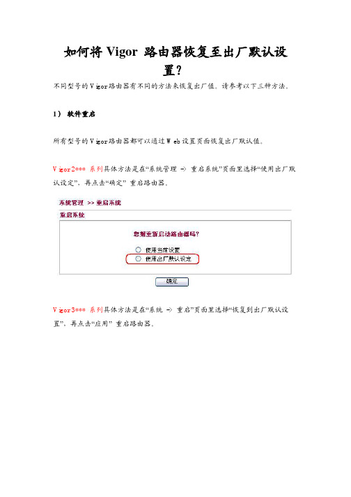
1)软件重启所有型号的Vigor路由器都可以通过Web设置页面恢复出厂默认值。
Vigor 2*** 系列具体方法是在“系统管理-> 重启系统”页面里选择“使用出厂默认设定”,再点击“确定”重启路由器。
Vigor 3*** 系列具体方法是在“系统-> 重启”页面里选择“恢复到出厂默认设置”,再点击“应用”重启路由器。
2)硬件重启按住路由器后部的Factory RESET键,并保持超过5秒。
当ACT灯开始快速闪动,再放开RESET键。
路由器将会恢复至出厂设置,其默认IP为192.168.1.1Vigor3300V -利用Factory reset按钮在路由器前端面板上有个Factory Reset按钮,请您按住这个铵钮不放,然后观察路由器面板上LAN口和WAN口的指示灯状态,当您看到LAN口和WAN口的所有指示灯同时闪了一下时,就表示路由器已经恢复到出厂设置。
VigorPro系列路由器-利用RST按钮在VigorPro 路由器前端面板上有个RST按钮,请您按住这个铵钮不放,然后观察路由器面板上ACT指示灯状态。
当您看到ACT指示灯快速闪烁时(比正常工作时的闪烁频率快很多)再松开,这样路由器就会恢复到出厂设置。
Vigor 2*** 系列路由器(如Vigor2900, Vigor2200Eplus, 等等) -也是利用Factory reset按钮在路由器后部有RST按钮,也是请您按住此按钮不放。
同VigorPro系列一样,当观察到路由器面板左边第一个ACT灯状态,判断路由器是否恢复到出厂设置。
注意:Vigor2000没有Factory Reset键,请使用.rst升级文件将路由器刷新至默认设置。
具体升级方式请查看以下链接。
/support/FaqcontentShow.php?article_id=1253)通过Console口重启Vigor3300Bplus(Vigor3300B+) -利用Console口对于Vigor3300B+路由器,它的面板上没有提供“恢复出厂设置”(Factory Reset)按钮,所以您只能参照以下方法由路由器面板上的Console口(如下图)登录路由器并将其恢复到出厂设置。
Vigor路由器工具使用手册

DrayTools用户手册版本: 1.0日期: 2006/11/22目录1. 介绍 (3)2. Draytek固件升级工具 (4)3. Draytek系统日志工具 (7)4. Draytek Smart VPN客户端 (13)1.介绍DrayTools系列软件软件是为了Vigor用户更加灵活、方便的使用Vigor路由器,而开发的路由器辅助工具。
它是由我们公司自主研发的,包括了Vigor 路由器固件升级工具、系统日志工具以及Smart VPN 客户端等。
接下来的章节我们将详细介绍如何使用这些工具软件。
不过首先,您需要先到我们的中文网站产品下载相关程序:Web站点:/support/DownloadShow.phpFTP站点:FTP://2.D r a y t e k固件升级工具Draytek固件升级工具是为了升级Vigor路由器的固件而设计。
超时如果路由器在设定的时间内没有回应电脑的升级要求,此连接会话将自动断开。
若因网络状态导致升级时间过长,您可以适当增加超时时间(比如20)端口路由器默认的TFTP端口,正常情况下请不要更改。
路由器IP路由器的LAN IP地址(如果路由器恢复到默认设置,请手动填写192.168.1.1)“…”-点击此按键,将会弹出路由器选择框网卡选择升级工具将自动搜索电脑上可用的网卡,并在此显示。
请务必选择正确的那张网卡(与路由器相连的那张)!在线路由器显示相应网卡所能连接到的路由器。
选择好路由器后,按确定,路由器IP一栏就会自动显示出相应地址固件(Firmware)文件选择电脑上相应固件文件的路径“…”-点击此按键,将会弹出本机固件文件的浏览框密码路由器登录密码(如果您没有为路由器设置密码或路由器是默认设置,则此栏为空)发送开始发送固件进行升级注意:固件文件有两种类型,“.all”与“.rst”文件。
他们不同之处在于——“vxxxx.all”文件路由器升级前的设置会在升级后被保留下来。
DrayTek Vigor 2600 VGST 安装说明书
NotesFurther information available:■ a t www.t-com.sk© A ugust 2006, Slovak Telekom, a. s.ContentsIf you have any questions during the installation, contact:Technical Support Centre 0900 211 111If you have any problems when installing the DSL connection. The Centre is available from 8 a.m. to 8 p.m. on business days and from 9 a.m. to 5 p.m. during weekends and public holidays. Calls are charged by a special premium tariff.Internet Hotline 0800 123 777If you have a problem with verification of login or password or need information about your e-mail account. It is available from 7 a.m. to 10 p.m. on business days. Calls are free of charge.Fault Reporting Centre 12129If you want to report a fault or if you need to replace a telephone socket. It is available 24 hours a day. Calls are free of charge.Technical Support Centre of the DSL router supplier 02/44 64 18 32If you have technical questions regarding the router. It is available from 9 a.m. to 5 p.m. on business days. Calls are charged according to standard tariffs.3 Preface4 Installation Package Contents5 Installing the DSL Connection on a Standard Telephone Line8 Diagram of the Overall DSL Connection in the case of a Standard Telephone Line 9 Installing the DSL Connection on an ISDN Line13 Diagram of the Overall DSL Connection in the case of an ISDN Line 14 Installation of DSL router DrayTek Vigor 2600 VGST 19 Testing the Correct ConnectionPrefaceCongratulations on your purchase of the DSL self-installation package, which, combined with an Internet access service, enables you to enjoy a high-speed Internet connection. It is a perfect solution for all our customers who need to increase the efficiency of working on the Internet, reduce the time necessary for downloading large data volumes, and hence make full use of the Internet. Please carefully read this Guide describing the procedure of equipment installation and the services for high-speed DSL access to the Internet using a standard telephone line or an ISDN line. The installation is very easy – you can do it yourself by following the enclosed procedures and diagrams.Important Notice:Please check the functionality of your standard telephone line or ISDN line and the contents of the package prior to the installation.We disclaim any liability for correct installation of your operating system and for protecting your PC against security threats connected with Internet usage. Therefore we advise you to install appropriate security programmes to your computer prior to connecting to the Internet for the first time. We recommend our PC Secure service from Panda Software, which provides a comprehensive protection to your PC and Internet connection. You can install a test version of this software from the enclosed installation CD or download it from www.t-com.sk. For more information contact Internet Hotline 0800 123 777.Test the correctness of the installation and functionality of the connection using the test login and password included at the end of this Guide in section Testing the Correct Installation.Your computer should meet at least the following requirements 1:■ n etwork card 10/100 MB, Internet Explorer 5.5 or higher1Not applicable to PC Secure.Installing the DSL Connection on a Standard Telephone LineCheck the socket of your standard telephone line.1. Y our standard telephone line must be terminated with a separate socket with a single RJ 11 connector (see figure on the right). If there are several sockets (parallel sockets), find out, which one is the main socket (primary).2. I f your telephone socket is unsuitable (it has a different connector) or if there are other sockets connected to it (parallel sockets) which cannot be disconnected, contact the Fault Reporting Centre at 12129.3. T here should not be an alarm (security device) connected to your telephone line. Switch the alarm off before the installation; otherwise the alarm may becomedysfunctional. Connect the alarm back after you have successfully installed the DSL connection.Installation CD Self-Installation Guide Installation Package Contents Cable with RJ 11 connectors (designed for connecting the telephone socket with the DSL splitter)The package of DSL router DrayTek Vigor 2600 VGST contains:■i nstallation guide and installation CD ■D SL router DrayTek Vigor 2600 VGST ■ a dapter ■t wo external antennas to router ■i nterconnection LAN UTP cable with RJ 45 connectors for connecting of the router to a PC■i nterconnection cable with different connectors for connecting of the router with a splitterDSL splitterYou can install your DSL Connection and DSL router DrayTek Vigor 2600 VGST using the enclosed manual or the installation CD Internet. If you chose the latter, insert the enclosed CD to your computer’s drive. If the content does not open automatically, launch the START.EXE programme from the CD’s main directory. On the title page, select “Inštalácia DSL internetu” from the main menu and then “Inštalácia DSL pripojenia”.RJ 45 connector (bigger and wider)RJ 11 connector (smaller)There are normally 2 types ofconnectors used:Suitabletelephone socketUnsuitabletelephone socketThere are normally 2 types of socketsused:Follow the installation steps bellow:1. P ull out the cable connecting other devices, such as a telephone, other telephone sockets, fax, or modem, from the telephone socket.2. P lug the pulled-out cable end to the splitter port labelled PHONE. 3. U se the separate cable included in the installation package (both jacks identical– RJ 11) to connect the telephone socket with the splitter port labelled LINE.4. U se the other cable (with connectors of different sizes), to connect DSL router DrayTek Vigor 2600 VGST with the splitter. Plug the bigger connector of the cable into the larger port on the back of the DSL router labelled ADSL; plug the smaller connector of the cable in the splitter port labelled DSL.5. P roceed with the DSL router installation by following the instructions on page 14.Installing the DSL Connection on an ISDN LineDiagram of the Overall DSL Connection in the case of a Standard Telephone LineYour ISDN line is terminated with a telephone socket with an RJ 11 connector (see figure on page 5). The telephone socket is connected to the ISDN – NT end point (euro NTBA).Legend to a suitable NT:1. manufacturer label (Siemens, Alcatel, Aethra)2. line-in jack with a line cable (not fixed)3. two ISDN-out jacks (side by side)4. 230 V connectorDSL cable– accessories to the DSL routerEnclosed separate cable to splitterDSL routerDrayTek Vigor 2600 VGSTSplitterYour telephone setYour telephone cableTelephone socket2.3. 4.Suitable NT1.Suitabletelephone socketUnsuitabletelephone socketThere are normally 2 types of sockets used:3. U se the other cable (with connectors of different sizes), to connect DSL router DrayTek Vigor 2600 VGST with the splitter. Plug the bigger connector of the cable into the larger port on the back of the DSL router labelled ADSL ; plug the smaller connector of the cable in the splitter port labelled DSL .4. P roceed with the DSL router installation by following the instructions on page 14.If your telephone socket is unsuitable (it has a different connector) and the connecting cable cannot be pulled out, however your NT has a line–in jack that can be plugged out (suitable NT – see figure on page 9), follow the steps below:1. P ull out the NT line cable from the socket and plug it into the splitter port labelled LINE .If you have a suitable socket, from which the connector can be pulled out, follow the steps below:1. P ull out the cable from the socket and plug it into the splitter port labelled PHONE .2. U se the separate cable included in the installation package (both connectors are identical – RJ 11) to connect the telephone socket with the splitter using the connector labelled LINE.Diagram of the Overall DSL Connection in the caseof an ISDN Line2. C onnect the unoccupied socket on the NTequipment (in point 1) with the splitter portlabelled PHONE using the separate enclosedcable (both connectors identical – RJ 11).3. P roceed with the third bullet point of thepreceding procedure.If your telephone socket is unsuitable (it has a different connector – please see figure on page 9) and the connecting cable cannot be pulled out or your NT has a line–in jack that cannot be plugged out, contact our Fault Reporting Centre 12129.Legend to an unsuitable NT:1. power cord2. cable – line-in jack (fixed)3. ISDN-out jack230 VYour telephone cableEnclosed separatecable to splitterDSL cable– accessories tothe DSL routerTelephone socketYour NT (Network termination)SplitterDSL routerDrayTek Vigor 2600 VGSTYour ISDNtelephone set1. 2. 3.Unsuitable NTInstallation of DSL router DrayTek Vigor 2600 VGSTImportant Notice:In case of operating system OS Windows 2000 or XP it is recommended to install the most recent Service packs. For further information, please contact Microsoft Slovensko at 0850 111 300 or our Technical Support Centre at 0900 211 111.1. I nstallation procedure of networkset-up on your PCIn order to be able to work with DSLrouter Vigor 2600 VGST, the network card properties need to be set up properly on your PC. The most convenient solutionis to set up TCP/IP protocol properties ina manner enabling to acquire the IP address from the DHCP server, i.e. your Vigor 2600 VGST router. Also, it is necessary to ensure when setting the system that the DNS server address is requested automatically.You can set up network on your PC taking the following steps:1. Click on “Štart“ icon.2. Select item …Nastavenia“.3. Select item …Ovládací panel“.4. Click on the icon “Sieťové pripojenia”.5. R ight-click on the icon “Local Area Connection“ and choose ”Vlastnosti“.6. C lick on “Internet Protocol (TCP/IP)“ andthen “Vlastnosti“.7. Select “Získať adresu IP automaticky“.8. S elect “Získať adresu servera DNSautomaticky“.9. Click on “OK“.Connecting DSL router DrayTek Vigor2600 VGST to your PC1. P lug the LAN UTP cable (blue) into thenetwork card connector on your PC, theother end of the cable plug into one of the4 connectors (P1 through P4), e.g. P1 on theback panel of the router Vigor 2600 VGST.If you use more than 1 PC, connect anothercomputer to the P2 connector, third one toP3 and fourth one to P4 connector.2. P lug the adapter into power supply (230 V)and plug the adapter cable to the DSLrouter connecter labelled PWR and thenchange the switch to “ON” position3. N ow, your DSL router Vigor 2600 VGST ison and ready for selected configurationover any PC in your network; you can verifythe status by a flashing ACT diode andP1 diode glowing continuously (in caseseveral PCs are connected, also P2, P3 andP4 diodes). It is possible that also the LINKdiode will flash on your DSL router as well;this confirms correct configuration of theDSL line on the part of T-Com.4. I f the WLAN diode glows on your DSL routerVigor 2600 VGST, wireless connection(WiFi) to the DSL router is activated usinga wireless network card (max. 54 Mbps)connected to your PC. The default setup ofWiFi connectivity enables you to immediatelyconnect to a router, which automaticallyassigns an IP address to your PC. Thismeans that no WiFi protection is activatedon the router and for the sake of securityit is recommended to set up securityas soon as possible. More informationavailable in the DSL router manual.Important Notice Prior to Installation In case you used Internet connection on your PC, set your browser (Internet Explorer etc.) to disable requesting Internet connection via dial-up.In case you use Internet Explorer, follow the instructions below:1. L aunch Internet Explorer (clicking on the “Internet Explorer” icon).2. I n the menu “Tools” choose item “Internet options“.3. Select item “Connections”.4. Confirm “Never dial a connection”.5. Click “OK“.2. D SL Router Configurator LaunchAfter connecting of PCs to the DSL router,each connected PC will be assigned an IPaddress within the scope 192.168.1.10 to192.168.1.60. Launch your Internet browser(Internet Explorer etc.) and enter the address192.168.1.1 (DSL router address) into the fieldfor addresses (used for entering www sitesaddresses) and press “Enter“. Doing so youwill connect to your DSL router, which willrequest a user name and password, not setby default. Therefore, all you need to do isclick “OK” without entering a username andpassword.The main menu of configurator is displayedusing which you can administer and monitorDSL router activity. The menu is in Englishor Slovak language depending on the routerfirmware version.In the offer “Rýchle nastavenia” click on“Prístup do internetu“, on the next page clickon link PPPoE/PPPoA and the site PPPoE/PPPoA in client mode will be displayed:Following the example on the Figure, set upthe following items:PPPoE/PPPoA client:■ Z apnutýDSL router setup:■ V PI : 1■ V CI : 32■ T yp zapuzdrenia: LLC/SNAP■ P rotokol: PPPoE■ Modulácia: G.DMTTesting the Correct ConnectionSetting up the provider:To test your Internet connection, first use the test username and password on page 20 in section Internet – Internet Connection Functionality Check. After checking the DSL connection functionality, you can connect to the Internet using your username and password.After setting all parameters it is necessary to confirm and save the setup in the DSL router by clicking on “Confirm”. Now, your DSL router is configured for Internet connection. You can check whether you are really connected to the Internet in “Správa systému” by clicking on “Online stav“.All you need to do now is enter, from any PC connected to the DSL router, a www address in the respective field in your browser, the DSL router will automatically dial the connection and you can start surfing. This Guide is a brief set of instructionsenabling you to launch the equipment to gain fast Internet connection; explanation of other functionalities of the DSL router Vigor 2600 VGST is available in the digital guide on theenclosed installation CD.Telephone – telephone/digital line functionality checkThe dialling tone should be heard from the receiver of your telephone/fax. Try to make a call and check the quality of sound in the receiver. If you installed the device correctly, the quality of sound did not change compared to the condition prior to the installation.Possible problems:■ the dialling tone is not heard■ disturbing sounds (noise, crackling) heard from the receiver ■ calls cannot be made from the telephoneTelephone line outages may occur during the DSL installation; a digital line may be functional 1 minute after the NT was connected to the splitter. If these faults have not disappeared after a repeated check of the connection carried out according to the Guide, contact our Fault Reporting Centre 12129.Router – DSL Connection Functionality CheckCheck status of the indication diodes on your router and compare it to the description included in the documentation from your DSL router manufacturer. The router should be in hibernating mode.Possible problems:■ no control on the router glowing■ status of controls not corresponding to hibernating status of the router ■ not connected to the LAN networkIn case you discover any discrepancies, check the entire installation procedure again. If you do not succeed in resolving the problem, contact our Technical Support Centre at 0900 211 111, or the Technical Support Centre of the DSL router supplier at 02/44 64 18 32.Internet – Internet Connection Functionality CheckTo check whether your router has been installed correctly and whether your DSL line isfunctional, check the “LINE” LED diode on your DSL router. If the LED is flashing, the router is synchronising itself with the DSL line. To test the Internet connection, wait until the LED turns solid green.For testing of the Internet connection, please use the following account:Login: dsl@test Password: dslTo test the DSL functionality of your connection, write the web address www.t-com.sk in your Internet browser (Internet Explorer, Netscape, Firefox etc.) serving for the purposes of testing the functionality of the installation. The functionality can be tested only on this web site; access to other web sites will be disabled. If the relevant page is displayed, the DSL connection is functional. Now you can log in with the login and password you were provided by your Internet service provider. High-speed Internet is ready and you can start working on and enjoying the Internet. In case of any problems with the connection, please contact the Internet Hotline 0800 123 777.。
Vigor SmartMonitor 完整安装手册(中文版)
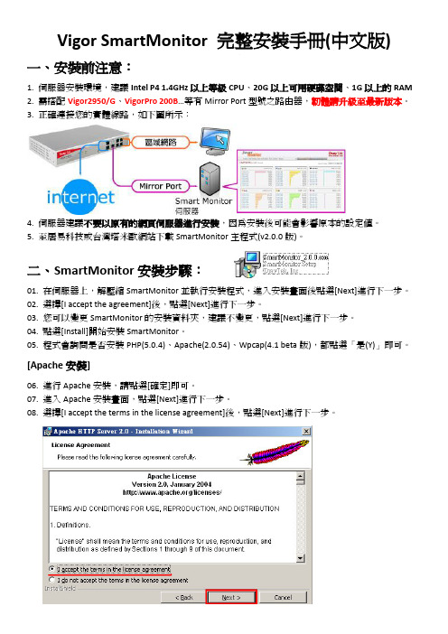
Vigor SmartMonitor 完整安裝手冊(中文版)一、安裝前注意:1. 伺服器安裝環境,建議Intel P4 1.4GHz以上等級CPU、20G以上可用硬碟空間、1G以上的RAM2. 需搭配Vigor2950/G、VigorPro 200B…等有Mirror Port型號之路由器,韌體請升級至最新版本。
3. 正確連接您的實體線路,如下圖所示:4. 伺服器建議不要以原有的網頁伺服器進行安裝,因為安裝後可能會影響原本的設定值。
5. 至居易科技或台灣塔米歐網站下載SmartMonitor主程式(v2.0.0版)。
二、SmartMonitor安裝步驟:01. 在伺服器上,解壓縮SmartMonitor並執行安裝程式,進入安裝畫面後點選[Next]進行下一步。
02. 選擇[I accept the agreement]後,點選[Next]進行下一步。
03. 您可以變更SmartMonitor的安裝資料夾,建議不變更,點選[Next]進行下一步。
04. 點選[Install]開始安裝SmartMonitor。
05. 程式會詢問是否安裝PHP(5.0.4)、Apache(2.0.54)、Wpcap(4.1 beta版),都點選「是(Y)」即可。
[Apache安裝]06. 進行Apache安裝,請點選[確定]即可。
07. 進入Apache安裝畫面,點選[Next]進行下一步。
08. 選擇[I accept the terms in the license agreement]後,點選[Next]進行下一步。
09. 閱讀Apache說明文件,點選[Next]進行下一步。
10. 請依下列說明進行設定:I. Network Domain: 請填入您的網域名稱,如:,若無網域可填入localhost。
II. Server Name: 請填入您的網址名稱,如:,若無網址可填入localhost。
III. Email Address: 請填入您的E-mail Address。
AVVIO RAPIDO Router mobili 5G 安装指南说明书
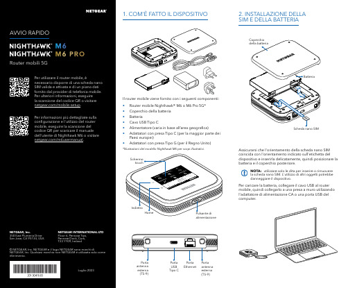
Per caricare la batteria, collegare il cavo USB al router mobile, quindi collegarlo a una presa a muro utilizzando l'adattatore di alimentazione CA o una porta USB del computer.Assicurarsi che l'orientamento della scheda nano SIM coincida con l'orientamento indicato sull'etichetta del dispositivo e inserirla delicatamente, quindi posizionare la batteria e il coperchio posteriore.NOTA: utilizzare solo le dita per inserire o rimuovere la scheda nano SIM. L'utilizzo di altri oggetti potrebbe danneggiare il dispositivo.1. COM'È FATTO IL DISPOSITIVO2. INSTALLAZIONE DELLA SIM E DELLA BATTERIAIl router mobile viene fornito con i seguenti componenti:• Router mobile Nighthawk® M6 o M6 Pro 5G*• Coperchio della batteria • Batteria• Cavo USB Tipo C• Alimentatore (varia in base all’area geografica)• Adattatori con presa Tipo C (per la maggior parte dei Paesi europei)•Adattatori con presa Tipo G (per il Regno Unito)*Illustrazioni del modello Nighthawk M6 per scopi illustrativi.antenna esterna (TS-9)antenna esterna (TS-9)USB Tipo CEthernetCONFORMITÀ NORMATIVA E NOTE LEGALIPer informazioni sulla conformità alle normative, compresala Dichiarazione di conformità UE, visitare il sito Web https:///it/about/regulatory/.Prima di collegare l'alimentazione, consultare il documento relativo alla conformità normativa.Può essere applicato solo ai dispositivi da 6 GHz: utilizzare il dispositivo solo in un ambiente al chiuso. L'utilizzo di dispositivi a 6 GHz è vietato su piattaforme petrolifere, automobili, treni, barche e aerei, tuttavia il suo utilizzo è consentito su aerei di grandi dimensioni quando volano sopra i 3000 metri di altezza. L'utilizzo di trasmettitori nella banda 5.925‑7.125 GHz è vietato per il controllo o le comunicazioni con sistemi aerei senza equipaggio.SUPPORTO E COMMUNITYDalla pagina del portale di amministrazione Web, fare clic sull'icona con i tre puntini nell'angolo in alto a destra per accedere ai file della guida e del supporto.Per ulteriori informazioni, visitare il sito netgear.it/support per accedere al manuale dell'utente completo e per scaricare gli aggiornamenti del firmware.È possibile trovare utili consigli anche nella Community NETGEAR, alla pagina /it.GESTIONE DELLE IMPOSTAZIONI TRAMITE L'APP NETGEAR MOBILEUtilizzare l'app NETGEAR Mobile per modificare il nome della rete Wi-Fi e la password. È possibile utilizzarla anche per riprodurre e condividere contenutimultimediali e accedere alle funzioni avanzate del router mobile.1. Accertarsi che il dispositivo mobile sia connesso a Internet.2. Eseguire la scansione del codice QR per scaricare l'appNETGEAR Mobile.Connessione con il nome e la password della rete Wi-Fi 1. Aprire il programma di gestione della rete Wi‑Fi deldispositivo.2. Individuare il nome della rete Wi‑Fi del router mobile(NTGR_XXXX) e stabilire una connessione.3. Only Connessione tramite EthernetPer prolungare la durata della batteria, l'opzione Ethernet è disattivata per impostazione predefinita. Per attivarla, toccare Power Manager (Risparmio energia) e passare a Performance Mode (Modalità performance).4. CONNESSIONE A INTERNETÈ possibile connettersi a Internet utilizzando il codice QR del router mobile da uno smartphone oppure selezionando manualmente il nome della rete Wi‑Fi del router e immettendo la password.Connessione tramite codice QR da uno smartphone 1. Toccare l'icona del codice QR sulla schermata inizialedello schermo LCD del router mobile.NOTA: quando è inattivo, lo schermo touch si oscura per risparmiare energia. Premere brevemente e rilasciare il pulsante di alimentazione per riattivare lo schermo.3. CONFIGURAZIONE DEL ROUTER MOBILETenere premuto il pulsante di accensione per due secondi, quindi seguire le istruzioni visualizzate sullo schermo per impostare un nome per la rete Wi‑Fi e una password univoci.La personalizzazione delle impostazioni Wi‑Fi consente di proteggere la rete Wi‑Fi del router mobile.Impostazioni APNIl router mobile legge i dati dalla scheda SIM e determina automaticamente le impostazioni APN (Access Point Name) corrette con i piani dati della maggior parte degli operatori. Tuttavia, se si utilizza un router mobile sbloccato con un operatore o un piano meno comune, potrebbe essere necessario immettere manualmente le impostazioni APN.Se viene visualizzata la schermata APN Setup Required (Configurazione APN richiesta), i dati APN dell’operatore non sono presenti nel nostro database ed è necessario inserirli manualmente. Immettere i valori fornitidall’operatore nei campi corrispondenti, quindi toccare Save (Salva) per completare la configurazione.NOTA: l’operatore determina le proprie informazioni APN e deve fornire le informazioni per il proprio piano dati. Si consiglia di contattare il proprio operatore per le impostazioni APN corrette e di utilizzare solo l’APN suggerito per il piano specifico.Schermata inizialeAl termine della configurazione, il router visualizza la schermata iniziale:Wi‑FiPotenza Carica Rete Codice QR connessione rapida Wi‑FiNome e Wi‑FiIcona del codice QR。
Vigor路由器设置
设置手册 >> VPN >> LAN到LAN(路由器到路由器)VPN设置参考IPSec(Main mode)--Vigor到Vigor一、VPN Server的建立:1.基本设置(Common Settings):a. 输入Profile Name.b. 选择 "Enable this Profile".c. 选择 Dial-In,Idle Timeout 选项设为0,这样可以始终维持IPSec隧道的开通直到远端拨入端发出终止命令。
3. 拨入设置(Dial-in Settings):a. 选择IPSec 模式。
b. 选中“Specify Remote VPN Gateway”。
c. 输入对方端VPN服务器IP(the Peer VPN Server IP)。
d. 输入IKE Pre-shared 值。
e. 选择一个IPSec 安全模式: 中等(AH)或高(ESP)。
4. TCP/IP网络设置(TCP/IP Network Settings):输入远端局域网内网IP地址及其网关。
二、VPN Client 的建立:1.基本设置(Common Settings):a. 输入Profile Name.b. 选择"Enable this Profile".c. 选择Dial-Out,Idle Timeout 选项设为0,这样可以始终维持IPSec隧道的开通直到远端发出终止命令。
如果选择Always on, 那只要连接一中断路由器就会自动重拨。
2. 拨出设置(Dial-Out Settings):a. 选择IPSec 模式。
b. 输入远端VPN server的IP地址/主机名字。
c. 输入IKE Pre-shared 值。
d. 选择一个IPSec 安全模式: 中等(AH)或高(ESP)。
4. TCP/IP网络设置(TCP/IP Network Settings):输入远端局域网内网IP地址及其网关。
Avvio rapido Router mobile 5G M5 用户手册说明书
3. Inserire il coperchio posteriore. Labatteria viene fornita parzialmente carica. Per caricarla completamente, collegare il cavo USB al router mobile, quindi collegarlo al laptop o all'adattatore di alimentazione CA a ricarica rapida fornito.Configurazione del router mobile1. Tenere premuto il pulsante dialimentazione per due secondi.Per proteggere meglio la rete, al primo accesso al router mobile, viene richiesto di configurare le credenziali di accesso.2. Per personalizzare le impostazioni delrouter mobile, seguire le istruzioni visualizzate sullo schermo.Installare la scheda SIM e la batteriaIl router mobile richiede una scheda SIM per connettersi alla rete del provider di telefonia mobile. Per ottenere una scheda SIM valida, contattare il proprio provider di telefoniamobile. Per sapere come contattare i provider di telefonia mobile e per le informazioni che potrebbe essere necessario fornire loro, utilizzare il codice QR o visitare il sito https:///mobile-setup .Non utilizzare strumenti, penne o graffette per inserire o rimuovere la scheda SIM, poiché il router mobile potrebbe danneggiarsi e non essere1. 2.Introduzione al router mobileUSB CConnettore antenna esterna TS-9Contenuto della confezione• Router mobile Nighhawk M5 5G • Coperchio delle batterie • Batteria• Cavo USB Tipo C• Adattatore di alimentazione CA a ricarica rapida•Guida introduttivaIndicatore di reteSchermata inizialeNella schermata iniziale vengono visualizzati il nome e la password della rete Wi-Fi del router mobile. L'indicatore di rete indica la rete wireless alla quale si è connessi.NETGEAR, Inc.350 East Plumeria Drive San Jose, CA 95134, USAMaggio 2022NETGEAR INTERNATIONAL LTD Floor 1, Building 3,University Technology Centre Curraheen Road, Cork, T12EF21, Irlanda © NETGEAR, Inc. NETGEAR e il logo NETGEAR sonomarchi di NETGEAR, Inc. Qualsiasi marchio non-NETGEAR è utilizzato solo come riferimento.Nota: l'aspetto della schermata iniziale dipende dal modello.EthernetAndare su /support per trovare le risposte alle domande e accedere agli ultimi download.È possibile trovare utili consigli anche nella Community NETGEAR, alla pagina.Per un'esperienza ottimale, si consiglia di utilizzare solo la batteria NETGEAR, il cavo USB di tipo C el'adattatore di alimentazione CA forniti in dotazione con il router mobile.Conformità normativa e note legaliPer informazioni sulla conformità alle normative, inclusa la Dichiarazione di conformità UE, visitare il sito Webhttps:///about/regulatory/ per accedere al manuale utente completo e per scaricare gli aggiornamenti del firmware.Prima di collegare l'alimentazione, consultare il documento relativo alla conformità normativa.Supporto e CommunityGestione del Wi-Fi tramite LCDÈ possibile gestire la rete Wi-Fi e modificare le impostazioni Wi-Fi dallo schermo LCD.Modifica del nome di rete e della password Wi-Fi 1. Nella pagina iniziale, toccare l'icona WiFi.2. Toccare WiFi, quindi scegliere tra le reti Wi-Fidisponibili.3. Toccare WiFi Name (Nome Wi-Fi) e inserire lemodifiche.4. Toccare WiFi Password (Password Wi-Fi) einserire le modifiche.Programma di gestione Wi-FiÈ possibile utilizzare un browser per visualizzare e modificare le impostazioni del router mobile.Accedi1. Sul router mobile, accedere alla schermata LCDSettings (Impostazioni LCD), quindi toccarel'icona More (Altro). Toccare Device Information (Informazioni sul dispositivo) e cercare l'URL delprogramma di gestione Wi-Fi.2. Sul dispositivo Wi-Fi connesso al router mobile,digitare l'URL del programma di gestione Wi-Finella barra del browser.3. Effettuare l'accesso come amministratore. Lecredenziali di accesso predefinite sono stampatesull'etichetta del prodotto. Impostazioni LCDVisualizzazione o modifica delle impostazioni Nella home page, toccare l'icona Settings (Impostazioni).Modifica della banda Wi-Fi1. Nella pagina iniziale, toccare l'icona WiFi.2. Toccare Band (Banda).3. Selezionare la banda Wi-Fi a 2,4 GHz, 5 GHz odual.Connettersi a InternetNota: nella schermata iniziale del router mobilevengono visualizzati il nome e la password dellarete Wi-Fi. Lo schermo diventa scuro per entrare inmodalità di risparmio energetico. Premere e rilasciareil pulsante di alimentazione per riattivare lo schermo.Sul laptop o su un altro dispositivo Wi-Fi1. Aprire il programma di gestione delleconnessioni di rete Wi-Fi.2. Individuare il nome della rete Wi-Fi del routermobile (NTGR-XXXX) e stabilire una connessione.3. Immettere la password Wi-Fi del router mobile.4. Avviare il browser Internet.Nota: la batteria e il router mobile potrebberoriscaldarsi durante il funzionamento. Si tratta diun evento normale. Se si utilizza il dispositivocome router wireless fisso, rimuovere la batteriae alimentare il router utilizzando l'adattatore dialimentazione CA a ricarica rapida fornito. In tal modola durata della batteria viene prolungata e si riduce ilriscaldamento.Utilizzare SOLO l'adattatore di alimentazione CA aricarica rapida fornito per utilizzare il router mobilesenza batteria.Scaricare l'app NETGEAR MobileUtilizzare l'app NETGEAR Mobile permodificare il nome della rete Wi-Fie la password. È possibile utilizzarlaanche per riprodurre e condividerecontenuti multimediali e abilitare lafunzione Travel Router.1. Collegare il dispositivo mobile a Internet.2. Per scaricare l'app NETGEAR Mobile, utilizzare ilcodice QR. Il collegamento consente di accedereall'app nell'Apple Store o in Google Play Store, aseconda del dispositivo mobile.。
Vigor 2xxx系列路由器中文使用手册
Vigor 全系列中文说明书(版本1)第一章基本设置 (Basic Setup)1.管理员密码设置(Administrator Password Setup)--------------------------------------22. 配置局域网IP和DHCP(Lan TCP/IP and DHCP Setup)-----------------------------2 第二章快速设置 (Quick Setup)1.互联网访问设置(Internet Access Setup)--------------------------------------------------5 第三章高级设置 (Advanced Setup)1.动态域名设置(Dynamic DDNS Setup)----------------------------------------------------11 2.拨号时间表设置(Call Schedule Setup)----------------------------------------------------13 3.NAT(网络地址翻译)设置(NAT Setup)----------------------------------------------------16 4.静态路由设置(Static Route Setup)---------------------------------------------------------22 5.IP过虑和防火墙设置(IP Filter/Firewall Setup)----------------------------------------25 6.VPN和远程访问设置(VPN and Remote Access Setup)-------------------------------31 7.UPnP服务设置(UpnP Service Setup)-----------------------------------------------------47 8.VoIP设置(VoIP Setup)-----------------------------------------------------------------------48 9.VLAN和流量控制(VLAN/Rate Control)------------------------------------------------5310.QoS控制设置(QoS Control Setup)--------------------------------------------------------54 第四章系统管理(System Management)1.在线状态(Online Status)-----------------------------------------------------------------------592.VPN连接状态(VPN Connection Management)------------------------------------------593.配置备份与导入(Configuration Backup/Restoration)----------------------------------604.系统日志与邮件警报(Syslog/Mail Alert Setup)------------------------------------------615.时间设置(Time Setup)-------------------------------------------------------------------------626.管理设置(Management Setup)---------------------------------------------------------------627.诊断工具(Diagnostic Tools)-------------------------------------------------------------------638.重启系统(Reboot System)---------------------------------------------------------------------679.软件版本升级(Firmware Upgrade)---------------------------------------------------------68第一章基本设置(Basic Setup)功能介绍:在基本设置组中,你能改变管理员密码和内网(LAN)接口的IP配置,以及本地DHCP 服务器设置1.管理员密码设置(Administrator Password Setup)因为安全性的原因,我们强烈建议你为路由器设置一个管理员密码。
DrayTek Vigor927双广域网安全路由器快速入门指南(适用于有线型号)说明书
Vigor2927Dual-WAN Security Router Quick Start Guide(for Wired Model)Version: 1.6Firmware Version: V4.4.2(For future update, please visit DrayTek web site)Date: November 23, 2022Intellectual Property Rights (IPR) InformationCopyrights © All rights reserved. This publication contains information that is protected by copyright. No part may be reproduced, transmitted, transcribed, stored ina retrieval system, or translated into any language without writtenpermission from the copyright holders.Trademarks The following trademarks are used in this document:●Microsoft is a registered trademark of Microsoft Corp.●Windows, 8, 10, 11 and Explorer are trademarks of Microsoft Corp.●Apple and Mac OS are registered trademarks of Apple Inc.●Other products may be trademarks or registered trademarks of theirrespective manufacturers.Safety Instructions and ApprovalSafety Instructions ●Read the installation guide thoroughly before you set up the router.●The router is a complicated electronic unit that may be repaired only beauthorized and qualified personnel. Do not try to open or repair therouter yourself.●Do not place the router in a damp or humid place, e.g. a bathroom.●Do not stack the routers.●The router should be used in a sheltered area, within a temperaturerange of +5 to +40 Celsius.●Do not expose the router to direct sunlight or other heat sources. Thehousing and electronic components may be damaged by direct sunlight or heat sources.●Do not deploy the cable for LAN connection outdoor to preventelectronic shock hazards.●Keep the package out of reach of children.●When you want to dispose of the router, please follow local regulationson conservation of the environment.Warranty We warrant to the original end user (purchaser) that the router will be free from any defects in workmanship or materials for a period of two (2) yearsfrom the date of purchase from the dealer. Please keep your purchasereceipt in a safe place as it serves as proof of date of purchase. During thewarranty period, and upon proof of purchase, should the product haveindications of failure due to faulty workmanship and/or materials, we will, atour discretion, repair or replace the defective products or components,without charge for either parts or labor, to whatever extent we deemnecessary tore-store the product to proper operating condition. Anyreplacement will consist of a new or re-manufactured functionallyequivalent product of equal value, and will be offered solely at ourdiscretion. This warranty will not apply if the product is modified, misused,tampered with, damaged by an act of God, or subjected to abnormal workingconditions. The warranty does not cover the bundled or licensed software ofother vendors. Defects which do not significantly affect the usability of theproduct will not be covered by the warranty. We reserve the right to revisethe manual and online documentation and to make changes from time totime in the contents hereof without obligation to notify any person of suchrevision or changes.EU Declaration of ConformityWe DrayTek Corp. , office at No.26, Fushing Rd., Hukou, Hsinchu Industrial Park, Hsinchu 303, Taiwan, declare under our soleresponsibility that the product●Product name: Dual-WAN Security Router●Model number: Vigor2927●Manufacturer: DrayTek Corp.●Address: No.26, Fushing Rd., Hukou, Hsinchu Industrial Park,Hsinchu 303, Taiwan.is in conformity with the relevant Union harmonisation legislation:EMC Directive 2014/30/EU , Low Voltage Directive 2014/35/EU, ErP 2009/125/EC and RoHS 2011/65/EU with reference to thefollowing standardsStandard Version / Issue dateEN 550322015+AC:2016 class BEN 61000-3-22014 Class AEN 61000-3-32013EN 550242010+A1:2015EN 62368-12014+A11:2017EN IEC 63000:2018 2018EC No. 1275/2008 2008Hsinchu2nd January, 2020Calvin Ma / President .Signature)(Legal (place) (date)Declaration of ConformityWe DrayTek Corp. , office at No.26, Fushing Rd., Hukou, Hsinchu Industrial Park, Hsinchu 303, Taiwan, declare under our soleresponsibility that the product●Product name: Dual-WAN Security Router●Model number: Vigor2927●Manufacturer: DrayTek Corp.●Address: No.26, Fushing Rd., Hukou, Hsinchu Industrial Park, Hsinchu 303, Taiwan●Importer: CMS Distribution Ltd: Bohola Road, Kiltimagh, Co Mayo, Irelandis in conformity with the relevant UK Statutory Instruments:The Electromagnetic Compatibility Regulations 2016 (SI 2016 No.1091), The Electrical Equipment (Safety) Regulations 2016 (SI2016 No.1101), The Ecodesign for Energy-Related Products and Energy Information (Amendment) (EU Exit) Regulations 2019 (SI2019 No.539) and The Restriction of the Use of Certain Hazardous Substances in Electrical and Electronic Equipment Regulations2012 (SI 2012 No. 3032) with reference to the following standards:Standard Version / Issue dateEN 550322015+AC:2016 class BEN 61000-3-22014 Class AEN 61000-3-32013EN 550242010+A1:2015EN 62368-12014+A11:2017EN IEC 63000:2018 2018EC No. 1275/2008 2008Hsinchu2nd January, 2020Calvin Ma / President .Signature)(Legal (place) (date)Regulatory InformationFederal Communication Commission Interference StatementThis equipment has been tested and found to comply with the limits for a Class B digital device, pursuant to Part 15 of the FCC Rules. These limits are designed to provide reasonable protection against harmful interference in a residential installation. This equipment generates, uses and can radiate radio frequency energy and, if notinstalled and used in accordance with the instructions, may cause harmful interference to radio communications. However, there is no guarantee that interference will not occur in a particular installation. If this equipment does cause harmful interference to radio or television reception, which can be determined by turning the equipment off and on, the user is encouraged to try to correct the interference by one of the following measures:● Reorient or relocate the receiving antenna.● Increase the separation between the equipment and receiver.● Connect the equipment into an outlet on a circuit different from that to which the receiver is connected.●Consult the dealer or an experienced radio/TV technician for help.This device complies with Part 15 of the FCC Rules. Operation is subject to the following two conditions: (1) This device may not cause harmful interference, and(2) This device may accept any interference received, including interference that may cause undesired operation.Company nameABP International Inc.Address 13988 Diplomat Drive Suite 180 Dallas TX 75234 ZIP Code 75234E-mail *******************USA Local RepresentativeContact PersonMr. Robert MesserTel.19728311600Caution:Any changes or modifications not expressly approved by the party responsible for compliance could void the user's authority to operate this equipment.*The external power supply used for each product will be model dependent.1 2 3 4 5 6 7 8 9 A Manufacturer CWT CWT CWT CWT CWT APD APD APD APD BAddressNo. 222, Sec. 2, Nankan Rd.,Lujhu Township, Taoyuan County 338, Taiwan No. 222, Sec. 2, Nankan Rd.,Lujhu Township, Taoyuan County 338, Taiwan No. 222, Sec. 2, Nankan Rd.,Lujhu Township, Taoyuan County 338, Taiwan No. 222, Sec. 2, Nankan Rd.,Lujhu Township, Taoyuan County 338, Taiwan No. 222, Sec. 2, Nankan Rd.,Lujhu Township, Taoyuan County 338, TaiwanNo.5, Lane 83, Lung-Sou St., Taoyuan City 330, Taiwan No.5, Lane 83, Lung-Sou St., Taoyuan City 330, Taiwan No.5, Lane 83, Lung-Sou St., Taoyuan City 330, Taiwan No.5, Lane 83,Lung-Sou St., Taoyuan City 330, Taiwan2ABB012F UK 2ABB018F UK 2ABL024F UK 2ABL030F UK 2ABN036F UK WA-12M12FG WB-18D12FG WA-24Q12FG WA-36A12FG C Model identifier 2ABB012F EU 2ABB018F EU 2ABL024F EU 2ABL030F EU 2ABN036F EU WA-12M12FK WB-18D12FK WA-24Q12FK WA-36A12FK D Input voltage 100~240V 100~240V 100~240V 100~240V 100~240V 100~240V 100~240V 100~240V 100~240VInput AC frequency 50/60Hz 50/60Hz 50/60Hz 50/60Hz 50/60Hz 50/60Hz 50/60Hz 50/60Hz 50/60Hz EOutput voltage DC 12.0V 12.0V 12.0V 12.0V 12.0V 12.0V 12.0V 12.0V 12.0VF Output current 1.0A1.5A2.0A2.5A3.0A 1.0A 1.5A 2.0A 3.0AG Output power 12.0W 18.0W 24.0W 30.0W 36.0W 12.0W 18.0W 24.0W 36.0W H Average activeefficiency 84.9% 86.2% 87.6% 87.8% 89.8% 83.7% 85.4% 88.6% 88.2% IEfficiency at low load 10%73.6% 78.0% 81.3% 83.3% 83.7% 74.5% 80.5% 86.4% 85.4% J No-load powerconsumption0.07W 0.07W 0.07W 0.07W 0.07W 0.07W 0.10W 0.07W 0.10WExternal power supply (Power Adapter) information. For more update, please visit .T a b l e o f C o n t e n t s1. Package Content (1)2. Panel Explanation (2)2.1 Vigor2927 (2)3. Hardware Installation (4)3.1 Network Connection (4)3.2 Wall-Mounted Installation (5)4. Software Configuration (6)5. Customer Service (13)Be a Registered Owner (13)Firmware & Tools Updates (13)1. P a c k a g e C o n t e n tTake a look at the package content. If there is anything missed or damaged, please contact DrayTek or dealer immediately. Besides, the content is subject to the real package.Vigor RouterQuick Start GuideRJ-45 Cable (Ethernet)The type of the power adapter depends on the country that the router will be installed. * The maximum power consumption is 22 Watt .UK-type Power AdapterEU-type Power AdapterUSA/Taiwan-type Power AdapterAU/NZ-type Power Adapter2. P a n e l E x p l a n a t i o n2.1 V i g o r 2927No. LEDStatusExplanationOff The router is powered off.ACT Blinking The router is powered on and running normally.On Internet connection is ready. OffInternet connection is not ready. WAN2/WAN1 Blinking The data is transmitting.On USB device is connected and ready for use. OffNo USB device is connected. USB1/USB2 Blinking The data is transmitting. On The DMZ function is enabled. OffThe DMZ function is disabled. DMZ Blinking The data is transmitting.On The QoS function is active. QoS Off The QoS function is inactive. On The VPN tunnel is active. Off VPN services are disabledVPNBlinking Traffic is passing through VPN tunnel. On The Web Content Filter is active. (It is enabled from Firewall >> General Setup ). (1)WCFOffWCF is disabled.WAN1,WAN2 / P6 On The port is connected. OffThe port is disconnected. Left LED Blinking The data is transmitting.On The port is connected with 1000Mbps. Right LED OffThe port is connected with 10/100Mbps. LAN P1-P5 On The port is connected. OffThe port is disconnected. Left LED Blinking The data is transmitting.On The port is connected with 1000Mbps. (2)Right LEDOff The port is connected with 10/100MbpsNo.Interface Description(3) FactoryResetRestore the default settings. Usage: Turn on the router(ACT LED is blinking). Press the hole and keep for more than5 seconds. When you see the ACT LED begins to blink rapidlythan usual, release the button. Then the router will restartwith the factory default configuration.(4) USB Connecter for a USB device (for 3G/4G USB Modem or printer or thermometer).WAN1 Connecter for local network devices or modem for accessing Internet.WAN2 / P6 Connecter for local network devices or modem for accessing Internet.It is a switchable port. It can be used for LAN connection or WAN connection according to the settings configured in WUI.(5)LAN P1-P5 Connecters for local network devices.PWR Connecter for a power adapter. (6)ON/OFF PowerSwitch.3.H a r d w a r e I n s t a l l a t i o nThis section will guide you to install the router through hardware connection and configure the router’s settings through web browser.Before starting to configure the router, you have to connect your devicescorrectly.3.1N e t w o r k C o n n e c t i o n1.Connect the cable Modem/DSL Modem/Media Converter to any WAN port ofrouter with Ethernet cable (RJ-45).2.Connect one end of an Ethernet cable (RJ-45) to one of the LAN ports of therouter and the other end of the cable (RJ-45) into the Ethernet port on yourcomputer.3.Connect one end of the power adapter to the router’s power port on therear panel, and the other side into a wall outlet.4.Power on the device by pressing down the power switch on the rear panel.5.The system starts to initiate. After completing the system test, the ACT LEDwill light up and start blinking. (For the detailed information of LED status,please refer to section 2. Panel Explanation)3.2 W a l l -M o u n t e d I n s t a l l a t i o nVigor router has keyhole type mounting slots on the underside.1. Drill two holes on the wall. The distance between the holes shall be 168mm.2.Fit screws into the wall using the appropriate type of wall plug.Note The recommended drill diameter shall be 6.5mm (1/4”).3. When you finished about procedure, the router has been mounted on thewall firmly.4. S o f t w a r e C o n f i g u r a t i o nTo access Internet, please finish basic configuration after completing the hardware installation.The Quick Start Wizard is designed for you to easily set up your router for Internet access. You can directly access the Quick Start Wizard via Web User Interface. Make sure your PC connects to the router correctly.NoteYou may either simply set up your computer to get IP dynamically from the router or set up the IP address of the computer to be the same subnet as the default IP address of Vigor router192.168.1.1. For the detailed information, please refer to - Trouble Shooting of the user’s guide.Open a web browser on your PC and type http://192.168.1.1. A pop-up window will open to ask for username and password. Please enter “admin/admin” as the Username/Password and click Login.NoteIf you fail to access to the web configuration, please go to “Trouble Shooting” on User’s Guide for detecting and solving your problem.Now, the Main Screen will pop up. Click Wizards>>Quick Start Wizard.NoteThe home page will change slightly in accordance with the router you have.If your router can be under an environment with high speed NAT, theconfiguration provide here can help you to deploy and use the router quickly. The first screen of Quick Start Wizard is entering login password. After typing the password, please click Next .On the next page as shown below, please select the WAN interface that you use. If Ethernet interface is used, please choose WAN1 or WAN2; if wireless 2.4G/5G connection is used, please choose WAN3 or WAN4; if 3G USB modem is used, please choose WAN5 or WAN6. Then click Next for next step. Each WAN interface will bring up specific configuration page.Click Next. You have to select the appropriate Internet access type (PPPoE, PPTP, L2TP, Static IP or DHCP) according to the information from your ISP.Here we take PPPoE and DHCP modes for WAN connection as examples.F o r P P P o E C o n n e c t i o n1.Choose WAN1 as WAN Interface and click the Next button; you will get thefollowing page.2.Select PPPoE and click Next to get the following page.3.Enter the Username/Password provided by your ISP. Then click Next forviewing the summary of such connection.4.Click Finish. A page of Quick Start Wizard Setup OK will appear.Then,the system status of this protocol will be shown.5.Now, you can enjoy surfing on the Internet.F o r D H C P C o n n e c t i o n1.Choose WAN1 as WAN Interface and click the Next button; you will get thefollowing page.2.Select DHCP and click Next to get the following page.3.Enter the hostname and / or MAC address provided by your ISP. Then clickNext for viewing summary of such connection.4.Click Finish. A page of Quick Start Wizard Setup OK will appear.Then,the system status of this protocol will be shown.5.Now, you can enjoy surfing on the Internet.5.C u s t o m e r S e r v i c eIf the router cannot work correctly after trying many efforts, please contact your dealer for further help right away. For any questions, please feel free to send ***************************.B e a R e g i s t e r e d O w n e rWeb registration is preferred. You can register your Vigor router viahttps://.F i r m w a r e&T o o l s U p d a t e sDue to the continuous evolution of DrayTek technology, all routers will beregularly upgraded. Please consult the DrayTek web site for more information on newest firmware, tools and documents.https://。
- 1、下载文档前请自行甄别文档内容的完整性,平台不提供额外的编辑、内容补充、找答案等附加服务。
- 2、"仅部分预览"的文档,不可在线预览部分如存在完整性等问题,可反馈申请退款(可完整预览的文档不适用该条件!)。
- 3、如文档侵犯您的权益,请联系客服反馈,我们会尽快为您处理(人工客服工作时间:9:00-18:30)。
Vigor 全系列中文说明书(版本1)第一章基本设置(Basic Setup)1.管理员密码设置(Administrator Password Setup)--------------------------------------22. 配置局域网IP和DHCP(Lan TCP/IP and DHCP Setup)-----------------------------2 第二章快速设置(Quick Setup)1.互联网访问设置(Internet Access Setup)--------------------------------------------------5 第三章高级设置(Advanced Setup)1.动态域名设置(Dynamic DDNS Setup)----------------------------------------------------11 2.拨号时间表设置(Call Schedule Setup)----------------------------------------------------13 3.NAT(网络地址翻译)设置(NAT Setup)----------------------------------------------------16 4.静态路由设置(Static Route Setup)---------------------------------------------------------22 5.IP过虑和防火墙设置(IP Filter/Firewall Setup)----------------------------------------25 6.VPN和远程访问设置(VPN and Remote Access Setup)-------------------------------31 7.UPnP服务设置(UpnP Service Setup)-----------------------------------------------------47 8.VoIP设置(VoIP Setup)-----------------------------------------------------------------------48 9.VLAN和流量控制(VLAN/Rate Control)------------------------------------------------5310.QoS控制设置(QoS Control Setup)--------------------------------------------------------54 第四章系统管理(System Management)1.在线状态(Online Status)-----------------------------------------------------------------------592.VPN连接状态(VPN Connection Management)------------------------------------------593.配置备份与导入(Configuration Backup/Restoration)----------------------------------604.系统日志与邮件警报(Syslog/Mail Alert Setup)------------------------------------------615.时间设置(Time Setup)-------------------------------------------------------------------------626.管理设置(Management Setup)---------------------------------------------------------------627.诊断工具(Diagnostic T ools)-------------------------------------------------------------------638.重启系统(Reboot System)---------------------------------------------------------------------679.软件版本升级(Firmware Upgrade)---------------------------------------------------------68第一章基本设置(Basic Setup)功能介绍:在基本设置组中,你能改变管理员密码和内网(LAN)接口的IP配置,以及本地DHCP 服务器设置1.管理员密码设置(Administrator Password Setup)因为安全性的原因,我们强烈建议你为路由器设置一个管理员密码。
路由器初始是没有密码的。
如果你不设置密码,任何用户都能从本地网络或者Internet登陆到路由器并改变配置。
单击Administrator Password Setup,打开如下所以的屏幕。
Old Password(原始密码):输入当前的管理员密码。
如果是第一次设置密码,该行为空。
New Password(新密码):属于一个新的管理员密码。
Retype New Password(确认新密码):再次输入新的密码进行确认。
单击OK。
2.配置局域网IP和DHCP(Lan TCP/IP and DHCP Setup)对于LAN接口,有两个IP地址设置组合。
1st IP address/netmask是为私网用户或NA T 用户使用,2nd IP address/netmask是为具有公网地址的用户使用。
为了使用公网地址,你应该向你的ISP申请一个公网IP段。
例如,ISP会给某些DSL帐户分配少许公网IP地址给你的本地网络使用。
你能给你的路由器使用一个IP,2nd IP address/netmask应该配置为公网IP。
其他的本地PC应该设置路由器的IP作为默认网关。
当DSL建立到ISP的连接后,每个本地PC将直接路由到Internet。
同时你可以使用1st IP address/netmask连接其他的私网用户。
这些用户的IP地址将被路由器转换为2nd IP地址并通过DSL连接发送出去。
For NA T Usage:(默认:总是启用)1st IP Address:连接到本地私网的私有IP地址(默认:192.168.1.1)。
1st Subnet Mask:本地私网的子网掩码(默认:255.255.255.0/24)。
For IP Routing Usage:(默认:不启用)Enable:启用第二个IP地址设置。
Disable:不启用第二个IP地址设置。
2nd IP Address:设置一个公网IP地址。
2nd Subnet Mask:公网地址的子网掩码。
RIP Protocol Control:Disable:屏蔽LAN接口上的RIP包交换。
1st Subnet:设置第一个子网与连接到LAN接口的相邻路由器交换RIP数据包。
2nd Subnet:设置第二个子网与连接到LAN接口的相邻路由器交换RIP数据包。
配置DHCP服务器DHCP(动态主机配置协议)。
为任何配置为DHCP客户端的本地用户分派相关的IP设置Activate:(默认:yes)。
Y es:启用DHCP服务器。
No:不启用DHCP服务器。
Start IP Address:设置IP地址池的起始IP地址。
IP Pool Counts:设置IP地址池中的IP数量。
Gateway IP Address:为DHCP服务器设置网关IP地址。
通常,当路由器作为默认网关时,这个地址应该与LAN口的第一个IP地址相同。
DNS Server IP Address:(默认:没有)。
DNS(域名系统)。
每个Internet主机必须有一个唯一的IP地址,他们也可以有一个人类所熟悉的容易记忆的名字,如:。
DSN服务器的功能是翻译这个名字到他的等价的IP地址。
Primary IP Address:设置第一个DNS服务器的IP地址。
Secondary IP Address:设置第二个DNS服务器的IP地址。
注释:如果第一和第二个DNS服务器IP地址都没有设置,路由器在向本地用户分配IP地址时使用路由器自己的IP地址作为客户的DNS代理服务器,并维护一个DNS缓存。
如果域名对应的IP地址已经在DNS缓存中,路由器立即解析这个域名。
否则,路由器转发DNS 查询包到外部DNS服务器。
第二章快速设置1.互联网访问设置(Internet Access Setup)功能介绍:在快速设置组中,你能配置路由器使用不同的方式访问Internet(如:PPPoE、PPTP或动态/静态IP)。
对于大多数用户来说,Internet访问是最主要的应用。
本路由器支持通过以太网的广域网(WAN)接口访问Internet。
下面的部分将详细说明不同的宽带访问设置。
当你从快速设置组中点击Internet Access Setup时,出现如下设置页。
有三种可用的方法访问Internet。
PPPoE:大多数DSL modem用户使用的方法。
所有本地用户能共享一个PPPoE连接访问Internet。
PPTP:某些DSL服务供应商提供一个特殊的DSL modem(如:阿尔卡特的DSL modem)。
这种类型的modem仅支持使用PPTP隧道的方法去访问Internet。
在这些方法中,你创建一个PPTP隧道来承载PPP会话并在DSL modem处终止。
一旦隧道建立,这种类型的DSL modem将转发PPP会话到ISP。
当PPP会话建立时,所有的本地用户将能共享这个PPP会话去访问Internet。
Static or Dynamic IP:在这个页面你可以配置W AN口使用静态(固定)IP或者动态(DHCP客户端)IP地址。
大多数的Cable用户将使用动态IP地址的方式从Cable头端系统获取公网地址。
在你连接一个宽带访问设备(如:DSL/Cable modem)到路由器之前,你需要知道你的ISP提供的是哪种类型的Internet访问方式。
一下部分涉及到广泛使用的四种宽带访问服务。
他们是PPPoE客户端、PPTP客户端、DSL使用静态IP、Cable使用的动态IP(DHCP客户端)。
大多数情况,你将从宽带访问服务提供商处得到DSL或Cable modem。