常见齿轮失效形式
闭式软齿轮传动的主要失效形式
闭式软齿轮传动的主要失效形式闭式软齿轮传动是一种常见的传动形式,它具有结构简单、传动平稳等优点,被广泛应用于各种机械设备中。
然而,在使用闭式软齿轮传动时,由于各种因素的影响,可能会导致其失效。
下面将从多个方面介绍闭式软齿轮传动的主要失效形式。
1. 磨损失效磨损是闭式软齿轮传动中最常见的失效形式之一。
磨损通常是由于接触面间的摩擦引起的,这会导致齿轮表面逐渐磨损、变形或变薄,并最终导致齿轮无法正常工作。
此外,在润滑不良或使用寿命过长的情况下,磨损也会加剧。
2. 疲劳失效疲劳是另一种常见的闭式软齿轮传动失效形式。
当齿轮在长时间内重复受到载荷作用时,其材料可能会发生微裂纹,并逐渐扩大到致命尺寸。
这样就会导致齿轮出现裂纹、断裂或变形等问题,从而影响传动效果。
3. 腐蚀失效腐蚀是闭式软齿轮传动中较为罕见的失效形式,但在一些特定情况下可能会发生。
例如,在潮湿或酸性环境中使用时,齿轮表面可能会被腐蚀,导致其表面粗糙度增加、失去光泽甚至产生裂纹。
此外,在某些化学介质中使用时,也可能会导致闭式软齿轮传动的腐蚀失效。
4. 偏心失效偏心是指闭式软齿轮传动中的轴心不在同一条直线上。
偏心通常由于安装不当或机械故障引起。
如果偏心严重,就会导致齿轮与齿轮之间的配合不良,从而影响传动效果。
5. 温度失效温度也是闭式软齿轮传动中一个重要的因素。
如果在高温环境下使用闭式软齿轮传动,则可能会出现变形、损坏或松动等问题。
此外,在低温环境下使用时,润滑油可能会变得黏稠或凝固,从而影响传动效果。
6. 齿轮间隙失效齿轮间隙是指闭式软齿轮传动中齿轮与齿轮之间的距离。
如果齿轮间隙过大或过小,则会导致闭式软齿轮传动的失效。
例如,如果齿轮间隙过大,则会导致传动不稳定或噪声过大;如果齿轮间隙过小,则会导致磨损加剧或卡死等问题。
总之,闭式软齿轮传动的失效形式有很多种。
为了保证其正常工作,我们需要注意以下几点:正确安装和维护闭式软齿轮传动、选择适当的润滑油和润滑方法、避免超载和过温等情况,并在发现任何异常时及时进行检查和维修。
简述齿轮常见的失效形式及特点
齿轮失效形式及特点
齿轮作为机械传动装置中常见的零件,其失效形式多种多样。
下面将介绍几种常见的齿轮失效形式及其特点。
1. 磨损失效
磨损是最常见的齿轮失效形式之一,主要是由于齿轮表面的摩擦和磨损引起的。
具体表现为齿面磨损、齿面点蚀、齿面斑点磨损等。
磨损失效主要由于润滑不良、负载过大、工作环境恶劣等原因引起。
2. 齿面断裂
齿面断裂是指齿轮齿面出现裂纹或齿面完全断裂。
齿面断裂多发生在齿根处,其特点是断口光滑,常伴有齿面疲劳痕迹。
齿面断裂主要是由于齿轮过载、材料强度不足、制造缺陷等原因引起。
3. 齿根断裂
齿根断裂是指齿轮齿根处发生断裂,断口呈现韧性断口。
齿根断裂多发生在负荷集中区域,其特点是断口不平整,常伴有齿根疲劳痕迹。
齿根断裂主要是由于齿轮过载、应力集中、材料强度不足等原因引起。
4. 腐蚀失效
腐蚀失效是指齿轮表面受到化学物质侵蚀而产生的失效。
腐蚀失效的特点是齿面出现腐蚀斑点、齿面粗糙等。
腐蚀失效主要是由于工作环境中存在腐蚀介质、润滑不良等原因引起。
以上是齿轮常见的失效形式及其特点。
在实际应用中,为了避免齿轮失效,可以采取以下措施:选择合适的润滑剂,保持良好的润滑
状态;合理设计齿轮结构,提高齿轮的强度及工作寿命;加强齿轮的维护保养,定期检查齿轮状态并及时更换磨损严重的齿轮。
通过这些措施的实施,可以有效预防齿轮的失效,延长齿轮的使用寿命。
总结:了解齿轮常见的失效形式及其特点对于提高齿轮传动的可靠性和寿命具有重要意义。
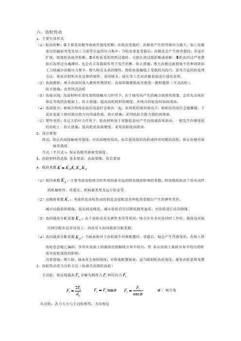
齿轮传动的失效分析)
一般来说,齿轮传动的失效主要发生在轮齿上。
轮齿部分的失效形式分为两大类:轮齿折断,齿面失效。
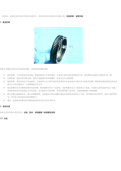
1. 轮齿折断折断失效通常有轮齿的弯曲疲劳折断、过载折断和随机折断。
•疲劳折断:工作时轮齿反复受载,使得齿根处产生疲劳裂纹,并逐步扩展以至轮齿折断的失效。
疲劳裂纹多起源于齿根受拉的一侧。
•过载折断:齿轮受到突然过载,或经严重磨损后齿厚减薄时,轮齿会发生过载折断。
•随机折断:通常是指由于轮齿缺陷、点蚀或其它应力集中源在轮齿某部位形成过高应力集中而引起轮齿折断。
断裂部位随缺陷或过高有害残余应力的位置而定,与齿根圆角半径无关。
•轮齿折断的形式有整体折断和局部折断。
整体折断多发生于直齿轮,局部折断多发生于斜齿和人字齿轮,齿宽较大的直齿轮和由于安装、制造因素使得局部受载过大的直齿轮,也可能发生局部折断。
疲劳折断的断口较光滑,过载折断的断口则较粗糙。
•增大齿根过渡圆角半径,减小齿面粗糙度,对齿根进行喷丸或碾压强化处理消除该处的加工刀痕,选用韧性较好的材料,采用合理的变位等,均有助于提高轮齿的抗折断能力。
•通常,轮齿疲劳折断是闭式硬齿面齿轮传动的主要失效形式。
2. 齿面失效齿面失效常见的失效形式有:点蚀、胶合、齿面磨损和齿面塑性变形。
(1) 点蚀齿轮在啮合过程中,相互接触的齿面受到周期性变化的接触应力的作用。
若齿面接触应力超出材料的接触疲劳极限时,在载荷的多次重复作用下,齿面会产生细微的疲劳裂纹;封闭在裂纹中的润滑油的挤压作用使裂纹扩大,最后导致表层小片状剥落而形成麻点,这种疲劳磨损现象,齿轮传动中称为点蚀(图9.3-13)。
节线靠近齿根的部位最先产生点蚀。
润滑油的粘度对点蚀的扩展影响很大,点蚀将影响传动的平稳性并产生冲击、振动和噪音,引起传动失效。
•点蚀又分为收敛性点蚀和扩展性点蚀。
收敛性点蚀指新齿轮在短期工作后出现点蚀痕迹,继续工作后不再发展或反而消失的点蚀现象。
收敛性点蚀只发生在软齿面上,一般对齿轮工作影响不大。
齿轮的失效形式

对轮齿进行喷丸、碾压等强化处理,提高齿面硬度, 保持芯部的韧性等。
二、齿面点蚀
1.原因及现象 齿面点蚀轮齿工作时,由于在齿面啮合处脉动循环变 接触应力长期作用下,当应力峰值超过材料的接触疲 劳极限,经过一定应力循环次数后,先在节线附近的 齿廓表面产生细微的疲劳裂纹。随着裂纹的扩展,将 导致小块金属剥落,产生齿面点蚀。点蚀影响轮齿正 常啮合,引起冲击和噪声,造成传动的不平稳。
2.避免措施 提高材料的硬度;加强润滑,提高油的粘度。
三、齿面磨损
1.原因
齿面磨损主要是由于灰砂、硬屑粒等进入齿面间而引起的磨粒性磨损;其次 是因齿面互相摩擦而产生的跑合性磨损。磨损后齿廓失去正确形状,使运转 中产生冲击和噪声。 2.现象及避免措施 齿面磨损是不可避免的,特别是对于润滑不好的开式齿轮,磨损成为主 要的失效形式。齿面磨损使齿厚减薄,使齿根的抗弯曲疲劳强度降低, 并使齿轮最终表现为齿根减薄后的弯曲疲劳折断。 采用闭式传动,提高齿面光洁度和保持良好的润滑可以防止或减轻这种 磨损。
3. 局部折断
齿轮宽度过大时,制造安装的误差会使其局部受载过大,造成 局部折断。在斜齿圆柱齿传动中,齿轮工作面上的接触线为一 斜线,齿轮受载后如有载荷集中,就会发生局部折断。若轴的 弯曲变形过大而引起齿轮局部受载过大,也会发生局部折断。
4. 避免措施
增大齿根圆角半径,降低齿根的应力集中。
降低齿面的表面结构值。 增大轴及支承物的厚度。
四、齿面胶合
1.原因
高速重载传动时,啮合区载荷集中,温升快,因而易引起润滑失效;低 速重载时,油膜不易形成,均可致使两齿面金属直接接触而熔粘到一起, 随着运动的继续而使软齿面上的金属被撕下,在轮齿工作表面上形成与 滑动方向一致的沟纹,这种现象称为齿面胶合。
齿轮失效常见的形式及预防措施
1.5 塑性变形齿⾯塑性变形主要出现在低速重载、频繁启动和过载的场合。
当齿⾯的⼯作应⼒超过材料的屈服极限时,齿⾯产⽣塑性流动,从⽽引起主动轮齿⾯节线处产⽣凹槽,从动轮出现凸脊。
此失效多发⽣在⾮硬⾯轮齿上,齿轮的齿形严重变形,特别是左右不对称时应更换新件。
上⾯阐述的⼏种主要轮齿失效形式,在⼀般情况下,不仅可以修复,且在不能改变齿轮材料、加⼯⼯艺的条件下通过提前预防来延迟齿轮失效不利情况的发⽣,提⾼齿轮使⽤寿命。
2、预防齿轮失效措施2.1 提⾼齿轮安装精度2.2 合理选材齿轮材料的选择,要根据强度、韧性和⼯艺性能要求,综合考虑。
结合我国实际,宜选⽤低碳合⾦渗碳钢。
对于承受重载和冲击载荷的齿轮,采⽤以Ni-Cr和Ni-Cr-Mo合⾦渗碳钢为主的钢材;对于负载⽐较稳定或功率较⼩,模数较⼩的齿轮,亦可选⽤⽆Ni的Ni-Mn钢。
⽤这种钢材制造的齿轮与普通电炉钢制造的齿轮相⽐,其接触和弯曲疲劳寿命可提⾼3-5倍,齿轮极限载荷可提⾼15%-20%。
2.3 热处理通过热处理⼯艺,可以改善齿轮材质,适当提⾼硬度,消除或减轻齿⾯的局部过载,提⾼齿⾯的抗剥落能⼒。
例,对煤矿机械中的齿轮,深层渗碳淬⽕,可减⼩齿轮硬化,提⾼芯部硬度,较⼩的过渡区残余拉应⼒和充⾜的硬化层深度。
2.4 根据实际情况选择齿轮油据资料显⽰,机械故障的34.4%源于润滑不⾜,19.6%源于润滑不当,换句话说,以54%的机械故障是由于润滑问题所致。
因此,选择好的齿轮油对提⾼齿轮使⽤寿命有重要的意义。
2.5 修复为了确保齿轮的强度和硬度,决定采⽤氩弧焊合⾦焊丝堆焊修复,后⽤磨光机整形处理⽅案,这样焊后的齿轮轮齿少不经热处理达到较⾼的硬度和强度。
通过对齿轮失效形式的分析,可提⾼准确判别设备故障的能⼒,及时解除故障,提⾼经济效益。
齿轮传动
对内凹的凸轮轮廓曲线:工作廓线的曲率半径 a 理论廓线的曲率半径 +工作半径 r
对外凸的凸轮轮廓曲线 当 r 时,工作廓线出现尖点,使尖点磨损 当 r 时,工作廓线出现交叉,会出现失真现象
由此可知,对外的凸轮轮廓曲线,应使滚子半径小于理论廓线的最小曲率半径,即出现失真时,增大基 圆半径或适当减小滚子半径
当配对的两齿轮的齿面均属于硬齿面时,分别按齿根弯曲疲劳强度和齿面接触疲劳强度进行计算。 影响齿轮弯曲疲劳强度的主要是模数,模数越大,齿轮的弯曲疲劳强度越高。 影响齿面接触疲劳强度的主要是直径,小齿轮直径越大,齿轮接触疲劳强度越高。
三、凸轮机构 1、分类 (1)按凸轮形状:盘形凸轮、圆柱凸轮 (2)按推杆形状:尖顶推杆,适用于作用力不大和速度较低的场合 滚子推杆,磨损较小,可传递较大的力 平底推杆,凸轮与平底的接触面间易形成油膜,润滑较好,用于高速传动中 (3)按推杆运动形式:直动推杆、摆动推杆 2、推杆常用的运动规律 (1)几个概念:基圆半径:凸轮的最小半径 推程:推杆由最低位置推到最高位置,推杆的运动过程 远(近)休止角:推杆处于最高(低)位置不动,凸轮转过的角度 ④推杆的行程:推杆在推程或回程在推动的距离 (2)常用运动规律的特点 一次多项式运动规律(等速运动规律):推杆在运动开始和终止的瞬时,速度有突变,凸轮机构有 刚性冲击。 二次多项式运动规律(等加速等减速运动规律):加速度有突变,有柔性冲击。 五次多项式运动规律:无刚性也无柔性冲击。 ④余弦加速度运动规律(简谐运动规律):首末两点推杆加速度有突变,有柔性冲击。 ⑤正弦加速度运动规律(摆线运动规律):都无 注:除等速运动规律外,正弦加速度运动规律加速度最大值最大。 为了消除等加速等减速运动规律中的柔性冲击,可由等减速运动规律和余弦减速度运动规律组合 而成的修正梯形运动规律。
齿轮失效常见的形式总结
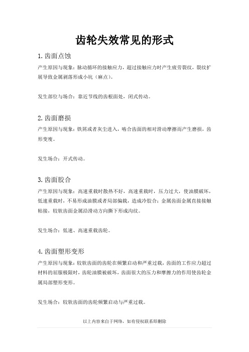
齿轮失效常见的形式
1.齿面点蚀
产生原因与现象:脉动循环的接触应力,超过接触应力时产生疲劳裂纹,裂纹扩展导致金属剥落形成小坑(麻点)。
发生部位与场合:靠近节线的齿根面处,闭式传动。
2.齿面磨损
产生原因与现象:铁屑或者灰尘进入,啮合齿面的相对滑动摩擦而产生磨损,齿形变廋。
发生场合:开式传动。
3.齿面胶合
产生原因与现象:高速重载时散热不好,高速重载时,压力过大,使油膜破坏,低速重载时,不易形成油膜或者局部偏载,造成冷胶合;金属齿面金属直接接触粘接,较软齿面金属沿滑动方向撕下形成沟纹。
发生场合:低速、高速重载齿轮。
4.齿面塑形变形
产生原因与现象:较软齿面的齿轮在频繁启动和严重过载,齿面的工作应力超过材料的屈服极限时,齿轮油膜被破坏,齿面很大的压力和摩擦力的作用使齿轮金属局部塑形变形。
发生场合:较软齿面的齿轮频繁启动与严重过载。
5.轮齿折断
产生原因与现象:疲劳断裂、过载折断、随机折断;
疲劳折断:齿轮在工作过程中,齿根处产生的弯曲应力最大并且集中,当轮齿重复受载后,齿根圆角处就会产生疲劳裂纹,并逐步扩展,致使轮齿疲劳折断轮齿。
过载折断:因短时过载或冲击过载而产生的折断。
发生场合:开式齿轮传动和硬齿面闭式齿轮传动。
发生后果:不能正常转动,甚至造成重大事故。
齿轮的失效形式
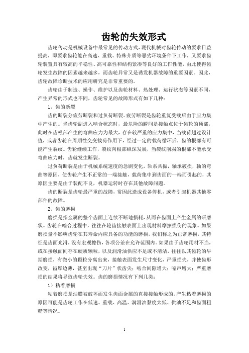
齿轮的失效形式齿轮传动是机械设备中最常见的传动方式,现代机械对齿轮传动的要求日益提高,即要求齿轮能在高速、重载、特殊介质等恶劣环境条件下工作,又要求齿轮装置具有较高的平稳性、高可靠性和结构紧凑等良好的工作性能,由此使得齿轮发生故障的因素越来越多,而齿轮异常又是诱发机器故障的重要因素。
因此,齿轮故障诊断技术的应用研究是非常重要的。
齿轮由于制造、操作、维护以及齿轮材料、热处理、运行状态等因素不同,产生异常的形式也不同,齿轮常见的故障形式有如下几种:1、齿的断裂齿的断裂分疲劳断裂和过负荷断裂。
疲劳断裂是齿轮重复受载后由于应力集中产生的。
当齿轮副进入啮合状态时,最危险的瞬间是接触点位于齿轮的顶部,此时在齿根部产生的弯曲应力为最大,存在较严重的应力集中,当载荷超过设计值,或者齿轮在周期性交变载荷作用下,经过一定的载荷循环后,齿的根部有可能产生裂纹。
齿轮继续工作,裂纹向根部纵深发展,当裂纹削弱的根部不能承受弯曲应力时,齿就发生断裂。
过负荷断裂是由于机械系统速度的急剧变化,轴系共振,轴承破损,轴的弯曲等原因,使齿轮产生不正常的一端接触,载荷集中到齿面的一端而引起的,其原因主要是由于装配不良,机器运转时存在其他故障问题。
齿的断裂是齿轮最严重的故障,常因此造成设备停机,或者引起机器其他零部件的故障。
2、齿的磨损磨损是指金属的整个齿面上连续不断地损耗,从而在齿面上产生金属的研磨状。
齿轮在啮合过程中,往往在轮齿接触表面上出现材料摩擦损伤的现象。
如果磨损量不影响齿轮在其寿命内应具备的功能的磨损,我们称之为正常磨损,其特征是齿面光滑,没有宏观擦伤,各项公差在允许范围内。
如果由于齿轮用材不当,或在接触面间存在硬质颗粒,以及润滑油供应不足或不清洁,往往以其齿轮的早期磨损,有微小的颗粒分离出来,接触表面发生尺寸变化,严重损失,并使齿形改变,齿厚边薄,甚至出现“刀片”状齿尖;啮合间隙增大;噪声增大;严重磨损的结果将导致齿轮失效。
- 1、下载文档前请自行甄别文档内容的完整性,平台不提供额外的编辑、内容补充、找答案等附加服务。
- 2、"仅部分预览"的文档,不可在线预览部分如存在完整性等问题,可反馈申请退款(可完整预览的文档不适用该条件!)。
- 3、如文档侵犯您的权益,请联系客服反馈,我们会尽快为您处理(人工客服工作时间:9:00-18:30)。
FAILURE PROBABILITY OF GEAR TEETH WEARMilosav OgnjanovicUniversity of BelgradeFaculty of Mechanical EngineeringABSTRACTIn extreme gear service conditions some of the tooth damages such as pitting are not the main type of teeth flank failure any more. The hypothesis concerning infinite fatigue endurance of teeth flanks is without support now. Abrasive wear and squeeze at local points of contact eliminate and/or stop pitting from developing. Three types of surface damages (abrasive wear, squeezing and pitting) occur simultaneously and contribute to each other. In that way, teeth flank failure accelerates and gets more intensive and progressive. Infinite flank endurance does not exist. Besides this, the process of simultaneous (progressive) teeth flank damage is stochastic. Statistical approach to failure intensity evaluation is the only possibility. For certain wear limits of teeth flanks, experimental results are presented by statistical parameters. Those statistical models and statistical parameters are suitable for the development of reliability models of gear and gear drives.IntroductionIntensive research in the area of the gear damage resistance is resulted with standard DIN 3990 part 5. This standard defines gear testing procedure and endurance limits for different kinds of materials and gear heat and mechanical treatments. Research in this direction is continued [1], [4], but many questions in that very complex area are still without answer. Gear calculation according to the mentioned standard is based on teeth pitting resistance. Fatigue of surface layer (pitting) is the most suitable for the load capacity calculation. In the service conditions and in the testing using FZG gear tester (DIN 51 354), it is not possible to extract fatigue (pitting) damages separately from the others surface damages (sliding wear, surface squeezing, etc.). Besides this, the processes like sliding wear (scoring and scuffing) and surface squeezing obstruct a pitting process. In these conditions, the gear teeth failure process can be slowed down (weakened) or accelerated. For this interaction, it is necessary to research and separately test a pitting process, for example, by using the ZF roller test rig [5] or perform especially those tests which can extract separate (not mixed) types of teeth failure [6]. Detailed research of teeth sliding wear is presented in the paper [2]. The wear depth of the teeth flanks is calculated by using a developed mathematical model.Complex teeth surface failure is not possible to be defined in a deterministic way. Interaction of individual damage processes is not the same for different stress levels, for different materials, heat and mechanical treatment or lubrication. This interaction is stochastic and can be presented by statistical models and parameters. In this paper, a suggestion in that sense is presented. It is not possible to define complex teeth surface failure in a deterministic way.Types of Teeth Wear and Wear Components SeparationThe gear load capacity is limited by different kinds of teeth flanks wear: pitting, abrasive and adhesive wear (scoring and scuffing) and squeezing. These flank damages are parallel or complementary. For pitting development, it is necessary to start the crack and grow it up along with increrased high stress cycles number. In the meantime, by sliding or squeezing it is possible to eliminate cracks in the very initial period and slow down the pitting process (especially micro pitting). Each of the mentioned damages can be disturbed or supported by some of the others. Pitting is the damage which corresponds to the gears with surface hardened teeth, at surface stress close to surface endurance limit. Sliding wear (scoring) is characteristic for the gears with non-hardened teeth and with high surface stress. The process of sliding wear is not limited by surface endurance limit. There is no stress level which cannot make surface damage along unlimited stress cycles number (teeth mesh revolution). Scuffing is damage characteristic for highly loaded gears with a very high speed of rotation. Squeezing of gear teeth flanks can arise with not hardened materials caused by a very high flank stress level, especially at a low speed of rotation. More details for each of the mentioned types of teeth flank wear are as follows. The mentioned types of teeth flank wear will be considered in detail.Conditions for Teeth PittingPitting is the result of the fatigue process in the teeth surface layer. Cracks (Fig. 1) can start between roughness of the surface layer or under the surface layer. According to the Hertzian pressure, the stress maximum is below the surface layer (Fig. 1a). The oil layer affects the reduction the Hertzian pressure and allows to displace point of maximal pressure to the surface (Fig. 1b). It is possible to conclude that in the case of better lubrication the cracks initiate between surface roughness. For this phenomenon, it is necessary to have a high number of stress cycles, i.e. a high level of teeth mesh revolution. The roughness and profile deviation, by micro pitting (Fig. 1b), firstly increase and then some of them grow up and divide (fractured) smaller or larger pieces from the flank. This process can be stopped or slowed down by elimination of micro pitting by sliding wear. In the case of poor lubrication (Fig. 1a), the cracks initiate under the surface layer and need a lesser number of stress cycles (teeth mesh revolution). These cracks can grow up till the very large size and it is difficult to eliminate them by sliding wear. This kind of pitting (Fig. 1a) can occur after a relatively small number of teeth mesh revolutions (mild materials) and after a much higher number of teeth mesh revolutions for surface hardened steels [3][9][10].The load level affects the surface pressure value. High flank pressure can succeed pitting cracks. At the same time, high pressure can eliminate lubricant between the flanks and succeed sliding wear, which can eliminate initial cracks. For this reason, better conditions for pitting development exist if the contact stress is not much higher than the endurance limit σHlim. Pitting test planning has to include the stress levels lower than the endurance limit, stress levels in the endurance limit range and in the stress ranges not much higher than the endurance limit.Thermal treatment of the teeth surface layers is an important condition for intensity of pitting development. The teeth without surface heat hardening are exposed to sliding wear from the beginning of the service. This wear reduces roughness and pitting cracks in the initial period of micro pitting development. In addition to this, the gear service life is limited by sliding wear. The teeth mesh revolutions during this short service life are not sufficient for the occurrence of fatigue cracks and their development. If the load (surface stress) is higher the sliding wear are more intensive. Conditions for the occurrence of pitting get worse and the pitting probability is smaller. On the other hand, hardened surfaces, for example, carburized teeth are very resistant to sliding wear, the stress cycles number in the service life is very high. This high stress cycle number is enough for pitting development. The pitting probability gets higher if the flank stress level is about the endurance limit. This is an additional condition for pitting development. Taking all this into consideration, pitting probability of hardened teeth is much higher in comparison with not hardened teeth.a)b)Figure 1. Teeth pitting:a) Hertzian stress distribution and pitting developmentb) Lubricant effect at stress distribution and pitting developmentFigure 2. Failure probability distribution of the gears failed by pittingTeeth Sliding Wear ConditionsThe gear teeth sliding speed is depends on the contact point position. In the middle of the teeth flank, the speed is close tozero and at the ends of the flank it is maximal. Sliding wear is also proportional to the contact stress [2]. Surface hardenedteeth are resistant to sliding wear, especially carbonized teeth. The effect of sliding wear in this case is very small. Nothardened teeth are not resistant to any type of wear. Sliding wear (especially scoring) is proportional to the sliding speed alongthe flank (Fig. 3a). The gears without surface hardening are not resistant to pitting wear either, but intensive sliding wearprevents development of surface cracks into full pitting. Figure 4 presents the results of gear flanks endurance based onpitting resistance of not hardened materials. These data can be obtained by the ZF rolling rig. As the sliding slows down thepitting process, not hardened teeth are predominantly damaged by sliding wear. Besides this, sliding resistance is not limitedby the endurance limit. That is the reason why this presentation is without the horizontal part of the endurance line. Gear teethmade of not hardened steels are predominantly damaged by sliding wear.a) b)Figure 3. Teeth sliding wear:a) Sliding speed and wear distributionb) Sliding wear damage of a gearFigure 4. Failure probability distribution of the gear sliding wearThe conditions which can accelerate and succeed teeth sliding wear are lower flank hardness, higher sliding speed, poor lubrication and metal particles present in lubricant. Sliding wear is a continual process which starts from the beginning of the gear service. Surface fatigue cracks which can provoke pitting damage are eliminated by sliding and particles can succeed scuffing damage. The only cracks which can be developed and cause pitting damage are subsurface cracks which are peculiar to poor lubrication [7][8].Teeth Squeeze ConditionsTeeth squeezing is failure typical for the gears made of steels of small hardness and exposed to high surface stresses. Figure 5a shows squeezing damage in the middle of the teeth flank. At the end of the flank there is the action of strong friction forces which produce high shearing stress. A combination of a normal contact stress and a shearing stress creates more effective surface plastic deformation in this flank region (Fig. 5b).a)b)c)Figure 5. Teeth squeeze:a) Squeeze in the middle of teeth flank,b) Squeeze at teeth addendum areac) Example of a gear damaged by squeezingProgressive Teeth WearCombination of different kinds of teeth wear with very intensive metal losing (weight reduction), is progressive teeth wear. Intensive teeth scoring at the beginning of the work eliminates flank surface roughness and makes a very smooth flank. At the same time, this process eliminates micro pitting between the roughness. The pitting process is disturbed and the fatigue stress cycles number for high stresses is higher in comparison with pure pitting (compare diagrams in Fig. 7). For the lower stress levels, the fatigue process needs higher stress cycles numbers. Particles relished by pitting, make damage process more intensive (scuffing) in comparison with pitting produced by surface fatigue. This is a combination of pitting and scuffing which wears more material from gear flanks. A hardened layer can be partly or completely eliminated. The soft teeth inside the material and roughness made by pitting and scuffing are liable to squeezing, especially in the area of high stresses. The squeezing process slows down the fatigue (pitting) process and accelerates the scuffing process along the whole teeth flank (Fig. 6).Figure 4. Progressive teeth wear – combination of pitting, scuffing and squeezingFailure Probability and Reliability ModelingThe first feature of a progressive wear process is stochastic behavior combined of a few elementary wear processes. The second one is that in the service life very severe working conditions are not continual. Periodical service conditions may be presented by the probability of these conditions p. By combining the failure probability P R of progressive teeth wear and the probability of service conditions p, it is possible to obtain the complex probability F p=pP R which defines the probability of progressive wear in service life.The failure probability is obtained by gear wear testing using the FZG gear tester (back to back system) or another similar system for gear loading and long time testing. Figure 7 presents the results of gear testing in planetary gear drive tested in a back to back system similar to the FZG gear tester. The lower boundary of failure probability distribution is defined by the visible flank failure beginning (10% failure). The upper boundary is defined by the thickness of the layer of teeth flank wear of 0,3 m (m – gear module). Gear teeth is surface hardened and the hardened layer is eliminated by a progressive wear process. Some of the points are obtained by the testing and some of them are defined by approximation. For a more precise definition, it is necessary to perform a number of tests, which will be done in the future. The results presented are compared with the gear endurance limits available in the DIN 3990 for the surface hardened and not hardened steels.Figure 7. Failure probability of progressive teeth wearBy using the lines of lower and upper failure boundaries, it is possible to obtain Weibull's functions of the failure probability P R . The function of the stress cycles number (teeth mesh revolution) P R (N) can be defined for every level of the stress σHN . For every stress cycle number N (teeth mesh revolution) it is possible to define the following function P R (σHN )()βη⎟⎟⎠⎞⎜⎜⎝⎛−−=N R e N P 1; ()βησσ⎟⎟⎠⎞⎜⎜⎝⎛−−=HN eP HN R 1 (1)2600240022002000180016001400 12001000800600400 105 106 107 108 109 1010 1011NσH N N /m m 2The parameters of the Weibull's function η and β are defined by using a coordinate of the points from the boundary lines which include the failure probability 0.1 and 0.9. For example, at the stress level of 1421 N/mm2, parameters η =2.5.108 and β=1.5, i.e.()5.1105.281⎟⎟⎠⎞⎜⎜⎝⎛⋅−−=NRe NP (2) Opposite of this, for the number of cycles to failure N=1.197.108, using diagram in Fig. 7, η=1618N/mm2 and β=8.51, i.e.()51.816181⎟⎠⎞⎜⎝⎛−−=HσH R eσP (3)In the same way it is possible of the every (each) stress level or failure cycle number to define the Weibull's functions of failure probability P RConclusionsGear load capacity calculation is defined according to the pitting of the teeth flanks. In service conditions, a failure process is combined of a number of damage processes. Which of them will be prevail depends on design parameters, technological and exploitation conditions. Periodically, for some of gears, extremely difficult service conditions exist, which creates a possibilityfor progressive teeth wear. A process of progressive teeth wear is presented in the paper.Every type of flank failure corresponds to defined conditions (service, design, technology,…). Results of progressive wear are obtained by experiments. For these results, failure boundaries which can be used for parameters of Weibull's function definition, for different stress levels and for different stress cycles numbers (teeth mesh revolutions) have been defined. For amore precise failure probability definition, it is necessary to perform a great number of teeth failure tests.References1. Hohn B.R., Winter H., Laboratories at Work: Institute for Machine Elements, Gear Research Centre (FZG), Tribologyjournal 3-3, pp 325-340, 19972. Floding A., Andersson S., Simulation of Mild Wear in Spur Gears, Wear, Vol.207, pp 16-23., 1997.3. James,Li. C., Limer J.D., Model-based Conditions Index for Tracking Gear Wear and Fatigue Damage, Wear 241, pp 26-32., 2000.4. Hohn B.R. , Modern Gear Calculation, - Proceedings of the International Conference on Gears, VDI-Berichte 1665, pp 23-43., 2002.5. Joachim F., Kurz N., Glatthaar B., Influence of Coatings and Surface Improvements on the Lifetime of Gears, -Proceedings of the International Conference on Gears, VDI-Berichte 1665, pp 565-582., 2002.6. Podgornik B., Vižintin J., (2002), Wear Reaistance of Plasma and Pulse Plasma Nitrided Gears, - Proceedings of theInternational Conference on Gears, VDI-Berichte 1665, pp 593-601., 2002.7. Weck M., Hurachy-Schonwerth O., Bugiel Ch., Service Behaviour of PVD-Coated Gearing Lubricated with BiodegradableSynthetic Ester Oils, - Proceedings of the International Conference on Gears, VDI-Berichte 1665, pp 677-690., 2002.8. Ding Y., Rieger N.F., Spalling Formation Mechanism for Gears, Wear 254, pp 1307-1317., 2003.9. Aslantas K., Tasgetiren S., A study of Spur Gear Pitting Formation and Life Prediction, Wear 257, pp 1167-1175., 2004.10. Komuri M., Kubo A., Takahashi T., Tanaka T., Ichihara Y., Pitting, Chipping and Tooth Breakage due to Edge Contact, -Proceedings of the International Conference on Gears, VDI-Berichte 1904.2, pp 1309-1324.,2005.。