电子围栏说明书英文版
G5S系列电子围栏说明书
亲爱的用户,欢迎您选用广拓电子围栏。
谨此感谢!为了使您更方便使用,请仔细阅读说明书,并按照说明书步骤操作,同时特别注意说明书中所有的警告和注意事项。
请妥善保存此说明书。
由于产品的改进,您所得到的电子围栏产品可能与说明书中图示不完全一致,请以实际产品为准,谨此致歉。
●本产品工作时内部带有高压,为避免电击伤害请勿私自拆装;●产品输出端和前端有5000V~10000V高压,在产品工作状态下,切勿触摸;●切勿在雷电期间安装电子围栏;●切勿将脉冲主机直接安装于潮湿场所。
●本产品一旦出现异常情况,应先切断电源,并及时通知专业安装或检修人员。
切勿自行拆修,否则后果自负;●用户不得自行打开主机维修,否则我方不予保修;●本产品的使用者,必须具有电器安全及触电解救知识;●安装使用前请阅读此说明书,熟悉本产品的正确使用方法并规范操作,否则产生的一切后果,由使用者承担。
目录一、功能与特点 (3)二、技术参数 (4)三、脉冲主机的说明及应用 (5)四、前端围栏的选型 (13)五、前端围栏的安装 (14)六、使用与维护 (20)七、简单故障排除方法 (21)八、布线案例 (20)一、功能与特点G5S系列脉冲电子围栏主机属于第四代网络电子围栏产品。
他把阻挡、威慑、报警、智能显示和联网远程控制等功能有机地集成在一起,是一种崭新的智能型周界阻挡安防报警产品。
针对传统模式电子围栏短路同根导线或脉冲间隔内触发不报警的弊端问题,通过先进的技术,解决当前行业难题,实时智能监控围栏工作状态,引领电子围栏行业领域革新的新潮流。
G5S系列脉冲主机有以下主要功能特点1.1网络光纤通讯接口:主机内置光口模块和网络模块,可以与光纤和网络进行直连通讯,比外置光端机及网络模块方式更稳定可靠。
1.2远程控制:通过控制键盘远程实现定时布防、撤防,电压调节,报警输出延时时间调整等关键参数的调整和控制。
1.3多级联网:通过控制键盘或控制软件,可实现多级联网。
1.4BI-Polar:独有BI-Polar技术,可实现前端围栏上每根线都有高压脉冲电,让入侵者无机可乘。
牧场电子围栏说明书
原因
输出指示灯亮,防护线不通电
请确认本机器输出端的高压线是否和防护线 接触良好以及地线的接地情况。
按下电源开关,夜间模式灯不亮
确认电池正负极放置情况;也可能是因为电
池电能耗尽请考虑更换新电池
夜间模式灯亮,输出灯不亮
不是夜间,无法工作
请确认周围是否有光源照射到机器上,若有,
请调整机器感光器,避免受光。 在白天操作时请避免日光直射到感光器上
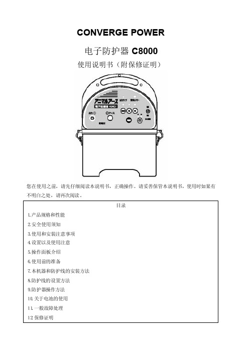
5.操作面板介绍
感光器:感知周 围的光线,进行 日夜制动
输出切换开关: 切换输出电压的 强弱
地线端口:接地 线
电源开关:按一次电源接
通,再按电源切断 注意:绝对不要将导线正负 极反接,有可能造成故障
黑色为负极 红色为正极
电池按钮:电池状 态良好时亮绿灯, 不良时红灯
制动模式:【夜】仅在夜间启 动【昼】 只再白天启动【连续】昼夜制动
*请一定要使用同一品牌的干电池。 ●避免电池置于暴晒,高温,潮湿场所,请放置于常温地方 ●请将使用完电池座位不可燃垃圾处理。
11.一般故障处理
请不要擅自拆装,改造本机器,如需修理,请与购买商家商量应对。
若有故障,请先参照下列情况。
状态
输出指示灯
DC2000V 以上灯亮
电池指示
DC7V 以上:绿灯亮 不足 DC7V:红灯亮
干电池(寿命)
弱:大约 30-40 日(每天使用 12 小时)根据使用情况有变化
外形尺寸
(约)宽 210*长 160*高 290mm(不包括左右的固定金属架)
重量(不含电池)
(约)2kg
附件
连接控制部分底部
电源连接端子
电子围栏主机说明书
深圳市华俊信科技有限公司电子围栏说明书●使用前请仔细阅读本说明书●本说明书适用于电子围栏主机系列产品●本说明书包含服务指南,请务必妥善保管目录第一章产品介绍.................................................................................................................................................... - 1 -1.1产品设计依据............................................................................................................................................ - 1 -1.2产品特性.................................................................................................................................................... - 1 -1.3产品技术参数............................................................................................................................................ - 2 -1.4 LED/LCD指示灯状态说明...................................................................................................................... - 2 -1.5控制器主机正面、底部接线说明示意图................................................................................................ - 3 -1.6控制器主机功能端接线说明(见上图)................................................................................................ - 5 -1.7主机前段施工示意图................................................................................................................................ - 6 - 第二章主机调试与报警试验................................................................................................................................ - 8 -2.1通电检查.................................................................................................................................................... - 8 -2.2报警试验.................................................................................................................................................... - 8 - 第三章使用与维护................................................................................................................................................ - 9 -3.1 检查........................................................................................................................................................... - 9 -3.2 蓄电池管理............................................................................................................................................... - 9 -3.3 常见问题处理........................................................................................................................................... - 9 -3.4 注意事项................................................................................................................................................... - 9 -3.5使用.......................................................................................................................................................... - 10 -3.6 日常维护................................................................................................................................................. - 10 -第一章产品介绍1.1产品设计依据GB/T7946-2008《脉冲电子围栏及其安装和安全运行》JB/T5163-2007《中华人民共和国机械行业标准》1.2产品特性电子围栏系统,就是在非出入通道的周边区域设置脉冲电子围栏探测器,形成一道电子围墙进行防范和管理。
EMX电子围栏使用手册(新版)
第 1 页 共 24 页电子围栏使用说明感谢您选择我们的EMX 电子围栏产品!为安全、正确、有效地安装、使用EMX 电子围栏系统,请在安装使用前先阅读本使用手册。
目录安全注意事项 (3)一、脉冲主机选型 (4)二、脉冲主机安装 (4)三、技术参数 (6)四、前端围栏的设计要求 (6)五、前端围栏配件的安装 (11)六、使用与维护 (15)第 2 页共24 页安全注意事项●切勿在雷电期间安装电子围栏●切勿将多脉冲主机主机直接安装在潮湿场所●除非电子围栏已解除高压,否则切勿触摸系统导体部分。
●在安装使用本产品之前,对工作人员应预先做好安全教育,技术培训。
●本产品在通电状态下工作,内部带有AC220V、50Hz电压,产品的输出端和电子围栏上带有≤10KV的脉冲高压。
应避免人为触及,确保安全。
●本产品的使用者,必须具有电器安全知识,经过专业培训,熟悉本产品的正确使用方法。
●本产品一旦出现异常情况,应先切断电源,再作检查分析,防止故障扩大,按规定保修。
●应防止植物沿合金丝向上生长,合金丝与植物间的最小距离为20cm(从植物摇摆时的最近位置计算)。
●不准在电子围栏上接入交流电源。
当产品发生故障时,应保证电子围栏不带交流电。
●本产品符合国家安全标准,具有能量电荷控制,不会直接造成人身伤害。
第 3 页共24 页第 4 页 共 24 页一、脉冲主机选型EMX 电子围栏系统由脉冲发生器(主机)、前端(电子围栏)和报警输出设备等部分组成,主机产生脉冲高压供给电子围栏,当电子围栏被破坏时,主机发出报警,它是周界报警的一种,有威慑、阻挡、报警等功能,主要应用在变电站、别墅(小区)、军事设施、仓库、机场、工厂等周围,防范入侵。
根据所选防护等级设计要求或客户自身需要,选择合适的脉主机机型。
主机选型1主机 01(Speedrite2)主机选型2主机02(K-II)第 5 页共24 页第 6 页 共 24 页主机选型3主机03(speedrite-emx )接线图如下:第 7 页 共 24 页主机选型4主机04(speedrite-extra )接线图如下:二、脉冲主机安装安装场所:●控制中心●门卫●现场(安装在现场,需将主机放在防护箱内。
电子围栏方案与说明书

脉冲电子围栏安装及使用说明书目录安全注意事项 (2)一、脉冲电子围栏主机概述 (2)二、脉冲电子围栏主机特点及性能指标 (2)2.1 产品功能特点 (2)2.2 工作环境指标 (3)2.3 输出脉冲指标 (3)三、脉冲电子围栏主机及周界安装说明 (3)3.1 高压脉冲围栏主机图示及接线说明 (3)3.2 LED指示灯状态说明 (4)3.3 周界安装前期准备工作 (4)3.4 周界安装说明及安装过程描述 (5)四、脉冲电子围栏主机使用说明 (10)4.1 脉冲电子围栏主机测试 (10)4.2 使用脉冲围栏主机的RS485通信功能 (10)五、PC 控制界面安装及使用说明 (10)5.1安装 (10)5.2系统设置 (11)5.3选择 (12)5.4 用户管理 (12)5.5报表打印 (12)5.6帮助 (12)5.7 主界面 (12)六、键盘使用说明 (13)6.1 键盘内部接线图 (13)6.2 键盘开机与关机 (13)6.3 按键说明 (13)6.4 通过界面设置围栏及本键盘参数的操作 (14)6.5 关闭窗口轮询 (15)6.6 键盘告警说明 (15)6.7报警记录 (15)七、施工安装规范及安全注意事项 (15)7.1施工安装规范 (15)7.2施工中应注意的其他问题 (15)尊敬的客户:您好!感谢您使用本产品,为了更好更快的安装及使用本产品,请在使用前认真仔细地阅读本手册。
脉冲电子围栏系统包括脉冲电子围栏主机以及对其控制的PC 主机、键盘主机, 本手册针对脉冲电子围栏主机适用,如是您有任何技术问题或需要技术支持,请联系我公司,我公司将竭力为您服务。
安全注意事项◆除非电子围栏已解除高/低压输出,否则切勿触摸系统导体部分。
◆切勿在雷电期间安装电子围栏。
切勿将控制器直接安装于潮湿场所。
◆在安装使用本产品之前,对工作人员应预先作好安全教育技术培训。
◆安装本产品过程中,为了产品以后的正常使用,产品的接地一定要严格按照说明书要求。
电子围栏说明书 v1.1
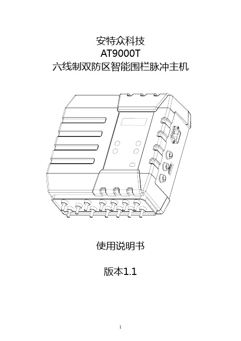
安特众科技AT9000T六线制双防区智能围栏脉冲主机使用说明书版本1.11.前言感谢您选用安特众(ATIZON)六线制双防区电子围栏脉冲主机。
为了方便您正确的使用该产品,请仔细阅读说明书,并确实了解产品各项相关性能后,再安装使用;请特别注意说明书中所有的警告和注意事项,并妥善保存此说明书。
由于产品的改进,您所购买的电子围栏脉冲主机产品可能与说明书中图示细节不完全一致,请以实际产品为准。
本产品最终解释权归安特众科技有限公司所有。
1.1安全注意事项●在安装使用本产品之前,对工作人员应预先做好技术培训和安全教育。
●本产品工作时,主机内部带有AC220V(50Hz)电压,前端围栏上带有1000V~9000V脉冲高压,切勿触碰。
●切勿在雷电期间安装电子围栏。
●切勿将脉冲主机直接安装于潮湿场所。
●确保在使用本产品前,您已获悉本手册的全部内容。
●本产品的使用者,应具有一般的电器安全知识,安装使用前详细阅读此说明书,熟悉正确使用方法并规范操作;否则产生的人为故障或事故,由使用者承担。
●本产品一旦出现异常情况,应先切断电源,并及时通知专业安装或检修人员;切勿自行拆修,否则后果自负。
2.功能与特点电子围栏脉冲主机将阻挡、威慑、报警、通讯、智能显示等功能有机地集成在一起,是一种崭新的智能型周界防盗报警产品。
2.1传统功能1、阻挡性,威慑性;前端实体围栏对入侵者有阻碍功能,自身带有高压脉冲电,同时对入侵者形成极大的威慑力。
2、无盲区、无死角;前端是有形的围栏,不受地形高低和曲折程度的限制,可以随着地形的变化任意架设,达到不疏不漏的效果。
3、报警、通讯、联动功能;脉冲主机的报警输出信号能与其他安防设备联动,从而提高整个系统的安全防范等级。
4、设计灵活性、智能判别性;前端围栏系统可根据用户要求、现场地理环境和安全等级进行设计和安装,做到每个项目都有其量体裁衣的独特性;能够智能检测各种侵扰的级别,智能区分动植物干扰和人为入侵,误报率极低。
电子围栏设备说明书

Learn more about fencing by visiting our websites at: FOR OPTIMAL RESULTS, WE RECOMMEND YOU HAVE THE FOLLOWING:1. Electric Fence Tester 2. Three 6-8’ Ground Rods3. Battery Tester (For DC and Solar)4. Three Ground Rod Clamps5. 2 Two Lengths 20 KV Insulated Hook-up Wire (one long enough to connect to fence energizer to ground system and one long enough to fence energizer to fence line)WARNING: THE FOLLOWING CAN RESULT IN DECREASED FENCE PERFORMANCE1. Brush, weed and plant growth around the base of your fence.2. Improper grounding.3. Snow.4. Cracked or broken insulators.5. Fence wires that are less than 4” apart.6. Dry, rocky or sandy soils.7. Insu ciently charged battery.☐WARNING: Read ALL these instructions. Only use electric fence energizer products for the purpose intended as de ned in this manual.☐This controller must be grounded. If it should malfunction or break down, grounding reduces the risk of electrical shock by providing a path of low resistance for the electric current. Grounding this product is provided by properly installed ground rod electrically connected to the fence controller output ground terminal.☐To reduce the risk of electric shock, an AC line operated fence controller has an polarized plug (one blade wider than the other). This plug will t in a polarized outlet only one way. If the plug does not t fully in the outlet, reverse the plug. If it still does not t, contact a quali ed electrician to installthe proper outlet. Do not change the plug in any way.☐To reduce risk of electrical shock do not remove cover. Refer to service personnel.☐Never electrify barbed wire! The barbs may injure animals if they become tangled in the fence.☐Always disconnect battery-powered fence controllers from the battery before recharging the battery. Failure to do so may damage your fence controller and battery charger, and void your warranty.☐Never run more than on fence controller on the same fence line at one time. The pulses of short shock solid state fence controllers will be too close together and may be hazardous to animals and people. It will also damage your fence controllers.☐Instruct all persons how to disconnect a fence controller in case of emergency. Post signs on electric fences along public roads or near residences.☐Never disconnect wires or approach a fence during lightning storms.☐WARNING: Risk of electric shock! Do not connect an eletric fence to any other device such as a cattle trainer or a poultry trainer. Otherwise lightning striking your fence will be conducted to all other devices.☐Never connect a DC fence to an AC power supply.☐WARNING: Energizers requiring an external ground must be properly grounded.☐WARNING: Many AC energizers are internally grounded and are equipped with polarized 2 prong plugs. These plugs must never be altered and must be inserted into a properly installed, appropriate outlet. Only use a polarized extension cord. Damaged polarized plugs must be replaced with polarizedplugs. failure to follow this warning could create a safety hazard, damage the energizer, and void the warranty.☐Install fence lines powered by seperate fence energizers far enough apart to prevent contact with both fence lines at the same time. Simultaneously touching two fences powered by seperate energizers could be hazardous.☐Install fence lines powered by seperate fence energizers far enough apart to prevent contact with both fence lines at the same time. Simultaneously touching two fences powered by seperate energizers could be hazardous.☐In a double-insulated energizer, two systems of insulation are provided instead of grounding. No means of equipment ground is provided in the supply cord of a double-insulated energizer, nor shoulda means for equipment grounding be added to the energizer. Servicing of a double-insulatedenergizer requires extreme care and knowledge of the system, and should be done only by a serive personnel. Replacement parts for a double-insulated energizer must be identical to the parts they replace.IMPORTANT: Mount inside or in a waterproof enclosure (Required for AC Energizers)AC/DC Inside installationSheltered InstallationInstallationSolar T-Post Installation (applicable for speci c models)Solar Wood Post Installation (applicable for speci c models)Solar Wood Post InstallationSTEP 4: Connect to Fence LinePoly tape connectionAluminum/Steel/Poly wire connectionSTEP 5: Power Fence EnergizerNOTE: Fence energizer will be outputting voltage at this point - to avoid shock do not touch fence terminal orWoodstream gaurantees your satisfaction. You can return product with it receipt to the place of purchase within 30 days for a full refund. Proof of purchase is required for a full refund.LIMITED WARRANTYWoodstream warrants energizers based on their milage rating from the date of purchase (or date of manufacture if proof of purchase is not provided) against defects in materials and workmanship, and from damage caused by lightning. Visit our website at www. to learn more about the warranty that applies to the speci c energizer purchased.For any sized energizer, retain your receipt for proof of purchase or register your energizer online at immediately after purchase. Also, please reference the web page for a list ofCerti ed Repair Centers and instructions on returning fence controllers for service.TERMS APPLICABLE TO BOTH 30-DAY RETURN POLICY AND THE LIMITED WARRANTY. Neither the30-day return policy nor the limited warranty applies to any defect caused by improper installation,misuse, product alterations, tampering, neglect or any similar reason not related to product malfunctionsor defects in the materials or workmanship of the product. The 30-day return policy and the limited warranties are given only to the original purchaser of the product and not to any subsequent owners orto any other user or person when installed and used in accordance with the instructions found in theowner’s manual. No person is authorized to grant any warranty additional to or di erent from thiswritten warranty.To make a warranty claim, you must contact Woodstream Corp. at 800-800-1819 or regarding defective product or parts during the warranty period or contact one of the Certi ed Repair Centers listed on If you have not registered your energizer online immediately after purchase, you may need to provide additional information such as, your name, mailing address, proof of purchase date and a description ofthe problem. If the defect is covered by the limited warranty, Woodstream Corp. or a repair center willrepair or replace (at its option) the defective product or parts.NEITHER THE SELLER NOR THE MANUFACTURE SHALL HAVE LIABILITY FOR ANY ACCIDENTIAL OR CONSEQUENTIAL DAMAGES RESULTING FROM OR CAUSED BY ANY DEFECT, FAILURE OR MALFUNCTION OF ANY PRODUCT.Part # EC-ENGMANUALSERIAL NUMBER INFORMATIONThe serial number for all Woodstream Corp. fence energizers will go to a 12 digit serial number. The format for the 12 digit serial number is as follows:EC XX XX XX XXXXCategory Year Month Day Serial numberIf no sales receipt is provided with the return, we will use the date of manufacture shown in the serial number.Please contact Woodstream Corp. for all warranty claims or returns:Woodstream Corp.69 North Locust Street Lititz, PA 17543855-592-7322LIMITATION OF DAMAGESThe directions for use of this product should be followed carefully. It is impossible to eliminate all risk inherently associated with use of the product. The e ectiveness of Woodstream brands of fence controllers may depend on the e ectiveness of connections, interruption of power source, accidential grounding of wires, weatherconditions or the manner of use or application, all of which are beyond the control of Woodstream or the seller. All such risks shall be assumed by the buyer.Woodstream warrants that this product is reasonbly t for the purposes referred to in the directions for use, subject to the inherent risks referred to above. Woodstream makes no other expressed or implied warranty of tness or merchantability or any other expressed or implied warranty. IN NO CASE SHALL WOODSTREAM AND THE SELLER BE LIABLE FOR CONSEQUENTIAL, SPECIAL OR INDIRECT DAMAGES RESULTING FROM THE USE OR HANDLING OF THIS PRODUCT. WOODSTREAM AND THE SELLER OFFER THIS PRODUCT AND THE BUYER AND USER ACCEPT IT, SUBJECT TO THE FOREGOING CONDITIONS OF SALE AND WARRANTY WHICH MAY BE VARIED ONLY BY AGREEMENT IN WRITING SIGNED BY AN OFFICER OF WOODSTREAM.Some states, however, do not allow the exclusion or limitation of incidental or consequential damages, so the above limitation or exclusion may not apply to you. This limited warranty gives you speci c legal rights, and you may also have other rights which vary from state to state.。
电子围栏主机说明书
深圳市华俊信科技有限公司电子围栏说明书●使用前请仔细阅读本说明书●本说明书适用于电子围栏主机系列产品●本说明书包含服务指南,请务必妥善保管目录第一章产品介绍.................................................................................................................................................... - 1 -1.1产品设计依据............................................................................................................................................ - 1 -1.2产品特性.................................................................................................................................................... - 1 -1.3产品技术参数............................................................................................................................................ - 2 -1.4 LED/LCD指示灯状态说明...................................................................................................................... - 2 -1.5控制器主机正面、底部接线说明示意图................................................................................................ - 3 -1.6控制器主机功能端接线说明(见上图)................................................................................................ - 5 -1.7主机前段施工示意图................................................................................................................................ - 6 - 第二章主机调试与报警试验................................................................................................................................ - 8 -2.1通电检查.................................................................................................................................................... - 8 -2.2报警试验.................................................................................................................................................... - 8 - 第三章使用与维护................................................................................................................................................ - 9 -3.1 检查........................................................................................................................................................... - 9 -3.2 蓄电池管理............................................................................................................................................... - 9 -3.3 常见问题处理........................................................................................................................................... - 9 -3.4 注意事项................................................................................................................................................... - 9 -3.5使用.......................................................................................................................................................... - 10 -3.6 日常维护................................................................................................................................................. - 10 -第一章产品介绍1.1产品设计依据GB/T7946-2008《脉冲电子围栏及其安装和安全运行》JB/T5163-2007《中华人民共和国机械行业标准》1.2产品特性电子围栏系统,就是在非出入通道的周边区域设置脉冲电子围栏探测器,形成一道电子围墙进行防范和管理。
- 1、下载文档前请自行甄别文档内容的完整性,平台不提供额外的编辑、内容补充、找答案等附加服务。
- 2、"仅部分预览"的文档,不可在线预览部分如存在完整性等问题,可反馈申请退款(可完整预览的文档不适用该条件!)。
- 3、如文档侵犯您的权益,请联系客服反馈,我们会尽快为您处理(人工客服工作时间:9:00-18:30)。
Directory preface (2)safe note (3)一.function and feature (4)1.1 function (4)1.2 feature (4)二、instruction (5)2.1 design basis (5)2.2.characteristic (5)2.3 technical index (5)2.4 LEDindicated (5)2.5The front ,bottom of controller (6)2.6wire connection instruction (6)三、design requirement (6)3.1safety level (6)3.2 security (7)四、installation (7)4.1 install mode (7)4.2 install angle (9)4.3terminal rod/insulator install (9)4.4 middle rod/insulator install (10)4.5middle pull rod/insulator install (10)4.6 tensioner install (10)4.7lightning-arrester (10)4.8alloy wire connection (11)4.9grounding (11)4.10ground wirin g (11)五、controller install &connection (11)5.1controller install (11)5.2controller and fence connection (12)六、debug and alarm test (12)6.1 electrify check (12)6.2alarm test................................... .. (12)七、install rule & security note (15)8.1 install rule (15)8.2 safety note and some removing methods (16)Prefaceshanghai Yi Section Company is specialized in manufacturing electric security fence with its own R&D department factory located in Shenzhen.Yi Section company persistently follows the principle"do everything with whole hearted", through superior quality and zealous service, Yi Section tries every efforts to respond the users that gives uslong-term support and trust.Pulse electric fence energizer and perimeter accessory that Yi Section products and develops conforming to the requirements of GB/T7946-2008 《pulse electric fence installation and safe operation》and meet CEI-61011 international electric fence standard. The patent water proof casing design, professional output method, advanced difference voltage output technology, unique LCD display function, make the products as the leader in the industry. The products sell to Unite States, Europe, Australia, Africa, and Asian country , Yi Section will be the base of international production and service. The products are widely used in ware house, industry areas, power station, private house, villa, school, car parks, plant areas, airpot, prison, military base.etc.Security note:◆Unless high/low voltage output disarmed of electric fence, don’t touch the conductor part of the system.◆Don’t install electric fence during the thunder, don’t install controller in moist place.◆Before install and use the product, do the safe educational technology training work.◆During the installation, in order to use normally in future, follow the instructions to make sure the grounding of products. Refer to “4.9 item”◆When the product is electrified , the inside of controller is 220v 50Hz AC current, 5-10KV high voltage pulse on the output port and electric fence, don’t touch it to make sure security.◆The user must know the related electric device knowledge, and read the user instruction and operate it carefully before install it with correct use methods, otherwise , our side don’t bear any responsibility if any accident arise.◆Once abnormal case happen, should make sure the power off, then professional staffs check and analysis repair or contact our company, don’t repack it by your own.一.Function and featureThere are two kinds of existing security products. One kind is a fence, like traditional brick wall, cement wall, glass wall, iron fence and so on, has the obvious contours, encircles the defense area, has the impediment external invasion function, but does not have the alarm and the surveillance function. Another kind is the alarm system, like the infrared correlation alarm apparatus, divulge electric cable, CCTV and so on, they have the alarm or the surveillance function, but does not have the impediment function.The smart pulse electric fence system integrate the prevents and alarm functions together, and increase the high voltage deterrent effect, not only have visible fence, but also have smart multi-zone controller, the alarm system becomes brand new perimeter security system.1.1 system function1.1.1 have complete and explicit dividing line fence,and formidable impediment and deter function.1.1.2 have low rate of false alarm function,when the outer fence alarm,the display windows rapidly display which zone suffers break,short-circuit and tamper, reflect the current condition.1.1.3 The DC 12V alarm connection,dry contact signal output, can linkage with other security system, improve the system’s safe rank.1.1.4 distinction function of electric fence and can detect all kinds of invasion rank, can differentiate the accidental invade from forceful invade ability.The accidental intruder see the alarm or suffer from the electric shock, the leave, the alarm apparatus do not send out alarm. The intruder invade forcefully , so that the electric fence will be destroyed, in this case, the system will send out alarm. Only the intruder really invade and destroy the system, then will send alarm, will not alarm mistakenly and fails to alarm.1.2 system feature1.2.1Absolute safety and alarm perceiveThe traditional high voltage pulse electric net system doesn’t have alarm perceive function, only through high voltage, strong current to impediment intruder. It is very easy to get intruder disable, even dies and so serious results. The smart pulse electric fence system adopts low energy pulse high voltage((5~10KV),because the energy is extremely low,the response time is extremely short, will not cause the damage to the humanbody. Once touched, will just leave dut to electric shock.1.2.2The low rate of false alarm and strong AdaptabilityThe smart pulse electric fence system is not affected by environment (for example. trees, animals, shake.etc ) and climate ( wind, snow, rain and fog,etc) and not limited by terrain height and winding degree. The rate of false alarm is very low.1.2.3 impediment and alarm dual functionThe new concept of smart pulse electric fence system is to prevent the intruder out of from the fence area,without the crime is the goal, give the intruder one kind of deterrent feeling and impediment function, dare not act rashly, achieve the security, reduces the crime.1.2.4 continuous work,set armed/disarmed .1.2.5 use the 12V/4Ah battery as backup power supply,when the power supply is off,can work continually.1.2.6 According to user’s request and site geographical environment, carry out the design and installation, and workwith multiple modern security products, such as CCTV monitored system, television supervisory system andGSM system to improve the system security ranks.1.2.7 Absolute safety, conforms to the international CE certification and is also in conformity with IEC 60335-2-76 andthe GB/T7946-2008 request, and get approved from public security form test.二、product instructions2.1 product design basis:GB/T7946-2008 "Pulse electric fence installation And Safe operation"2.2 product characteristic:● difference voltage output technology: every wire has voltage, have the differential voltage between the two adjacent wires.●LCD display the monitor state indicating the voltage on every wire.● high/low voltage switch manually, long-distance equipment auto switch function.●short circuit, break and tamper alarm, equipment fault auto-detect..●waterproof casing and downward appearance design guiding the industry development.●RS 485 main line control, keypad, computer, network and multiple long distance management solution.●DC12V, open/close dry contact alarm output, can work with other modern security products..2.3 product technical index2.3.1 power supply: AC180V-240v 50Hz2.3.2 use environment2.3.2.1 Temperature :-40-+50℃2.3.2.2 moisture: :≤95%2.3.3 output index:Output peak voltage:5KV~10KVOutput low voltage: 700~1000VPeak current of pulse: <10APulse duration: ≤0.1sPulse interval time: 1sMax quantity of electricity of pulse: 2.5mCMax energy of pulse: ≤5.0JSystem power consumption: 10w2.4 LED indicated lamp condition instructions:2.4.1 AC 220V or DC12V,when power supply input ,the green indicated lamp is bright.2.4.2 when armed,the yellow indicated lamp is bright. When disarmed,it shows off.2.4.3 when alarm break,the red indicated lamp is bright.2.4.4 when alarm short circuit,the red indicated lamp is bright2.4.5 when open cover, the red indicated lamp of tamper is bright.2.5 the front and bottom of controller instructions.2.6 the wire connection of controller instruction( above drawing)2.6.1 the controller comprise two parts: input and output,the positive pulse from output part”1st line high voltage output port”transfer to fence wire, then return back to the receiver part “ 1st line high voltage input port”, negative pulse from output”2nd line high voltage output port” transfer to fence wire, then return back to the receiver part” 2nd line high voltage input port” ,so form positive and negative pulse closed circuit on the front fence.2.6.2 high voltage earth output: can share the same earth output with lightning arrester, strong/weak earth separate.2.6.3 voltage switch: use for switching high/low voltage mode or automatic working mode.2.6.4 keypad output: can connect keypad directly or RS485 transfer RS 232,then connect to computer by long distance control, The RS 485 connection of each controller needs to go hands by hands connection, multiple connection is not allowed.2.6.5 switch output: output open/close dry contact signal, needs to connect with other linkage device.2.6.6 alarm output: when alarm, output DC 12V voltage, connect with alarm device DC 12v below 10W.2.6.7 power switch: control the energizer on/off.2.6.8 power supply input: connect AC 220V power source.三、design request of electric fence3.1 according to different security rank, configurate suitable electric fence,usually divide into Ι、Ⅱ、III th e three rank.Ι—general security rank, uses 4 lines system, the monitor zone partition does not surpass 500 meters.Ⅱ—medium security rank, uses 8 lines system, the monitor zone partition does not surpass 250 meters.III—higher security rank, uses 12 lines system, the monitor zone partition does not surpass 100 meters.Every zone must configurate independent controller, and have different triggered alarm apparatus, can indicate the alarm zone number. The alarm output usually linkage with CCTV, red-infrared correlation, spotlight, alarm apparatus etc. When applied, the length of monitor zone should set according to the perimeter total length, the terrain and the objective site environment.3.2 Security3.2.1 don’t allow get the AC power supply on electric fence. when the product gets faulty, please make sure the electricfence without any AC power supply.3.2.2 product used the rectification voltage dropping DC 12V, then voltage-rise to condenser charge, finally electriccapacity pulse discharge boosting transformer, the output energy is limited by rectification, primary voltage-rise, electric capacitance discharge, so many links, without harm to human body and absolute safety.3.2.3 association factor and the influence of electric shock:The electric pulse will not injure the intruder, to avoid the associated responsibility, firstly, electric fence warning signs should hang up at every other 10 meters striking position noted” electric fence, forbid climbing”, secondly, the height of electric fence should be above 1.8meters, if the height of electric fence is not high, should install isolated netting or wall to avoid accident.3.2.4 electric fence should not be with other power circuit and telecommunication wires on the same pole.3.2.5 electric fence should keep a certain safe distance from the power circuit. The minimum distance as shown in thetable 3-13.2.6 horizontal distance between electric fence and public rod border should be above 5m( except the electric fence on top of the wall)3.2.7 electric fence has pulse high voltage, when bad connection or close to charged conductor, will have fire spark.Thus, electric fence should install without any flammable gas, and without any flammable fluid place. Accordingto the related national standard, keep enough safe distance, or take the safe measures to isolate.3.2.8 When inspect the place to install electric fence, pls make sure the electric fence without any conflict with theelectric wire, pipeline from the ground. And without any sundry goods at nearby place, whether the electric fence is influenced strongly by transmitting station and other high frequency device. If have, must mark the signal wire with STP shielded twisted pair at the construction drawing.四、Electric fence install4.1 install mode:4.1.1 install on top of the wall.Install the electric fence on top of wall, the height of fence wall should be above 1.8meters, the wire pole/rod may have welding ,clip or buried the three modes, should choose suitable mode according to the fence structure condition. For example, install at the steel fence, can take the welding, install at the concrete wall, can take buried mode to make sure stable, artistic, may use other modes also.4.1.2 The attached installThe installation attaches on the fence or top or inside, the fence wall directly withstanding the pressure and wire tension, before installation, pls make sure the structural strength of the wall, if unreliable, should reinforce in advance. The metallic conductor wire from the front end of electric fence spacing to the wall should be smaller than 700mm.4.1.3 stand alone electric fenceInstall the electric fence around the building, because the height is above 1800mm, the wire number reaches 8-20, the strength of the wire to the terminal rod/pull rod tensity must be big, hence, terminal rod/ pull rod must have enough strength, and the embedment must be stable. If the soil is solid, may directly bury the wire of terminal rod and pull rod ends to underground 60cm to do fixed. If the rigidity of terminal wiring rod is insufficient, should increase the support rod. Although the middle pull rod does not withstand the tensity of wire, but must support the pressure of multiple wires. Therefore, also needs to install it stably.May take buried mode installation. Follow the chart 12 wires stand alone installation.4.2 electric fence installation angle: ( the angle with wall) see the right drawing.4.2.1 according to the site condition and the first party request((0°、22.5°、45°、67.5°、90°、112.5°、135°、157.5°、180°)and the inclined direction( inclination angle, camber angle, vertical or horizontal ) installation.4.2.2according to the perimeter condition:if resident area, school nearby, suggested byinclination angle or vertical installation,spacious area suggested to install bycamber angle, if the height of wall is above2.5meters, take horizontal installation.4.2.3 According to the protection object: if prevent from outside invasion, suggest camber angle installation, ifprevent from interior climbing, suggest inclination angle installation.4.3 terminal rod/terminal rod insulator installationFix the terminal rod insulator on the terminal rod throughterminal insulator clip, considering the distance is longer, the pullingstrength is bigger, every 100 meters or big corner and divided zonemust be set a terminal rod, see the right drawing:4.4 middle pull rod/middle pull rod insulator installation.The middle pull insulator assembles on the rod through screws or use pinlock to fix it. Should note thedirection of installing, usually every 20 meters to set a middle pull rod. See the rightdrawing:4.5 tensioner installationThe middle tensioner usually hang on the front of electric fence,when install alloy wire, penetrates the wire from the tensioner side’s round hole, aim and pass the middle hole, finally gets out from another side round hole. See the chart. Note, don’t make the tight line excessive, heat expanded and cold contracted, it maybe break in winter weather.4.6 lightning arrester installationFirstly fix the lightning arrester on the top of terminal rod,then through the own nuts fixing on the frame, the lightning arrester usually installs on top of pulse energizer, every zone must install two lightning arresters.4.7 a lloy wire connectionConnect it by wire linker, need connect the lead end to penetrate thewire linker, then use nut to contract wire in the wire linker. See theright drawing:4.8 warning signs installationAccording to the condition, every 10 meters set as one warning signs.4.9Grounding/earthgrounding request: according to “GB/T 7946-2008”, earth principle and weak electricity separated. The electric fence system includes: controller high voltage output earth, lighting arrester earth, protective earth output, the three kinds of earth. High voltage earth and lightning arrester earth can share the same earth, but must separate from protective earth, and the earth pole distance is above 10meters, the earth pole depth of burying is above 1.5m, the resistance value of weak electricity should be below 4Ω, the resistance of high voltage earth should be below 10Ω,the lightning arrester earth connects reliably by square millimeter copper wires.。