高压隔离探头使用手册
ZP1500D 用户手册说明书
ZP1500D 用户手册高压差分探头修订历史目录1.安全须知 (1)1.1一般性安全概要 (1)1.2警示标志 (1)1.2.1面板图标意义 (1)1.2.2测量类别介绍 (2)1.3测量类别 (3)1.4保养与清洁 (4)2.产品简介 (5)2.1产品应用 (5)2.2产品特色 (5)3.技术参数 (6)3.1技术指标 (6)3.2普通技术规格 (7)3.3配件 (8)4.快速入门 (9)4.1操作基础 (9)4.1.1面板说明 (9)4.1.2功能检测 (10)4.1.3操作步骤 (10)4.1.4注意事项 (11)5.常见问题 (14)5.1具体问题阐述 (14)5.1.1上电后面板指示灯全灭 (14)5.1.2调零输出值偏大或调零时间较长 (14)5.1.3测量波形不能稳定显示或误差明显 (14)6.性能验证 (15)6.1直流精度 (15)6.2方波响应 (15)6.3直流共模抑制比 (16)7.装箱单 (17)8.免责声明 (18)1.安全须知为保证您能正确安全地使用本仪器,请务必遵守以下注意事项。
如果未遵守本手册指定的方法操作本仪器,可能会损坏本仪器的保护功能。
因违反以下注意事项操作仪器所引起的损伤,广州致远电子有限公司不予以承担责任。
1.1 一般性安全概要了解下列安全性预防措施,以避免受伤,防止损坏本产品或本产品连接的任何产品。
使用推荐的电源适配器电源适配器为5V/2A USB输出,符合CB认证要求。
使用正常接地的示波器不建议探头信号输出端浮地,请将探头输出线缆连接到正常接地的示波器设备上。
查看所有终端额定值为避免起火和过大电流的冲击,请查看产品所有的额定值和标记。
产品使用前,请仔细阅读用户手册以了解额定值的详细信息。
请勿开盖操作请勿在仪器外壳打开时运行本产品。
避免电路外露电源接通后,请勿接触外露的接头和元件。
防止触电危险适配器必须插在墙壁上或在可视范围内的具有保护地的插排上,不可插在引线混乱的插排上,插排不可过流使用。
HPB4010高压探头使用说明书
User Manual 使用说明书
Content
SIGLENT
HPB4010 High Voltage Probe ..................................................................1
Operation ..................................................................................................................................2
Warning ..................................................................................................................................... 2
Operation
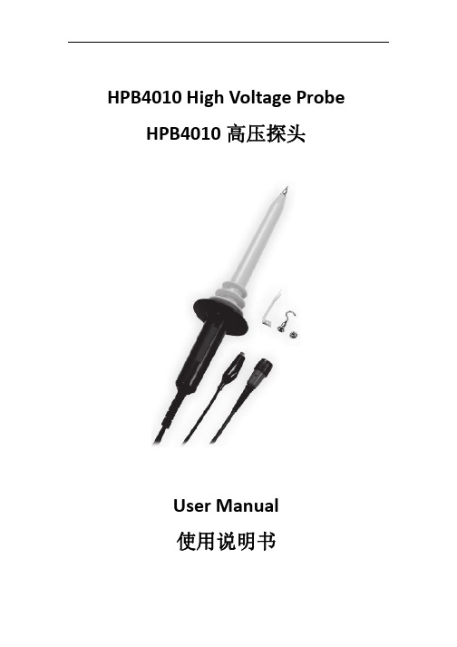
Connect the divider probe common lead(alligator clip) to a good earth ground or reliable ground. Connect the BNC connector to the BNC input of your oscilloscope. Select the desired range of your oscilloscope. Whenever possible, turn the high voltage source off before making any connections. When the measuring voltage are DC 8 KV up, or AC 5KVrms up or AC peak 20KV up, do not exceed 60 second and break off 5 minute at least.
RP1000D系列高压差分探头用户手册

DC 衰减比为 X50:≤ 350Vpp,约 125Vrms 或
DC
衰减比为 X200:≤ 1400Vpp,约 500Vrms
或 DC
最大输入电压
最大差分电压:1400V(DC+AC 峰峰值)或
500Vrms 输入端对地电压:600Vrms
输入阻抗
差分:4MΩ/1.2pF
单端对地:2MΩ/2.3pF
查看所有终端额定值。 为避免起火和过大电压的冲击,请查看产品上所有的额定值和标记说 明,请在连接产品前查阅产品手册以了解额定值的详细信息。
请勿开盖操作。 请勿在仪器机箱打开时运行本产品。
避免电路外露。 电源接通后,请勿接触外露的接头和元件。
怀疑产品出故障时,请勿进行操作。 如果您怀疑本产品出现故障,请联络RIGOL授权的维修人员进行检 测。任何维护、调整或零件更换必须由RIGOL授权的维修人员执行。
RP1000D 系列用户手册
5
RIGOL
规格
技术参数
RP1025D:
带宽
衰减比为 X50 和 X200:DC - 25MHz (-3dB)
衰減比为 X20:DC - 15MHz
衰减比
X20、X50、X200
精度
±2%
输入电压范围(DC 衰减比为 X20:≤ 140Vpp,约 50Vrms 或
+ AC 峰峰值)
例如:示波器的衰减比设置为 1X,高压探头的衰减比设置为 X200,示波器上的垂直档位为 0.5V/div,则实际的垂直档位为 200X0.5V/div=100V/div。当示波器的输入阻抗是 50Ω 时,实际 垂直档位为 2X200X0.5V/div=200V/div。
注意:当示波器的衰减比与高压探头的衰减比设置一致时,示波 器上显示的垂直档位即为实际档位。
泰克 P5122 100X 探头 手册说明书

P5122100X ProbeThe P5122Probe is a high voltage probe with 100X attenuation and a compensation range of 10to 25pF.The probe is designed for use with Tektronix TPS2000and THS3000series floating oscilloscopes with high input impedance (1M Ω).The probe has no user-or Tektronix-serviceableparts.WARNING.The reference contact ring (see below)is always the same voltage as the reference lead.To avoid arc flash,always ensure the insulation sleeve or hook tip is installed to cover the reference contactring.Connecting the Probe to the OscilloscopeConnect the probe as shown in the illustrationsbelow.Compensating the ProbeDue to variations in oscilloscope input characteristics,the low-frequency compensation of the probe may need adjustment after moving the probe from one oscilloscope channel to another.If a 1kHz calibrated square wave displayed at 1ms/division shows signi ficant differences between the leading and trailing edges,perform the following steps to optimize low-frequency compensation:1.Connect the probe to the oscilloscope channel that you plan to use for your measurements.2.Connect the probe to the probe compensation output terminals on the oscilloscope frontpanel.WARNING.To avoid electric shock,only connect to the Probe Comp signal on the oscilloscope when making this adjustment.3.Depress the locking pin inside the protective sleeve.4.Turn the sleeve and the cable end until the adjustment is visible through theopening.5.Push AUTOSET or otherwise adjust your oscilloscope to display a stable waveform.6.Adjust the trimmer in the probe until you see a perfectly flat-top square wave on the display.(Seeillustration.)WARNING.To avoid electric shock,only use the insulated adjustment tool when making compensation adjustments.7.Turn the sleeve back and lock the sleeve inplace.WARNING.To avoid electric shock,ensure that the sleeve is locked in the closed position after making compensation adjustments.Connecting the Probe to the CircuitUse the standard accessories included with the probe to connect to your circuit.(See Table1.)WARNING.To avoid electric shock when using the probe or accessories,keep fingers behind the finger guard of probe body &accessories (as shown).To reduce risk of shock,when using the probe on floating measurements,ensure the reference lead accessories are fully mated before connecting the probe to the circuit under test.Standard AccessoriesThe standard accessories included with the probe can be reordered as a kit.The kit includes one of each item shown below.Order Tektronix part number 020-3046-00.Table 1:Probe accessories kitItemDescription Hook tip 1.Press onto probe tip2.Squeeze the hook tip to extend the conductive hook3.Clamp hook ontoconductor Reference lead,with hook clip 1.Secure lead to probe head ground pin2.Connect hook clip to circuitreferenceReference lead,withmini-alligator clip 1.Secure lead to probe head ground pin2.Squeeze clip and connect to circuitreference CAUTION.This accessory is rated 30VAC maximum.Do not use for MAINS connection.Ground spring for probe tip 1.Press onto probe tip2.Probe circuits with nearby reference testpointsAdjustment tool Use only this insulated tool for compensation adjustmentsP5122200MHz 100X High Voltage Probe Instructions*P071272003*071-2720-03Speci ficationsRead the caution below if you are using the probe with the TPS2000series oscilloscope input set to ACcoupling.CAUTION.When the oscilloscope input is set to AC Coupling,do not probe DC levels >300V or AC signals less than 1Hz and >300V RMS .(See graphbelow.)Refer to the reference lead derating curve below when making floatingmeasurements.Table 2:Electrical and mechanical speci ficationsCharacteristic Speci fication BandwidthDC to 200MHz (–3dB)System attenuation accuracy 100:1Compensation range 10pF–25pF System input resistance 100M ΩSystem input capacitance 4.6pF Maximum tip input voltage1000V CAT IICharacteristic Speci fication Maximum reference lead voltage to ground 600V CAT II Cable length1.2mTable 3:Environmental speci ficationsCharacteristics Description TemperatureMaximum operating Minimum operating Nonoperating +40°C (+104°F)+5°C (+40°F)–55°C to +75°C (–67°F to +167°F)Humidity 80%up to +30°C (+86°F),falling linearly to 50%at +40°C (+104°F)AltitudeOperating Nonoperating2.0km (6,600ft)maximum 15km (50,000ft)maximumTable 4:Certi fications and compliancesCharacteristics Description ECDeclaration ofConformity Compliance was demonstrated to the following speci fication as listed in the Of ficial Journal of the European Communities:Low Voltage Directive 2006/95/EC:EN61010-031:2002Category Examples of Products in this CategoryCAT III Distribution-level mains,fixed installationCAT IILocal-level mains,appliances,portable equipmentMeasurement Category DescriptionsCAT ICircuits not directly connected to mains.Pollution Degree 2Do not operate in environments where cond–uctive pollutants may be present (as de fined in IEC 61010-1).Rated for indoor use only.Additional Safety StandardsUL61010B-1,First Edition &UL61010B-2-031,First Edition.CAN/CSA-C22.2No.1010.1-92,&CAN/CSA-C22.2No.1010.2.031-94IEC61010-031:2002Equipment Recycling.This product complies with the European Union’s requirements according to Directive 2002/96/EC on waste electrical and electronic equipment (WEEE).For more information about recycling options,check the Support/Service section of the Tektronix Web site ().Safety SummaryReview the following safety precautions to avoid injury and prevent damage to this product or any products connected to it.To avoid potential hazards,use this product only as speci fiing the probe or accessories in a manner not speci fied could result in a shock or fire hazard.To Avoid Fire or Personal InjuryFor Use With TPS2000and THS3000Series Oscilloscopes Only.Do not float the reference lead of this probe above the rated float voltage (600V RMS CAT II).Connect and Disconnect Properly.Connect the probe output to the measurement instrument before connecting the probe to the circuit under test.Disconnect the probe input and the probe reference lead from the circuit under test before disconnecting the probe from the measurement instrument.Avoid Electric Shock.To avoid injury or loss of life,do not connect or disconnect probes or test leads while they are connected to a voltage source.Observe All Terminal Ratings.To avoid fire or shock hazard,observe all ratings and markings on the product.Consult the product manual for further ratings information before making connections to the product.Avoid Electric Shock.When using probe accessories,never exceed the lowest rating of the probe or its accessory,whichever is less,including the measurement category and voltage rating.Avoid Electric Overload.To avoid injury or fire hazard,do not apply potential to any input,including the reference inputs,that varies from ground by more than the maximum rating for that input.Avoid Exposed Circuitry and Do not Operate WithoutCovers.Do not touch exposed connections and components when power is present.Inspect The Probe And Accessories.Before each use,inspect probe and accessories for damage (cuts,tears,defects in the probe body,accessories,cable jacket,etc.).Do not use if damaged.Do Not Operate in Wet/Damp Conditions.Do Not Operate in an Explosive Atmosphere.Keep Product Surfaces Clean and Dry.Safety Terms and Symbols Terms in This Manual.These terms may appear in thismanual:WARNING.Warning statements identify conditions or practices that could result in injury or loss oflife.CAUTION.Caution statements identify conditions or practices that could result in damage to this product or other property.Symbols on the Product.These symbols may appear on theproduct:Contacting TektronixWeb site: Phone:1-800-833-9200Address:Tektronix,Inc.Department or name (if known)14200SW Karl Braun Drive P.O.Box 500Beaverton,OR 97077USAEmail:*************************Warranty InformationFor warranty information,go to/warrantyCopyright ©Tektronix,Inc.All rights 。
艾克莱·高压探头和测量仪器说明书
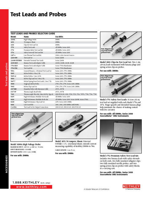
Item shipped may vary from model p ictured here.Model 1600A High Voltage ProbeMAXIMUM INPUT: 40kV DC or 28kV AC, 50/60Hz.INPUT RESISTANCE: 1000M W .DIVISION RATIO: 1000:1 (into 10M W ).For use with: DMMsModel 1651 50 Ampere Shunt:E xternal 0.001W ± 1%, 4-terminal shunt; extends current mea s ur i ng capability of Keithley DMMs to 50A.CABLE LENGTH: 1.4m (56 in).For use with: DMMsItem shipped may vary from model p ictured here.Model 1681 Clip-On Test Lead Set: Two 1.2m (48 in) leads terminated with banana plugs and spring action clip-on probes.For use with: DMMsItem shipped may vary from model p ictured here.Model 1751 Safety Test Leads: 91.4cm (36 in) test lead set supplied with each Model 175A and 197A. Finger guards and shroud e d banana plugs help minimize the chance of making contact with live circuitry.For use with: All DMMs, Series 2400 SourceMeter ®SMU InstrumentsModel 1752 Premium Safety Test Lead Kit:Includes two banana leads with safety shrouds on both ends, two fully insulated alligator clips, two fully insulated needle probes, and two spring-action clip-on probes with safety blocks, in a carrying case.For use with: All DMMs, Series 2400SourceMeter SMU InstrumentsA C C E S S O R I E SItem shipped may vary from model p ictured here.Model 1754 Universal Test Lead Kit: 10-piece test lead kit with interchangeable plug-in acces-sories. Kit includes: 1 set of test leads, 91.4cm (36 in), 1 red and black; 2 spade lugs, 2 standard banana plugs, 2 hooks, and 2 min i a t ure alligator clips with boots.For use with: All DMMs, Series 2400SourceMeter SMU InstrumentsModel 2187-4 Low Thermal Test Lead Kit: Includes an input cable with banana termina-tions, banana extensions, sprung-hook clips, alligator clips, needle probes, and spade lugs to connect the Model 2182A to virtually any DUT. The kit is also used to connect the Model 2182A directly to the Model 622X guard to improve response time for pulsed measure-ments or to reduce errors when measuring high impedance devices.For use with: 2182A, 6220, 6221, 6220/2182A,6221/2182AModel 2600-BAN: 1m (3.3 ft) banana test leads/adapter cable for a single Series 2600B SourceMeter channel (two needed for use with Model 2602B and 2612B). Provides safety banana connections to Hi, Sense Hi, Lo, Sense Lo, and guard.For use with: 2601B, 2602B, 2611B, 2612BModel 2260-008: Test lead set with lugs, 10AWG, 122m (48 in), red/blue wire pair with #10 terminal lugs on each end.For use with: Series 2260BModel 2260B-EXTERM: Extended Terminal Test Leads, 0.7m (28 in.), and terminal box to bring outputs to the front of the instrument or another location. Magnetic base attaches to side of the instrument.For use with: Series 2260BModel 3706-BAN: 1.4m (4.6 ft) banana test leads/adapter cable for Model 3706A mainframe with high performance multimeter option. Provides direct connection to high performance multimeter utilizing rear panel backplane con-nector. Safety banana connections to HI, LO, Sense HI, Sense LO, and AMP.For use with: Series 3700A mainframesModel 3706-TLK Test Lead Kit: Includes 3706-BAN banana test leads/adapter cable and plug-in test lead accessories. Test lead accessories include: 4 spring hook probes, 2 needle test probes, 4 safety plug adapters, and carrying case.For use with: Series 3700A mainframesModel 5804 Test Lead Set: Designed to be used with Keithley instruments that measure 4-terminal resistance. Contains: 2 test leads, 0.9m (36 in), red and black; 2 test clips, red and black; 2 plunger clip adapters, red and black; 2 alligator clips with boots (accept standard test probe tip); 2 alligator clips with boots (barrels accept standard banana plugs).For use with: Series 2400 SourceMeter ® SMUInstruments, 2750, DMMsItem shipped may vary from model p ictured here.T e s t l e a d s a n d p r o b e sModel 5805 Kelvin Probes: 2 spring-loaded test probes, red and black, 0.9m (36 in) with banana plug termination. De s igned to be used with Keithley in s tru m ents that measure 4-terminal re s is t ance and in-circuit current. 1⁄8-in spacing between pin tips. A package of 8 re p lace m ent contacts (P/N CS-551) is available.Model 5805-12: Similar to 5805 but 3.6m (12 ft) in length.For use with: Series 2400 SourceMeter SMUInstruments, 2750, DMMsModel 5806 Kelvin Clip Lead Set: 2 clip test leads, red and black, 0.9m (36 in) with banana plug ter m i n a t ion. Designed to be used with Keithley instruments that meas u re 4-terminal re s is t ance. Maximum jaw opening ½ in. A package of 8 r eplace m ent elastic bands (P/N 5806-306B) is a vailable.For use with: Series 2400 SourceMeter SMUInstruments, 2750, DMMsModel 5807-7 Helical Spring Point Test Leads: Two excellent Kelvin test probes for Keithley in s tru m ents that measure 4-terminal re s is t ance. The probes have point e d tips that rotate when pressure is exerted on the handle. Good contact is assured, and the handle can be held at any angle to the mea s ure m ent surface. The lead wires ter m i n ate in banana plugs. Lead wire length: 2m (7 ft).For use with: Series 2400 SourceMeter SMUInstruments, 2750, DMMsModel 5808 Low Cost, Single Pin, Kelvin Probes: Two 1.17m (46 in) long, single fixed pin probes with source and sense leads per probe and color coded standard safety banana plugs. Designed for applications requiring Kelvin resistance measurements with the convenience of a single point of circuit contact. The Kelvin connection at the base of each probe pin results in very low resistance errors, eliminating all wire and probe body resistance. For the highest pre-cision sensing applications, use the Model 5805, 5806, or 5809 for complete control over sensing point placement.For use with: 2700, 2701, 2750, Series 2400,DMMsModel 5809 Low Cost, Kelvin Clip Lead Set: Two 0.94m (37 in) long probes with alligator style clips, each with opposing blade source and sense connections to color coded standard safety banana plugs. Designed for applications requiring Kelvin connection to wires, axial lead-ed components, and other terminals able to be clipped onto. The miniature blade design accom-modates narrow available width applications as well as general lighter duty applications. The maximum jaw opening is 9.14mm (0.36 in) and the blade width is 2.92mmm (0.115 in).For use with: 2700, 2701, 2750, Series 2400,DMMsModel 6517-RH Humidity Probe: The 6517-RH comes with a 3m (10 ft) extension cable and is designed to be used with the 6517B Electrom-eter. The 6517-RH measures the relative humidity of the testing environment.OPERATING TEMPERATURE RANGE: –10°C to +60°C OPERATING HUMIDITY RANGE: 0 to 100% RH MEASURING RANGE: 10 to 90% RHTEMPERATURE DEPENDENCE: <±2% from –10°C to +60°CFor use with: 6517A and 6517B ElectrometersA C C E S S O R I E SModel 6517-TP Thermocouple Bead Probe: Designed to be used with the 6517B Electro m -eter, the 6517-TP measures the temperature of the testing en v i r on m ent. 6517-TP is 36 in. long and has a temperature calibration (range) of 0°C to 1250°C. Type K thermocouple.For use with: 6517A and 6517B Electrometersand 2110 DMMModel 7401: Type K ther m o c ou p le wire kit includes 30.5m (100 ft) of type K (chromel-alu-mel) ther m o c ou p le wire.For use with: 2001-TCSCAN, 2110, 3720, 3721,3724, 7057A, 7700, 7706, 7708Model 8605 High Per f or m ance Modular Test Leads: Highest quality lead with sili c one insula-tion, and removable test probes. Rated to 1500V. UL listed.LENGTH: 1m (3.3 ft).For use with: All DMMs, Series 2400 SourceMeter ® SMU InstrumentsItem shipped may vary from model p ictured here.Model 8606 High Per f or m ance Modular Probe Kit: For use with Model 8605 High Per-for m ance Modular Test Leads. Contains 2 each spade lugs, alligator clips, and re t ract a ble hooks.For use with: All DMMs; Series 2400 and Series 2600B SourceMeter SMU Instruments;Series 3700AModel 8608 High Per f or m ance Clip Lead Set: High quality clip lead set with removable test clips. NRTL listed. Rated to 1000V CAT 3 and 20 amps.LENGTH: 1.2m (3.9 ft).For use with: 2450, Series 2400 SourceMeterSMU Instruments, Series 3700A DMMsModel 8681 Low Cost RTD: This inexpensive RTD has small size (0.09 in × 0.09 in) and fast thermal response time. 100W , 0.385%/°C ele-ment. Meets or exceeds DIN 43760-1980-A, IEC 751:1983-A, BS1904: 1984-A, and JIS C1604-1981-0.2. Can be used with Model 8680 RTD Input Probe Adapter. Measures from –200° to +600°C.LENGTH: 0.9m (3 ft).ACCURACY: ±(0.15°C + 0.002 × |t|)/°C, where |t| is absolute value of temperature in °C.For use with: 2001, 2002, 2010 DMMs (with 8680), 7700, 7702, 7706, 7708Item shipped may vary from model p ictured here.Model CA-109A Test Lead Set: For output con-nec t ions (two red, two black).For use with: 2000-SCAN, 2001-SCAN, 2001-TCSCANT e s t l e a d s a n d p r o b e s。
RP1018H高压探头用户手册

2. Safety Precautions
Thank you for purchasing RP1018H high voltage probe. High voltage probe can prevent high voltage testers from subjecting to unexpected shocks when doing high voltage measurement work. Before using the high voltage probe, the operator must read and fully understand the safety rules. In addition, this high voltage probe only for the person who are trained, experienced, or otherwise qualified to recognize hazardous situations and who trained in the safety precautions that necessary to avoid possible injury when using such a device.
长地线更换为鳄鱼夹。
当测量 40MHz 以上的高频电压 时,请改用此鳄鱼夹直接接地, 可以获得更佳的频率响应。
5. 注意事项
1) 请勿将测试设备的接地线从地面接线柱上移开。 接地连接是探头安全操作的一个关键点。当高压测量的时候,如果没有这种连接 将可能导致人身伤害或者对连接的示波器、探头产生损害。在探头测试端测试连 接高压前,一定要先连接好地线,并且地线连接不能轻易挪开,直到高压测试端 远离高压源。
炜盛 WPAK63通用型隔离膜压力传感器说明书
通用型隔离膜压力传感器(型号:WPAK63)使用说明书版本号:1.3实施日期:2021-04-08郑州炜盛电子科技有限公司Zhengzhou Winsen Electronic Technology Co., Ltd声明本说明书版权属郑州炜盛电子科技有限公司(以下称本公司)所有,未经书面许可,本手册任何部分不得复制、翻译、存储于数据库或检索系统内,也不可以电子、翻拍、录音等任何手段进行传播。
感谢您使用炜盛科技的系列产品。
为使您更好的使用本公司产品,减少因使用不当造成的产品故障,使用前请务必仔细阅读本说明书并按照所建议的使用方法进行使用。
如果用户不依照本说明书使用或擅自去除、拆解、更换传感器内部组件本,公司不承担榆次造成的任何损失。
您所购买产品的颜色、款式及尺寸以实物为准。
本公司兼承科技进步的理念,不断致力于产品改进和技术创新。
因此,本公司保留任何产品改进而不预先通知的权力。
使用本说明书时,请确认其属于有效版本。
同时,本公司鼓励使用者根据其使用情况,探讨本产品更优化的使用方法。
请妥善保管本说明书,以便在您日后需要时能及时查阅并获得帮助。
郑州炜盛电子科技有限公司WPAK63通用型隔离膜压力传感器产品描述图1:传感器实物图WPAK63系列是采用高精度进口扩散硅压力敏感芯片和成熟的生产工艺封装而成的压力芯体,是制造压力传感器及压力变送器的核心部件,作为一种高性能的压力敏感元件,可以方便地进行放大处理,装配成标准信号输出的变送器。
本司可根据用户的需要,承接特殊定制,如全焊接结构、宽温度补偿、定制外形、高可靠、抗强冲击及抗振动等压力传感器,为客户提供更可靠地解决方案。
特点● Φ19mm 标准OEM 压力芯体,与国内外市场同类型产品互换性强 ● 全不锈钢316L 封装,抗腐蚀 ● 宽温度补偿-10 ~+70℃● 恒流、恒压激励可选 ● 可做归一输出 ● 电路板灌胶防潮保护 应用● 过程控制系统 ● 压力校准仪器 ● 液压系统 ● 生物医药仪器 ● 液压系统及阀门 ● 液位测量 ● 武器装备● 制冷设备和HVAC 控制● 航舶和航海 ● 飞机和航空电子系统等效电路图(1)四线引出(补偿)(2)五线引出(未补偿)技术指标量程范围-100kPa~0~10kPa…100MPa压力类型表压、绝压、密封压激励 1.5mA或10V输入阻抗恒流:2kΩ~5KΩ;恒压:3kΩ~18kΩ电气连接管脚或导线补偿温度0℃~60℃、-10℃~70℃≤35kPa:0℃~60℃,>35kPa:-10℃~70℃工作温度-40℃~120℃储存温度-40℃~125℃绝缘电阻≥200MΩ/250VDC响应时间≤1ms 升至90%FS 测量介质液体和气体机械振动20g(20~5000HZ)冲击100g(10ms)使用寿命10×106(压力循环)结构性能指标膜片材质316L壳体材质316L灌注液体硅油密封圈丁氰或氟橡胶基本参数指标项目条件最小典型最大单位备注非线性-0.3 ±0.25 0.3 %FS 注⑴迟滞-0.05 ±0.03 0.05 %FS重复性-0.05 ±0.03 0.05 %FS零点输出-2 ±1 2 mV满量程输出1.5mA ,10kPa 20mV 1.5mA,其余量程50 90 15010V,10kPa 3010V,其余量程60 100 110零点温漂10kPa -2 ±1.5 2%FS 注⑵其余量程-1.5 ±0.75 1.5灵敏度温漂-1.5 ±0.75 1.5 %FS 注⑵热迟滞-0.075 ±0.05 0.075 %FS 注⑶长期稳定性-0.3 ±0.2 0.3 %FS/年注:⑴采用BFSL最小二乘法。
高压隔离探头使用方法
高压隔离探头使用方法一、引言高压隔离探头是一种常用的电气测试仪器,用于测量高压电源或设备中的电压。
正确使用高压隔离探头对于确保操作安全和测试准确性至关重要。
本文将介绍高压隔离探头的使用方法,包括安装、连接、调整和注意事项。
二、安装1. 确保在使用高压隔离探头之前,已经断开电源,并且待测设备已经完全排除电源。
2. 将高压隔离探头插入测试仪器的输入接口,并确保连接牢固。
3. 将高压隔离探头的输出接口与待测设备的电源或电路连接。
三、连接1. 在连接高压隔离探头之前,确认设备已经处于安全状态,并且没有残余电荷。
2. 将高压隔离探头的输入线缆连接到待测设备的正极,输出线缆连接到待测设备的负极。
3. 确保连接牢固,并且没有松动或损坏的部分。
四、调整1. 在连接完成后,打开测试仪器,并根据仪器的使用说明进行调整。
2. 调整高压隔离探头的灵敏度,以适应不同的测试场景和电压范围。
3. 根据待测设备的电压范围,调整测试仪器的量程和测量模式。
五、注意事项1. 在使用高压隔离探头时,务必佩戴绝缘手套和护目镜,确保自身安全。
2. 避免高压隔离探头与其他金属物体接触,以免引发电弧和短路。
3. 在使用过程中,严禁拆卸、改装或修理高压隔离探头,以免损坏探头或造成电击风险。
4. 高压隔离探头仅用于测量电压,不可用于测量电流或其他参数。
5. 在使用高压隔离探头之前,务必仔细阅读并理解探头的使用说明和安全警示。
六、总结使用高压隔离探头是一项重要的电气测试工作,正确的使用方法可以确保测试的安全和准确性。
本文介绍了高压隔离探头的安装、连接、调整和注意事项,希望能对读者在实际操作中有所帮助。
在使用高压隔离探头时,务必注意安全,遵循使用说明,并定期检查和维护探头的状态,以确保测试的可靠性和准确性。
- 1、下载文档前请自行甄别文档内容的完整性,平台不提供额外的编辑、内容补充、找答案等附加服务。
- 2、"仅部分预览"的文档,不可在线预览部分如存在完整性等问题,可反馈申请退款(可完整预览的文档不适用该条件!)。
- 3、如文档侵犯您的权益,请联系客服反馈,我们会尽快为您处理(人工客服工作时间:9:00-18:30)。
iii
目 录 安全规则...................................................................................................iii 概述 ........................................................................................................... 1 应用领域.................................................................................................... 1 本产品的特点............................................................................................ 2 装箱清单.................................................................................................... 3 普通探头进行强电测试存在的问题 ........................................................ 3 高压差分探头的原理简介 ........................................................................ 4 CIP8108 高压隔离探头的原理简介 ....................................................... 5 探头面板说明............................................................................................ 6 输出 BNC 插头说明 ................................................................................. 7 探头操作步骤............................................................................................ 7 电池仓盖打开方法.................................................................................... 8 探头悬挂方法............................................................................................ 8 区分不同的通道........................................................................................ 9 电气指标.................................................................................................. 10 机械规格.................................................................................................. 13 环境特性.................................................................................................. 13 电源规格.................................................................................................. 13 内置充电器指标...................................................................................... 14 充电注意事项.......................................................................................... 14 保养与维护.............................................................................................. 15 保修条款.................................................................................................. 16
④输入电容低至 0.33pF 约为常见高压差分探头的十分之一,低输入电容使探头对被测电路的 负载效应降至更低,尤其适合现代高频开关功率变换电路的测试。 ⑤1500V 量程,DC~80MHz 带宽 并设有×1000 和×100 两档衰减比,满足主流电力电子设备测试要求。 ⑥数字直流偏移调节 只需通过面板上两个按键,就可随时调节输出直流偏移,方便快捷。 ⑦内置充电器及可充电池 内置快速充电电路,配有高容量镍氢电池,无需反复更换干电池,降 低使用成本。同时也可使用外接电源。
应用领域
■开关电源 ■变频器 ■电子镇流器 ■逆变、UPS 电源 ■焊接、电镀电源 ■感应加热、电磁炉 ■变频家电 ■显示器 以上产品的研发、调试或检修及 ■电工试验 ■低压电器试验 ■电力电子与电力传动实验等
1
CIP8108 高压隔离探头 使用手册
本产品的特点
①真正的电气隔离 其高压输入端与低压输出端之间是真正隔离的,绝缘电阻大于 2000MΩ。 ②更高的安全性 与常规高压差分探头相比,本产品高压输入端与低压输出端之间的安 全屏障增加为两道,其一是输入分压器的高压电阻,其二是隔离电路 中的隔离壁垒。 ③共模抑制比高达 130dB 比常见高压差分探头提高一至二个数量级: DC~50Hz, >130dB 100kHz, 1MHz, >100dB >90dB
iv
CIP8108 高压隔离探头 使用手册
概述
CIP8108 高压隔离探头可以将输入端的高电压信号变换成低电压信 号,并经电气隔离以后,送到输出端。它最高可以测量 1500V 电压,频带 宽度是 DC~80MHz, 衰减比分 1000:1 和 100:1 两档。 它的输入端和输出端 之间完全电气隔离,连接到示波器上后,可以隔离地测量 1500V 以下的电 压波形,不仅提高人身安全性,并且无需再考虑探头对地短路和通道间共 地短路等问题,也无需再使用隔离变压器,使电力电子线路的研究调试变 得非常安全、方便和准确。
3
CIP8108 高压隔离探头 使用手册
若不同通道的探头地线接在了不同电位的电路节点上,就导致此二节点 间短路,可能损坏被测设备,强电流流过示波器地线,也可能损坏示波 器。 ④再进一步地看,如果示波器不接地,虽然无源探头地线鳄鱼夹接在高压 节点也不会对地短路,但是,示波器对地还是有很大的电容,示波器内 部开关电源与电网间也有电容,最终是鳄鱼夹ห้องสมุดไป่ตู้一点对地有很大电容, 把鳄鱼夹接到被测电路的非地节点,就相当于在这一点接了个大电容, 对电路有很大的影响。 综合来看,用普通无源探头进行浮地测量存在安全隐患及造成测量误 差。
高压差分探头的原理简介
为避免出现上述问题,可使用高压差分探头。高压差分探头是由一对 高压阻容分压器构成差分式分压器,再加差分放大器组成。其原理见图 1。 其中高压电阻 R1 电阻值在数 MΩ左右(也有二十几 MΩ的产品),R2值为 数 kΩ。可见高压输入端与输出地之间有了数 MΩ的电阻,这样就避免了 前面所述用普通无源探头可能出现的危险。 从图 1 可见,高压差分探头其高压输入端与低压输出端之间是不隔离 的, 二者间唯一的安全屏障是电阻 R1, 现有的产品中, 其电阻值为数 MΩ, 最多数十 MΩ。
CIP8108 高压隔离探头
使用手册
产品名称:高压隔离探头 产品型号:CIP8108 文档版本:1.03 编写日期:2007-9-6
杭州祺来电子有限公司
Hangzhou Cheele Electronics Co.,Ltd. 地址:杭州市滨江区南环路 4028 号 邮编:310053 网址: 电话:0571-86691142 传真:0571-86691143
i
◆ 声明
Copyright ©2007 杭州祺来电子有限公司, 版权所有,保留所有权利
由于产品升级或其他原因, 本手册内容会不定期更新, 恕不另行通知。 除非另有约定,本手册仅作为使用指导。本手册中的所有陈述、信息和建 议不构成任何明示或暗示的担保。
ii
安全规则
使用前请务必仔细阅读和遵守以下安全规则,以防人身触电或设备损 坏。若未能按照有关说明使用本产品,可能消弱或失去安全性能。 ■每次使用前请检查高压输入线和测试钩(或测试夹、测试笔)是否有破 损,若有绝缘破损、导体裸露的现象,不可再使用,请即寄回原厂维修。 ■应预先估计被测电压幅值,不可用本产品来测量差模电压大于 1500V, 对地电压大于 1400V 的电压。 ■与本产品连接的示波器(或其他测试设备)应接地。 ■开始测试时,先将本产品的低压输出端与示波器(或其他测试设备)连 接,再将高压输入端与被测点连接;结束测试后,先将本产品的高压输 入端与被测点断开,再将低压输出端与示波器(或其他测试设备)断开。 ■被测设备加电后,不可接触可能带有危险电压的导体部分。 ■若怀疑本产品有故障,不可再勉强使用,请即寄回原厂检测。 ■请保持本产品表面清洁与干燥。 ■不要在高温、高湿、易燃、易爆和强电磁场环境中存放或使用本产品。 ■不可对碱性电池充电,可能导致起火或爆炸。 ■仅使用原配的外接电源适配器。 ■自行拆机可致安全性能下降或失效,不可自行拆机,维修或校准请寄回 原厂。