电动感应玻璃门方案说明
电子感应门施工方案

电子感应门施工方案标准化管理处编码[BBX968T-XBB8968-NNJ668-MM9N]1、安装金属机匣横梁时,请注意使之保持水平,误差为1mm,如不水平会导致门体行走时出现力道不均匀的现象,造成机器寿命降低。
2、门体吊挂的安装:·用附带的门体吊挂螺栓组件把吊架装置安装到门体上指定位置。
安装时应使吊架装置的滑轮中心与门体处于平行状态,如不平行,会缩短滑轮的寿命。
把吊挂装置的滑轮挂到动力梁上。
安装时请勿碰伤动力梁内其他部件及导轨,否则会造成部件故障或滑轮寿命、噪音、异常声音等。
3、限位装置安装:·拧松限位器的安装螺栓。
·把限位器装置确定嵌入到动力梁的导轨上。
首先移动门体确定门体的开闭位置,然后确定限位器的位置。
设定限位器装置的位置时,应使吊挂装置碰到限位器的胶垫后停止。
用六角扳手确实拧紧固定安装螺栓。
4、门体的高度及缝隙调整:拧松固定吊架用螺母,进行调整螺栓的安全调整,拧紧固定吊架用螺母。
确认行走时的阻力。
确认门移动是没有滞重现象,而且没有摩擦声音,如果有问题请确认以下事项:吊挂是否垂直固定在门体上吊挂装置是否与动力梁有摩擦门体与门框之间是否有摩擦门体动扇与地面高度一般保持在10mm。
动扇与定扇之间缝隙为5mm。
5、皮带张力的调整:将张紧轮装置向左用力拉,使皮带保持绷紧,然后拧紧四个压板螺栓。
拧松四个调节固定螺栓·沿顺时针方向旋转张力调整螺栓,调整皮带张力。
·拧紧四个调节板固定螺栓6、地轮的安装,在安装时地轮的中心位置根据门体动扇宽度的一半加上5mm。
(前提为动扇底部内有滑道的,如果没有滑道直接是包饰板的应考虑其在内部的空间距离,根据实际来计算)安装后请确保门体上下缝隙相同,以免时间长损坏地轮。
7、控制系统的调整:(在正常情况下不用去调整,保持出厂设定为好)调整前请用手推动门体动扇数次以保证门体可以平滑的开关。
设定左右切换开关,根据门的开门方向,设定左或右。
AUR°EL HCS-Keeloq 无线磁电子门窗传感器说明书

User ManualLe caratteristiche tecniche possono subire variazioni senza preavviso. La AUR°EL S.p.A non si assume la responsabilità di danni causati dall’uso improprio del dispositivo.WIRELESS MAGNETIC CONTACTThe magnetic contact wireless MAG HCS is a sensor able to detect opening or closing doors or windowsand transmits via radio a alarm signal. It is composed of two distinct elements: a case containing the magnetic contact and electronic card normally placed on the frame of the fixture and a small permanent magnet to fit on the mobile element of the fixture. The working is based on the closing and opening of a sensor capable to operate within a 10-15mm radius from the permanent magnet.MAG HCS is battery power by (CR2032) supplied and designed to ensure autonomy of 2-3 years, it is always internallycontrolled by a meter charge that forwards via radio the battery life time and warns by a beeper and LED, the alarm of discharged battery.It’s available a double auxiliary block terminal independent from internal magnetic contact, where it’spossible to connect a second sensor, eg further magnetic contact, sensor for rolling shutters or other type of sensor that uses a free NC contact. Internal electrical card manages this independent contact and the event of case opening and consequent sends a unique radio code.Other functionalities are: the tamper, which is activated in the event of tampering of the enclosure, the tear can be activated by removing of the sensor installed, a software periodic supervision that communicates via radio the battery status, tamper, magnetic contact independent alarm condition. The radio protocol is a rolling code type, and unique code programmed in AUREL for each sensor. A LED shows radio transmissions, alarms and test.Fig.1 – Sensor and magnetFig. 2 – PCB sensor side1) Sensor2) Permanent Magnet3) Dip switch: not assembled in HCS version4) Jumper 1-4: Setting mode (see "Sensor Configuration). 5) Reed:select magnetic contact with open JP36) Reed: select magnetic contact with closed JP37) Tamper: tamper switch8) Aux In:AUX INPUT9) Battery:batteria mod. CR2032 tipo Litio10) Buzzer:Low battery indicator11) LED:light signals (see signaling) 12) Antenna:please do not modify it* HCS and Keeloq are brand Microchip3JP1 JP2JP3 JP4 6 5127 8124User ManualLe caratteristiche tecniche possono subire variazioni senza preavviso. La AUR°EL S.p.A non si assume la responsabilità di danni causati dall’uso improprio del dispositivo.Fig. 3 – battery PCB sideSensor configurationJumpers allows to setup different operation mode and tests. Do not activate at the same time jumper JP1 and JP2, if you activate jumper JP1, be sure JP2 is not active! After 10 minutes from last jumper status change, sensor configuration mode is off, in order to reset this configuration, take off the battery and insert back after tamper button will press.JP1 Radio Mode JP2 SupervisionJP3 Magnetic contac selection JP4 Magnet settingTab.1 – sensor config.RADIO MODE: allows to verifythe radio link between sensor and receiver. It’s activate once JP1 is closed. Radio transmission works for 30 seconds, then switch on normal works.SUPERVISION FUNCTION : It sends to the receiver side a signal to give a feedback of the status battery and the status of the magnetic, tamper , tear contacts.It’s activated from the closing of JP2 contact, it’s foreseen a transmission each 60 seconds independent from the alarm signal.CALIBRATION OF MAGNETIC SENSOR: It’s a function used during learning procedure of the sensor that helps the installer to place the permanent magnet near the magnetic contact.It is triggered by the closure of JP4 the LED switches on when the magnet closes the magnetic contact and switches off when the contact opens. No radio transmission is activated.After 5 minutes from the starting of the procedure, the sensor will come back to the normal function. To start again the function, disconnect and fit again JP4.MAGNETICCONTACTSELECTION: allows to select, if both are present, one magnetic contact REED depending from the assembly. Selection is made by JP3 if closed, active contact is the one fitted on the large PCB side, if open is the one fitted on the short PCB side.JP3 closed Reed active on large PCB side JP3 open Reed active on short PCB side1012911User Manual MAIN WORKING:Normally is activated after the fitting of the battery or when “RADIO MODE” AND “CALIBRATION OF MAGNETIC SENSOR” functions are finished. The sensor sends the status code when there is a variation of the operation, eg opening or closing of any contact (see "SPECIFICATIONS OF THE RADIO CODE). The led switches on for 100 ms to show the transmission. The time transmission is about 1 sec.Acoustic and luminous signal.are present 1 buzzer and 1 red LED with the following functions:BUZZER: Used to signal low battery and it’s activated when the battery voltage drops below 2.35 volts with a duration time of 2-3 seconds.LED is activated for each radio transmissions (alarm, supervisory radio test). If the case of low battery (below 2.35 V), it blinks quickly for 2 seconds every 5 minutes. The calibration function of the magnetic sensor remains on when the magnetic contact is closed.Technical featuresMin Tipico Max UnitàPower supply (1) 2.1 3 3.3 VCurrent consumption Tx 12 15 mACurrent consumption stand-by 4.0 5.0 6.5 uALow battery 2.1 2.25 2.35 VoltBattery life 2 (1) 3 yearsRadio transmissionStandard frequency OOK modulation433.82 433.92 434.02 MHzModulation OOK On-Off KeyingEffected Radiated Power (E.R.P) 0.5 1.0 mWERP second harmonic < 1GHz -36 dBmERP third harmonic > 1GHz -30 dBmElectromagnetic immunity10 V/mCodifica KeeloqSerial code 28 bitHopping code 32 bitHopping combos 2³² -Working temperature-10 +55 °CCase Dimension 70,4 x 33,6 x 17,4 mm(1) Tipo Litio 3V CR2032Radio code featuresMAG 4MHCS implements the Microchip's Keeloq rolling code with Aurel manufacturer code, customizable on request. The parameters of the protocol Microchip Keeloq are not disclosed and are available on request. The radio transmitted codes related to different functions of MAG HCS are described below. Consider that the S0-S1-S2-S3 codes refer to the 4-bit encoding used by Keeloq (see the documentation about the Microchip Keeloq):Le caratteristiche tecniche possono subire variazioni senza preavviso. La AUR°EL S.p.A non si assume la responsabilità di danni causati dall’uso improprio del dispositivo.User ManualLe caratteristiche tecniche possono subire variazioni senza preavviso. La AUR°EL S.p.A non si assume la responsabilità di danni causati dall’uso improprio del dispositivo.MAGNETIC CONTACT: represented by S3 bit and it has high logic level when the contact is opened or low logic level when the contact is closed.TEAR AND TAMPER CONTACT: they use the same bit S2 and it goes high when one of the two contacts is open. S2 goes low when both are closed.AUXILIARY INPUT: represented by S0 bit and it goes high when the contact is open and low when it’s closed.RADIO MODE: all bits (S0-S1-S2-S3)are at “zero” logic level and this function is used for test radio transmission or learning the radio code in the central unit.SUPERVISION: represented by S1 bit it has high logic level once radio code Supervision is emittedFig.4 –Back frameFig.5 – Back sensorInstallation:1)Place the back frame (fig. 4)on the fixture making sure to turn the magnetic sensor tothe moving part of the frame where the permanent magnet is placed. Then mark the holes printed on thebottom box (see fig. 3), 5-6 mm drill with drill and secure the bottom2)Place the permanent magnet on the mobile part of the fixture trying to match the reference marksin thecase of the sensor and permanent magnet. If the magnet is sufficiently close to the magnetic contact, LEDwill switch on indicating the closure of the magnetic contact. However, the sensor will not be installed at a distance greater than 30mm from the permanent magnet.Fixingholes hookshooksUser Manual Learning procedure and radio test:Prepare the receiver side in the learning mode.Activate the "radio mode" of the MAG 4MHCS by closing JP1 and JP2. The radio will operate for about 30 seconds.Note: The installation of MAG HCS on metal frames can cause radio performance losses. In this case it is advisable to install the magnetic sensor away from screening components and connect an external magnetic contact to the auxiliary inputInstallation with connection to the auxiliary input.Il MAG HCS implement intermally a NO contact, usable from a another sensor The figure above shows a typical application of sensors connected in series to help protect a single device with multiple windows. The various contacts must be connected in series, the opening of one of them will cause the alarm. This scheme will not allow the state opening of each frame.This contact can also be used with any other type of sensor that has a dry contact output NO / NC.Fig.7 – Principio di utilizzo e collegamento del contatto ausiliario del sensore magneticoBattery substitutionThe substitution of the battery must be carried out when the sensor transmits the low battery alarm by radio signal or led or buzzer. However the battery is not completely discharged and will ensure a couple of weeks of working.To substitute, procede as follow:remove the top side of the case, replace the 3V mod. CR2032 litium battery being careful to the polarity, see picture number 8. To obtain a higher time life, five years life time batteries are advised. The accidental reversal of polarity of the batteries does not cause the breaking of the circuit and discharging them. In the case of loosing of substances , remove it taking care to not get in contact with them. Throw used batteries in respect of the normative. See the section 'Information for users'.Le caratteristiche tecniche possono subire variazioni senza preavviso. La AUR°EL S.p.A non si assume la responsabilità di danni causati dall’uso improprio del dispositivo.User ManualLe caratteristiche tecniche possono subire variazioni senza preavviso. La AUR°EL S.p.A non si assume la responsabilità di danni causati dall’uso improprio del dispositivo.Fig. 8 – battery substitutionINFORMATION FOR THE CUSTOMERThe product you purchased, must be separately throw and it can not be thrown as municipal waste, as required by Directive 2002/96/EC. Therefore, this system and all its components, subsystems andconsumables materials that are part of the product, when you take the decision to discard them, must be thrown to collection centers for proper treatment of waste, according as provided by law. To know where these centers are located, you should ask at the municipal offices.CE DECLARATION OF CONFORMITYThe magnetic contact MAG 4MHCS is under the follow normative: ETSI EN 301 489-3 V1.4.1 – Electromagnetic compatibility ETSI EN 300 220-1 V2.3.1 – Radio features EN 60950 – Other featuresCE ReferenceIn the back of the plastic case that encloses the transmitter is present a label with the identification of the module as those reported here at the left side [product name, manufacturer, voltage supply and currentsupply].+ on the top- on the backPull the battery。
自动感应玻璃门原理

自动感应玻璃门原理
自动感应玻璃门是一种能够自动感知人体接近并启动开启机制的门。
它通常使用红外线(IR)传感器技术来检测人体热量和移动,从而触发门的打开机制。
这种感应门系统通常由几个主要组件组成,包括红外线传感器、电源、门控制器和电动门机。
红外线传感器位于门的一侧,通常通过红外线辐射和反射来检测人体的存在。
当有人朝门靠近时,传感器会接收到被人体反射的红外线信号,从而触发门控制器。
门控制器负责接收传感器的信号并控制电动门机的运动,以便打开或关闭门。
传感器通常会设置一个可调节的探测范围,以适应不同宽度的门通道。
当有人接近门时,传感器会检测到人体的热量和移动,并将该信息传输给门控制器。
门控制器根据接收到的信号来判断门是否应该打开或关闭,并相应地控制电动门机的运动。
除了红外线传感器,一些自动感应玻璃门还可以使用其他类型的传感器,如微波传感器或雷达传感器,以实现类似的自动感应功能。
这些传感器通过发射微波或雷达信号,并根据信号的反射来检测人体的存在。
总的来说,自动感应玻璃门利用红外线或其他传感器技术来感知人体接近,并通过门控制器控制电动门的运动,实现自动打开或关闭门的功能。
这种技术在许多公共场所和建筑中被广泛应用,提高了门的使用便捷性和安全性。
玻璃门智能锁使用手册

玻璃门智能锁使用手册使用前请仔细阅读说明书,并妥善保管第一章.产品简介1.外观介绍主锁前副锁前副锁后主锁后正面副锁背面2技术参数第二章.功能简介1.触摸按键触摸按键可以快速连续滑动,按键同时按键灯熄灭,按键自带九宫格输入法,新增用户时可输入中文或英文。
2.感应卡在刷卡区域1cm处刷卡,可支持MF1、身份证、银行卡、CPU卡等。
3.指纹注意事项:指纹采集窗灯亮时,请按上述正确方法将手指放在指纹采集窗上,约1秒钟左右门锁即自动完成指纹采集4.功能概要14电量显示具有电量显示功能,显示当前状态电量值。
15虚位密码开锁密码可随意输入30位以内包含有正确的密码即可开门;有效防止他人旁观窃取密码。
16应急开门电池电压不足驱动电机时,可用外接电源供电应急开门或者机械钥匙应急开门。
17双电源供电支持两路电源同时供电。
18演示模式供展会、展示演示使用,任何指纹都可以开锁。
第三章.操作说明进入“主菜单栏”方式:触摸面板数字键至系统上电,直接输入“0#管理密码或管理指纹#”进入主菜单栏界面,管理密码默认“0123456789”,如果密码忘记,可以按一下设置按键恢复管理员密码。
1.菜单导航■管理员密匙设定进入主菜单栏界面,按“#”键进入“用户管理”,选择“管理员”,按“#”键确认进入,选择“编辑密码”、“编辑指纹”或“编辑卡”,按“#”键确认,再根据屏幕提示“请配置密码”、“请配置指纹”或“请配置卡”,按“#”键确认,按“*”键退出菜单,如果想输入多个管理密匙,重复以上操作即可;管理员具备最高权限,,不能对管理员进行删除,但是可以对管理员的指纹和卡进行更改或者删除,管理密码只有1组,不能删除,新增密码自动覆盖原密码。
■删除管理密钥进入主菜单界面,按“#”键进入“用户管理”,选择“管理员”,按“#”键确认,选择“编辑密码”、“编辑指纹”或“编辑卡”,按“#”键进入,选择已设置的密钥,按“#”确认,系统提示“是否删除当前指纹”或“是否删除当前卡”,按“3”键确认,按“*”键返回菜单,如果想继续想删除多个密钥,重复以上操作即可,管理密码只有1组,不能删除。
电动门使用说明书
电动门使用说明书欢迎购买我们的电动门产品!为了保证您能够正确、安全地使用产品,特为您提供了以下使用说明。
请您仔细阅读,并按照说明进行正确操作。
1. 产品概述本产品是一款电动门,适用于各种场所的出入口控制。
通过电动机驱动,实现门体的自动打开与关闭,提供便捷的出入通道。
2. 安全须知在使用本产品时,请务必遵守以下安全须知,以避免发生意外事故:1) 请勿让儿童在无成人看护的情况下接近电动门。
2) 请勿站在电动门的活动范围内,以免造成门体碰撞伤害。
3) 请勿进行未经授权的拆卸、改装等行为,以免影响产品的正常运行。
4) 请确保电源接线正常,避免接地不良或漏电导致的安全隐患。
3. 基本操作本电动门采用简单易用的操作方式,具体操作如下:1) 手动模式:当电源故障或其他特殊情况下,可将电动门设定为手动模式,手动推拉门体实现开关控制。
2) 自动模式:正常情况下,将电动门设定为自动模式,门体将按照设定的参数进行自动开关。
4. 参数设置本电动门支持多项参数设置,以满足不同使用需求。
以下为几个常用参数的设置方法:1) 开关速度:可通过控制器上的设定按键,选择不同的开关速度。
2) 延时关闭:可设置电动门在感应到通过人员后,延时一段时间后自动关闭门体。
3) 防夹功能:通过光电开关等装置,实现感应到门体前方有障碍物时,立即停止门体活动,避免夹人。
5. 维护保养为了确保电动门的正常运行和延长使用寿命,请定期进行以下维护保养工作:1) 清洁门体表面,避免积尘影响电动门的正常运行。
2) 检查电源线路和接线端子,确保连接良好,避免线路故障。
3) 定期检查各个零部件的紧固情况,如有松动请及时拧紧。
6. 故障排除在使用过程中,如果发生以下故障,请先排除故障再进行下一步操作:1) 电动门无法开启或关闭:请检查电源线路是否接通,是否存在断电等问题。
2) 电动门运行缓慢或不平稳:请检查电动门是否受到阻碍,是否需要进行润滑保养。
3) 传感器故障:请检查传感器是否受到遮挡,是否需要调整位置。
玻璃工程自动门设计方案

玻璃工程自动门设计方案一、引言自动门是现代建筑中常见的装饰和设施,它不仅美化了建筑外观,还提高了建筑的安全性和便利性。
作为一种高级感和现代感比较浓的自动门,玻璃工程自动门是目前市场上非常受欢迎的自动门类型。
因为玻璃工程自动门的挑选,需要根据实际场地情况进行综合考虑和合理设计,本文将对玻璃工程自动门的设计方案进行详细的介绍。
二、玻璃工程自动门的特点1. 美观性:玻璃材质具有透明性、光洁亮丽等特点,可以为建筑增添现代感和时尚感。
而玻璃工程自动门的设计类型多样,可以根据建筑的整体氛围来选择不同的设计方案。
2. 安全性:使用玻璃材质制作的自动门需要具备一定的安全性和抗风压性,以确保在突发情况下能够及时关闭和避免事故发生。
3. 舒适性:自动门的开启和关闭需要对温度和湿度有一定的适应性,避免在不利天气条件下自动门的使用产生影响。
4. 防水防尘性:自动门需要保持干净的表面,因此具备防尘和防水的特性对于玻璃工程自动门来说是必不可少的。
5. 耐用性:作为建筑的门类设施,自动门需要经受住时间和使用的考验,因此具备一定的耐用性是其设计方案的一个重要考虑点。
三、玻璃工程自动门的设计方案1. 材料选择玻璃工程自动门的设计中,玻璃的选材十分重要。
一般情况下,需要选择具有较高透光性和强度的玻璃作为自动门的材料,以保证门体的美观和安全。
在材料选择上,可以考虑使用钢化玻璃、夹胶玻璃或夹丝玻璃等材质,这些材料具有较高的抗风压性和耐用性,适合于户外环境的自动门设计。
2. 结构设计玻璃工程自动门的结构设计需要考虑门体的整体稳定性和操作灵活性。
一般情况下,需要考虑门体的开启方式、传动装置、门体的轨道和门扇等方面的设计。
在结构设计上,可以选择单扇门、双扇门、滑动门或折叠门等不同类型的自动门,根据建筑的空间和使用需求来选取合适的门体结构。
同时,传动装置的选取也需要与门体结构相匹配,以确保门体开启和关闭的平稳和安全。
3. 功能设计玻璃工程自动门的功能设计需要考虑门体的开启和关闭方式、人员感应功能、防夹手功能、安全灯光和声音提示等方面。
电动门工程方案设计
电动门工程方案设计1. 项目背景随着科技的不断发展,电动门作为一种便捷、安全、高效的门禁设备,已经被广泛应用到商业、工业、医疗、住宅等场所。
本方案针对一家办公楼的电动门工程进行设计,旨在提升办公楼的门禁安全性、便捷性与美观性。
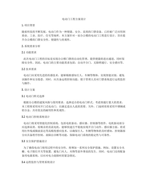
2. 系统需求分析2.1 功能需求此次电动门工程的目标是实现办公楼门禁的自动化管理,提供便捷的进出通道,同时保障安全性。
因此,电动门的主要功能需求包括:自动开合门、无障碍通行、安全感应等。
2.2 技术需求电动门应采用先进的传感技术,能够精准感知行人、车辆等物体,实现智能识别,避免误操作和安全隐患。
同时,应具备远程控制功能,便于管理人员对门禁系统进行远程监控与操作。
3. 设计方案3.1 电动门样式选择根据办公楼的建筑风格与使用要求,选择适合的电动门样式。
考虑到通行量大的需求,本工程将采用双开门式电动门,以满足进出人流的需要。
另外,门扇材质将采用不锈钢或铝合金,具有优良的耐用性和美观性。
3.2 电动门控制系统设计电动门将采用智能化控制系统,包括电机驱动、感应器、控制器等组件。
电机驱动部分应选择高效、低噪音的直流电机,能够快速且平稳地实现开合门动作。
感应器方面,将采用红外线或微波雷达等高精度感应技术,以确保行人、车辆等物体的及时感知。
控制器部分应具备程序控制、故障自诊断等功能,保障电动门系统的稳定性与可靠性。
3.3 安全保护措施设计为了确保电动门使用过程中的安全性,将增加一系列安全保护措施。
例如,设置安全光栅、电子限位开关等装置,避免门夹人、夹物等意外事故的发生。
同时,电动门还将配备备用电源系统,以应对电力故障时的紧急情况。
3.4 远程监控与管理系统设计为了方便管理人员对电动门的远程监控与管理,将引入远程监控系统。
该系统能够通过网络远程实时监控电动门的状态、故障信息等,并可以进行远程操作,实现对门禁系统的智能化管理。
4. 工程实施方案4.1 施工准备在开始施工之前,首先进行现场勘测与测量,准确掌握电动门安装位置、尺寸以及周围环境情况。
感应门说明书

篇一:感应门使用说明感应门使用说明1. 人员以正常速度从门外或门内走向自动门,自动门应该自动打开,自动门的动作应该平滑而且没有出现碰撞的情况;自动门打开后,人员以每秒约 150mm -200mm 的速度慢速通过自动门时,自动门应该保持打开状态;2. 当人员离开自动门感应器感应区后,在延时 1-10 秒后(时间长短可以由自动门开关参数来设置),自动门将自动关闭,自动门的动作应该平滑而且没有出现碰撞的情况;3. 观察人员正常通过自动门的行走路线,需要把日常行走路线调整为人员正对走向自动门,而不是以一定的角度走向自动门;4. 走向自动门时,自动门感应器的感应宽度范围应该大于门完全打开的宽度;5. 如果自动门安装了辅助光线传感器(红外对射保护装置),当门打开时,人站着不动,用手遮挡辅助光线传感器,门应该保持打开状态。
当手离开后几秒内,门应该重新关闭。
6. 不可以在温度过高(50度以上)、过低(-20度以上)、潮湿、多灰尘环境下使用。
7. 门在自动感应状态下使用时不可以摆放一些活动(或者风吹动会活动)的东西在门的感应头检测的范围内,这会容易造成自动门的误运动动作发生8. 不可以经常性在手掰动自动感应门,这会减低自动感应门的使用寿命。
【注意事项】1、保障自动门安全、可靠地运行,用户或自动门管理人员在日常需要对自动门进行必要的运行检查。
[ 测试检查需要在没有其他人员干扰的情况下进行 ]2、自动门出现故障时,请立即切断自动门电源,然后联系自动门经销商处理篇二:自动门设计说明书机电工程学院课程设计说明设计题目: 自动门控制系统设计学生姓名:解泓立学号: 200848050315 专业班级:机制f0908 指导教师:王宗才2011年 12 月 08 日书内容摘要在当今社会自动门的应用也越来越广泛。
它现在为许多宾馆、超市、百货大楼等现代建筑所使用,不仅可以美化出入口环境,而且具有节能、防尘、隔音等功能,同时也是建筑物智能化的重要指标。
- 1、下载文档前请自行甄别文档内容的完整性,平台不提供额外的编辑、内容补充、找答案等附加服务。
- 2、"仅部分预览"的文档,不可在线预览部分如存在完整性等问题,可反馈申请退款(可完整预览的文档不适用该条件!)。
- 3、如文档侵犯您的权益,请联系客服反馈,我们会尽快为您处理(人工客服工作时间:9:00-18:30)。
电动感应玻璃门方案说明
1、主控制器:它是自动门的指挥核心,通过内部编有指令程序的大规模集成块,发出相应指令,指挥马达或电锁类系统工作;同时人们通过主控器调节门扇开启速度、开启幅度等参数。
2、感应探测器:负责采集外部信号,如同人们的眼睛,当有移动的物体进入它的工作范围时,它就给主控制器一个脉冲信号;动力马达:提供开门与关门的主动力,控制门扇加速与减速运行。
3、门扇行进轨道:就象火车的铁轨,约束门扇的吊具走轮系统,使其按特定方向行进、滑动。
门扇吊具走轮系统:用于吊挂活动门扇,同时在动力牵引下带动门扇运行。
轨道图
4、步皮带(或三角皮带):用于传输马达所产动力,牵引门扇吊具走轮系统。
下部导向系统:是门扇下部的导向与定位装置,防止门扇在运行时出现前后门体摆动。
电动感应门安装:
原理图
上下门轴必须在一个垂线上,玻璃门必须采用钢结构的横梁做骨架,上轴必须焊接在横梁上,因为上门轴是整个玻璃门的支撑点,必须要牢固,禁止采用上部横梁采用细木板木龙骨结构,因为上门轴与木制作结构连接点只能使用自攻螺丝固定连接,由于开门次数多,时间长了使上门轴容易脱落,造成危险。
预埋地弹簧时要在原地面剔凿一个长方形方坑,四周要大于地弹簧底座的10毫米,用于塞实高标号水泥砂浆,起到牢固的作用,建议地弹簧水泥凝固48h后按照玻璃门,安装好玻璃门地边要距地8-12毫米,预防玻璃门在下垂的时候摩擦地面。
地弹门的上下门轴要座于门框的核心,使玻璃门安装好以后也能座于
门框的核心,起到美观的效果。
安装好玻璃上门边要距横梁3-6毫米,预防门下垂时上门轴和门夹的连接件不至于脱离,还有一个细节问题要注意,门轴与门夹的部位要注入黄油,可以减少连接件的磨损,以延长使用寿命。
成品。