照明控制器调试说明
中川ZC-C-B应急照明控制器使用简易教程
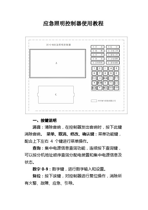
应急照明控制器使用教程一、按键说明消音:清除音响,在控制器发出音响时,按下此键消除音响。
菜单、取消、修改、确认键:菜单功能键,配合上下左右4 个键进行菜单操作。
查询:集中电源信息查询功能,连续按下查询键,可以按分机地址顺序查询分配电装置和集中电源信息及状态。
数字0-9:数字键,进行数字输入和设置。
复位:按下该键,对控制器进行复位操作,消除所有火警、故障、应急、引导。
应急启:按下此键,强制使所有灯具进入应急状态,直至电池放电终止。
(警告:无特殊情况,禁止按应急启)应急停:按下此键,取消灯具强制应急。
二、操作密码:119三、操作控制器收到火警或故障信号后,自动进入火警和故障界面,可直接按“菜单”键,操作其它功能。
按下“复位”键,输入密码“119”后,控制器可复位。
如果控制器同时存在“灯具引导或应急启动、收到火灾报警控制器的火警信息、当前存在故障”的情况,可操作“菜单”键,然后操作查询功能,进入相应的灯具信息显示菜单、火警信息显示菜单、故障信息显示菜单进行查询。
按下菜单键,进入主菜单。
主菜单界面如下:按下相应数字,进入子菜单。
1、设置选项在主界面下,按“2”进入此功能,可显示如下菜单,通过选择相应数字进入功能。
按1.日期和时钟:用于调整控制器时钟,依次输入年、月、日、时、分、秒后,控制器的时钟将改为设定值。
按8.设置打印机:设置打印机工作方式,向上键为允许打印,向下键为禁止打印。
2、查询选项在主界面下,按“3”进入此功能,可显示如下菜单,通过选择相应数字进入功能。
按2.历史记录:用于显示本机自动存储的历史记录,可通过“↑”、“↓”翻页查询。
按“取消”键退至上一级菜单。
按3.当前故障:用于在灯具引导或有火警信息的情况下查询当前故障,可通过“↑”、“↓”翻页查询。
按“取消”键退至上一级菜单。
按4.当前火警:用于在灯具引导的情况下查询当前火警,可通过“↑”、“↓”翻页查询。
按“取消”键退至上一级菜单。
3、测试选项在主界面下,按“4”进入此功能,可显示如下菜单,通过选择相应数字进入功能。
动力照明调试报告模板

动力照明调试报告模板1. 调试日期2019 年 8 月 12 日2. 调试人员•调试负责人:张三•调试人员:李四、王五3. 调试区域本次调试区域为公司楼内 4 层及以下区域,共计 6 个区域。
4. 调试设备本次调试使用的设备如下:•动力照明控制器:型号 DL-658•电源供应器:型号 PS-200•灯具:30 台吸顶灯5. 调试目的本次调试的主要目的是检查 6 个区域的动力照明设备是否正常工作,如发现问题应及时解决。
同时,我们也要确保所有的设备都符合相关的安全标准,保证人员安全。
6. 调试过程6.1 前置工作在正式进行调试之前,我们需要做一些前置工作。
首先是检查所有设备是否到位,所有接线是否牢固。
其次,我们需要连接电源,并打开控制器,同时确保电源连接符合要求,以免引起电路故障。
6.2 调试步骤6.2.1 检查控制器我们首先检查了控制器是否正常工作。
在控制器面板上,我们检查了各个指示灯是否点亮,并检查了控制器是否能够正确控制灯具开关。
在此过程中,我们发现了一些指示灯未点亮,但经过检查后,发现是由于传感器未正确安装导致的。
6.2.2 检查电源供应器接着我们检查了电源供应器是否正常,并检查了电源是否能够满足灯具的功率需求。
在这个过程中,我们注意到一些电源接头不够紧,我们进行了调整以确保良好的接触。
6.2.3 检查灯具最后,我们检查了灯具是否可以正常工作。
我们检查了所有的灯具并确保它们都属于同一型号,以免产生安装问题。
同时,我们检查了灯具的位置和角度是否正确,以确保整个区域可以充分照明。
7. 调试结果通过本次调试,我们发现了一些控制器和电源的接线存在问题,并进行了及时修复。
最终,我们成功地完成了对所有 6 个区域动力照明设备的检查,并调试完成。
在整个过程中,我们保证了人员的安全,同时通过检查和修复问题,也确保了灯具的正常工作。
dmx512灯光控制器说明书

dmx512灯光控制器说明书【一、DMX512灯光控制器简介】DMX512灯光控制器是一种数字通信协议,用于控制舞台灯光、建筑照明等灯光设备。
它通过一根五芯电缆传输数据,实现灯光设备之间的通信与控制。
DMX512协议具有高速、稳定、可扩展性强等特点,成为灯光控制领域的主流标准。
【二、DMX512灯光控制器主要功能与应用领域】DMX512灯光控制器的主要功能包括:灯光控制、颜色调整、效果切换、场景存储等。
它广泛应用于舞台表演、演唱会、租赁市场、建筑照明、景观照明等领域,为各类灯光设计师提供无限创意空间。
【三、DMX512灯光控制器使用方法与注意事项】1.使用前,请仔细阅读说明书,了解控制器的基本功能、连接方式、操作方法等。
2.确保控制器与灯光设备兼容,并根据设备需求选择合适的控制通道。
3.连接电缆时,请确保五芯电缆的正确接线,避免短路、漏电等安全隐患。
4.操作控制器时,请遵循操作规程,避免误操作导致设备损坏。
5.定期检查电缆、接头等连接部件,确保连接牢固、无损坏。
【四、DMX512灯光控制器故障排查与解决方案】1.故障现象:控制器无法正常通信。
解决方案:检查五芯电缆接线是否正确、电缆是否损坏;确认设备是否支持DMX512协议。
2.故障现象:控制器无法控制灯光设备。
解决方案:检查灯光设备接线是否正确、控制器通道是否匹配;确认设备是否正常工作。
3.故障现象:控制器无法存储场景。
解决方案:检查存储卡是否正常、文件格式是否正确;重新设置存储参数。
【五、总结】DMX512灯光控制器作为一种专业灯光控制设备,为灯光设计师提供了丰富的创意可能性。
正确使用和维护控制器,可以确保设备长期稳定运行,发挥最佳性能。
在使用过程中,请务必遵循操作规程,确保人身和设备安全。
智能的照明控制器使用说明书

SY360L智能照明控制器使用说明概述1.1控制器特点●支持远程遥控、消防联动、经纬时控、传统时控、间隔控制、光控。
●大屏幕LCD中文显示界面,功能丰富、操作方便、人机界面友好。
●有4-60回路可供选择●每路4个时间段设置。
●支持手动控制,方便现场调试。
●具备RS485通讯接口,应用Modbus通讯协议,可实现与电脑通讯进行远程操作。
●接线简单,维护方便。
1.2技术指标产品型号:SY360L供电电源:AC 220V电源消耗:< 3W使用环境:温度-40~85℃湿度< 90%接点输出:可扩至60回路光感输入:光敏电阻通讯方式:Modbus标准接口RS485安装方式:显示屏:面板开孔嵌入式、模块:导轨式安装外形尺寸:显示屏:162(长)×100(宽)×45(深)模块:115(长)×90(宽)×40(深)面板开孔:156×92注:单位mm页面选择:在主画面里,按‘’键,进入页面选择画面,输入要打开的页面编号,按‘’键,如果该编号页面存在,则进入该页面,否则返回主画面,页面编号分配如下列表:主画面上显示当前日期和时间,分别显示各回路的路灯开关状态,用图形表示出来,直观明了。
显示当地当天的天亮天黑时间,给用户在设定经纬度时间控制时带来方便。
操作注意事项:控制器在投入使用前,先设定日期和时间、当地的经度和纬度,这样,控制器才准确地计算当地的天亮天黑时间。
请参照全国的经纬度时区表,有不明之处,请与广州新威厂家联系。
操作步骤:移动光标到目标,按‘^’‘ˇ’键修改数值,移动光标保存结果。
注:修改完必须移动光标进行数值保存,如果直接按‘SET’返回主画面,则刚才修改的值会失效。
注:手动开关说明主画面上按才起作用,A、B、C、D分别是控制对应回路灯光的手动按钮。
在开灯的情况下,按住“﹥”和“A”或“B”或“C”或“D”按键为关灯,关灯后,自动开灯时间条件达到,或者光控开灯条件达到时,自动接通亮灯。
照明控制器说明书

DCBUS照明总线控制器说明书一、概述:DCBUS照明总线控制器是基于基于中成公司的DC-BUS总线控制技术的直流数字供电&照明控制设备系统解决方案中的最重要组成部分,它作为整个系统的中心环节,连接上位机管理系统、现地控制系统、手机APP、以及下位多个智能驱动(驱动LED灯具),各种传感器、继电器等。
同时、所有下位设备供电也由DCBUS照明总线控制器提供。
实现整个系统的集中式供电。
DCBUS照明总线控制器与上位中央管理系统的通讯可通过RS232/485,GPRS,ETH等方式进行数据交换、指令接收;与下位智能驱动通过的DCBUS总线方式对管理的照明灯具进行实时/定时的开断/调光、电量数据读取、根据传感器逻辑控制灯具动作、控制继电器操作。
二、系统拓扑图:三、功能特点:z DCBUS总线连接,供电通讯复用同一对电路,不需要通讯电缆、安装简单;z低压直流集中供电照明方案、4-36VDC自适应、安全性高;z调光精准RGB调色细腻;z支持DCBUS、DALI、RS485总线z支持WIFI、ZIGBEE、ETH、GPRS/CDMA通信z操作简便界面友善;z基于Android/Iphone OS平台的APP控制软件;z支持MODBUS通讯协议,接口开放;透明传输上位的组帧数据;z多种场景控制模式z单机运行模式、组网运行模式z具有校时功能,可调整时间误差,保证系统时钟同步;z工业级芯片、原件,质量可靠、适于工业环境使用;z GPRS/CDMA采用模块设计,方便拔插;z具有优良的电磁兼容特性,符合IEEC61000-4-4Level4标准四、技术指标及技术参数技术指标z输出计总功率:300W/500W/700W/1000Wz独立火线继电器输出:3路220VAC/6A继电器控制z DCBUS方式通讯波特率1200-115200BPS自适应z停电后系统数据保持时间不少于10年z时钟误差不大于30s/年技术参数z电源电压:输入电压交流220VAC±20%z控制器功耗:≤5Wz温度范围:-40~85ºCz湿度范围:RH10%~85%z防护等级:IP54五、DCBUS照明总线控制器触摸屏图:六、DCBUS照明总线控制器接线图:6.1J1接线方式J1-1为DDCbus正极,接SmartDriver﹢极J1-2为DDCbus负极,接SmartDriver﹣极6.2J2接线方式J2-1DALI总线+,链接86盒、传感器等﹢J2-2DALI总线﹣,链接86盒、传感器等﹣J2-3接地,连接大地J2-4RS485+,接RS485总线+J2-4RS485-,接RS485总线-6.3J3接线方式J3用于以太网通信连接网线6.4J4接线方式J4保留端口6.5J5接线方式J5-1AC220V输出L单点输出节点,输出电流最大10A。
ZN-C-50W应急照明控制器使用说明书

集中控制型消防应急照明控制器产品使用说明书ZN-C1001ZN-C-50W L600mm×W600mm×H1800mm☑上安(天津)消防科技有限公司地址:天津市河西区陈塘科技商务区服务中心311-6上安(天津)消防科技有限公司上海分公司地址:上海市闵行区联航路1588号上计信息楼 B座 406室电话:传真:二维码欢迎使用我公司生产的集中控制型消防应急照明控制器,安装之前请阅读此说明书,敬请保留,以备参考。
1.概述应急照明控制器,是我公司自主设计研制开发的一代智能消防应急产品,该产品采用计算机控制技术,对系统内配接的设备(标志灯、照明灯、集中电源、分配电装置、配电箱等)进行集中管理和实时监控,24小时不间断巡检设备的工作状态,确保设备始终处于正常工作状态;其设计满足GB17945-2010《消防应急照明和疏散指示系统》的要求。
其特点为:编号功能1接收FAS火警信号、执行联动预案☑2监测自身工作状态☑3手动、自动控制系统内疏散指示灯具的指示方向☑4显示、监测、主报(故障时)、控制应急电源、分配电装置、配电箱、应急灯具的工作状态☑5保存、打印系统运行时的日志记录,自动数据备份功能☑6显示建筑平面图、防火分区、疏散线路图☑编号参数值1额定电压AC220V 50Hz2主电功率50W3安装方式落地式4防护等级IP335材质铝板、敷铝锌版6应急时间>3h7带载容量20000个独立点位3.电路原理框图4.接线图5.产品尺寸6.保养:电源充电回路电池应急回路放电保护电路电源模块计算机通讯基板块灯具群打印机1、每月/年对主机进行主备电源转换测试;手动、自动应急实验,检测主机的性能。
2、为减少触电危险,请勿解开机盖,内部不存在可直接提供服务的部件,相关服务请咨询专业的维修人员。
3、如遇故障问题请联系厂家。
7.故障分析与排除:1、当主机轮询不到下级设备工作状态时,检查通讯回路是否连接正常;2、使用过程中,主机自检时、若发现应急时间小于3h,应更换主机备用电源。
纽博伦NX 系列室内照明控制器手册说明书

Room Controller Operation GuideTABLE OF CONTENTSIntroductionGetting StartedSelf ConfiigurationOccupancy SensorsDigital Switch StationsDaylight SensorsManual ConfigurationEnter Manual Configuration ModeExit Manual Configuration ModeEnter Manual Configuration Mode from A Switch Exit Manual Configuration Mode from A Switch Assign Loads to ButtonsConfigure Loads for Auto/Manual Operation Configure Loads for PhotocellSelect Photocell Performance Autocalibration of PhotocellResetting the Room ControllerReset Factory Defaults Using A Switch Station 3 3 3 4 4 5 5 5 6 6 6 6 6 7 7 7 8 8INTRODUCTIONThe NX™ Room Controller is designed to control and manage lighting within a single room or zone in a building.Working in conjunction with an occupancy sensor(s), daylight sensor, and wall switch station(s), the room controller intelligently responds to inputs to perform the required lighting control sequence of operation. The room controlleroperates with the connected control devices as a stand-alone local control system but can be extended to participate in a building-wide networked lighting control system with the addition of the NXHNB Network Bridge Module.GETTING STARTEDThis document assumes that the room controller has been installed and tested using the instructions and procedures described in the NX Room Controller Installation Instructions provided with the unit. When powered from either 120 or 277 VAC, the room controller is capable of providing a source of 24 VDC current to power the connected controldevices such as switch stations and sensors. A maximum of 250 mA of 24 VDC current is available. Since the control components draw differing amounts of current, the following table should be used to determine how many controldevices can be connected to a single room controller. In cases where two or more room controllers are connectedtogether, the power budget is determined for each room controller based on the control devices that are plugged into that room controller. See figure 1 above.MAXIMUM POWER BUDGET PER ROOM CONTROLLER = 30 LOADSSwitch station = 1 LoadPIR only Occupancy sensor = 1 LoadPIR only Occupancy sensor with RP option = 2 LoadsDual Technology and Ultrasonic Occupancy sensor = 3 LoadsDual Technology and Ultrasonic Occupancy sensor with RP option = 4 LoadsDaylight Sensor (photocell) = 1 LoadNOTE: Only one daylight sensor can be connected in each room/zoneSELF CONFIGURATIONThe sequence of operation in the room will automatically reconfigure as devices are plugged into the room controller as described in the following sections. Note that sefl cofiguration will automatically be disabled once the room has beenmaunally configured. See Manual Configuration section.OCCUPANCY SENSORSThe NX™ room controller is compatible with any low voltage Hubbell Control Solutions vacancy/occupancy sensor that uses the red/black/blue control wires. A wiring adapter (#RJ45ADAPTOR) is required to make the wiring transition from the flying leads on the sensor to the RJ-45 SmartPORT™ on the room controller. Hubbell Control Solutions sensors ordered under model NXOS series model numbers are automatically supplied with the adapter and a short CAT5 jumper cable.The sensor can be connected to the Room Controller SmartPORT using a pre-terminated CAT5 cable (see Figure 2). Alternately, the adapter can be connected to the Room Controller SmartPORT and one or more sensors connected using traditional low voltage wiring. The adapter is color coded to match the flying leads on the sensors.A occupancy sensor connected to a Room Controller will automatically be recognized after the first time it cycles occupancy. This can be expedited by unplugging and replugging the sensor after it has had time to power up (LED blinking activity). This will simulate an occupancy cycle. With only the sensor connected (no switch stations), the lights will turn on automatically and operate in auto on/auto off sequence of operation.NOTE: Once any NX digital switch station is connected to the Room Controller, the mode of operation will automatically switch to vacancy mode (manual on) for all loads. To change one or more load(s) to automatic on operation see Manual Configuration section below.Figure 2DIGITAL SWITCH STATIONSThe NX Digital Switch Stations will automatically configure themselves to control the available loads within 5 seconds after being connected to the Room Controller. For best results, do not press any buttons for 5 seconds after plugging in a switch station. This allows time for the system to self configure and stabilize.Model number switch stations NXSW-1, NXSW-2, NXSW-3, NXSW-4, NXSW-6 will have all buttons configured for ON/ OFF toggle operation by default. These stations will self configure to sequentially control the loads. For example, a NXSW-1 will control load 1, a NXSW-2 will control loads 1 and 2, etc. The relationship between the buttons and the loads can be changed. See Manual Configuration below. NOTE: if the zone has more loads than buttons, the last button inthe sequence will automatically control the remaining loads. This insures that no load is left uncontrolled during the self configuration process.The NX™ Specialty Switch Stations model NXSW-OO and NXSW-TO will self configure the same as the NXSW-1 as described above.The NX Specialty Switch Stations model number NXSW-RL, NXSW-SS and NXSW-ORLO have dimming functionality and will self configure to control all loads. The relationship of the stations to the dimmed loads can be changed. See Manual Configuration below.DAYLIGHT SENSORThe model NXDS Daylight Sensor will self configure to control Load 1 when connected to a room controller. The photocell operation can be verified by observing Load 1 lighting while alternately covering the photocell (Load 1 light will be ON and bright if dimming enabled) or exposing the photocell to bright light (Load 1 light will be OFF or dimmed if so enabled). The relationship between the daylight sensor and the load(s) can be changed.See Manual Configuration below.Figure 3MANUAL CONFIGURATIONThe process of manual configuration allows certain functions to be adjusted using only the A and B pushbuttons and LED indicators on the Room Controller. The functions that can be adjusted are:1. Assign loads to buttons and stations2. Configure loads for manual ON (vacancy mode) orautomatic ON operation3. Configure loads to respond to the photocell4. Calibrate the photocellENTER MANUAL CONFIGURATION MODETo enter manual configuration mode, simultaneously press and hold buttons A and B on the Room Controller until the A and B LEDs start to alternately blink. Release buttons A and B. The room controller will now be in configuration mode. Load A will be ON and all other loads will be OFF. Note, while in configuration mode no more than one load will ever be on and the A and B buttons on the room controller will not control the loads.Hint: If more than one load is on or pressing the A or B button switches a load, you likely did not press both buttons exactly together when entering configuration mode. Repeat the process to enter manual configuration mode.EXIT MANUAL CONFIGURATION MODETo exit configuration mode, simultaneously press and immediately release buttons A and B. The room controller will resume normal operation.ENTER MANUAL CONFIGURATION MODE FROM A SWITCHRemove the faceplate from any wall switch and locate the rectangular opening in the plastic bezel marked “SVC PIN”. Use a thin object such as a straightened paper clip to press the recessed configuration button for 5 seconds. Note that the button is located slightly offset from the opening in the bezel. The LED marked “SVC” will blink while the configuration button is being pressed. Release the configuration button and note that one load turns on and all other loads turn off indicating that the room is in manual configuration mode.EXIT MANUAL CONFIGURATION MODE FROM A SWITCHPress the configuration button for five seconds. Note that the LED marked “SVC” will blink while the configuration button is being pressed. Release the configuration button. The loads in the room will restore to the levels they were prior to entering manual configuration mode.ASSIGN LOADS TO BUTTONSAll NXSW switch stations assume default operation of the load(s) when they areplugged into a SmartPORT™ on the Room Controller. The assignment of the loadsto the buttons can easily be changed as follows:Enter calibration mode as described above. Load A on the first room controller willbe ON. While load A is ON, each button that controls that load will have a lightedLED. To unassign control of the load from the button, press the button to extinguishthe LED. To assign the load to another button, press the switch station button to lightthe LED on the button. Repeat this process for all buttons.To advance to the next load, press and release button A on the room controller. Load A will turn off and next load will turn ON. Repeat the assignment process above for each load.For NXSW switch stations that do not have LED indicators, ie. NXSW-OO, NXSW-ORLO, NXSW-RL , etc., press the ON button or the Raise button to assign the load. Press the OFF button or the Lower button to unassign the load.If using the Switch Station method for manual load configuration, tap the recessed configuration button to advance to the next load as necessary.After all loads are assigned, exit manual configuration mode. Test the button operation and repeat the above if necessary.CONFIGURE LOADS FOR AUTO/MANUAL ON OPERATIONEnter manual configuration mode (see above). While load A is ON, the B LED on the room controller will indicate the current operation mode for the load. If LED B is OFF, the load will operate in manual on (vacancy) mode. If LED B is ON, the load will operate in auto ON mode when the motion sensor detects occupancy. Press and release button B on the room controller to change the operation mode for the current load.To advance to the next load, press and release button A on the room controller. Repeat the above for all loads. When finished, exit manual configuration mode.Assign LoadUnassign LoadNXSW-ORLOHint: a load set to manual ON (vacancy mode) must be controlled by an NXSW wall switch station otherwise the load will never turn on.CONFIGURE LOADS FOR PHOTOCELL OPERATIONEnter manual configuration mode. While in manual configuration mode, simultaneously press and hold buttons A andB for three seconds until LED A begins to blink rapidly. This indicates the room controller has transitioned from load configuration mode into photocell configuration mode. While in photocell configuration mode, only one load will be ON. If the selected load has dimming capability, the light will cycle between minimum to maximum to identify itself during the selection process. If the currently selected load is to be controlled by the photocell, momentarily press and release button B on the room controller. LED B will blink in a pattern to indicate the performance level for daylight harvesting.The blink patterns are as follows:Double blink/pause indicates normal baseline performance (default setting)Triple blink/pause indicates more aggressive performance, lights will dim moreSingle blink/pause indicates less aggressive performance, lights will dim lessNo blinking indicates that the selected load will not participate in daylight harvestingPress and release button B on the room controller to cycle through the performance choices for the selected load. The “more aggressive” selection will cause the light to dim more during daylight harvesting. The “less aggressive” selection will cause the light to dim less.Hint: if the room controller is equipped with dimming capability (NXRC-1RD or NXRC-2RD), the photocell will assume that it’s operation will use dimming. If the room controller does not have dimming capability (NXRC-1R or NXRC-2R), the photocell will operate in switching mode based on a default set point of 150 foot candles.Press and release button A on the room controller save your selection and to advance to the next load. Repeat the above to set the performance for all loads to be controlled by the photocell. Proceed to auto calibration of the photocell.Hint: the above process can be used to set up multi-zone daylight harvesting in applications where more than one row of lights are to be controlled. Simply select a more aggressive performance for the row closest tothe windows and a less aggressive performance for the row away from the windows. Using this process it is possible to set up a room with three zones of daylight harvesting using the triple blink setting for the row by the window, the double blink setting for the row in the center, and the single blink setting for the row away from the window.AUTO CALIBRATING THE PHOTOCELLThe photocell must be calibrated before it will perform proper daylight harvesting operation. Be sure to complete the load assignment process above before proceeding with auto calibration of the photocell.While the room controller is in photocell configuration mode (see above), simultaneously press and hold buttons A andB for three seconds until both LED A and B begin to blink rapidly indicating the auto calibration process has started. Release buttons A and B. The lights will cycle OFF and ON during the calibration process. When calibration is complete, the room controller will automatically exit configuration mode and return to normal operation. Daylight harvesting will now be active based on the settings made during configuration.RESET THE ROOM CONTROLLER TO FACTORY DEFAULT SETTINGSShould you wish to erase all manual configuration and restore the room controller to its factory default settings, perform the following step:Simultaneously press and hold buttons A and B on the room controller. After a few seconds, LED A and B will begin alternately blink. Continue to hold buttons A and B until the blink pattern changes to a double blink pattern. Release buttons A and B. When the blinking stops, all loads will turn on indicating the room controller has be reset to factory default settings.Hint: If the installation has more than one room controller connected together in the room, the reset process done on any one of the room controllers will reset all of the room controllers.RESET FACTORY DEFAULTS USING A SWITCH STATIONRemove the faceplate from any wall switch and locate the rectangular opening in the plastic bezel marked “SVC PIN”. sUse a thin object such as a straightened paper clip to press the recessed configuration button for at least 10 seconds. Note that the button is located slightly offset from the opening in the bezel. The LED marked “SVC” will blink while the configuration button is being pressed. Release the configuration button and note that all loads in the room turn on indicating that the room has been reset to factory default settings.。
控制器灯光控制的说明书
控制器灯光控制的说明书一、产品概述本控制器是一款专为灯光控制设计的智能设备,可广泛应用于舞台演出、晚会、剧院、影视拍摄等舞台灯光场合。
本说明书将详细介绍该控制器的功能、使用方法和技术参数。
二、产品特点1. 多通道输出:控制器具备多通道输出功能,可同时控制多个照明设备,满足不同灯光效果的需求。
2. 色彩控制:采用先进的调光算法,可精确控制灯光的色彩变化,呈现多种颜色效果。
3. 灵活操作:配备直观易用的操作界面,支持手动和自动控制模式,满足不同用户的操作需求。
4. 节能环保:控制器采用高效能节电设计,有效降低能耗,具备较长的使用寿命。
三、产品功能与使用方法1. 连接设备:将控制器与灯光设备通过DMX信号线连接,确保稳定的信号传输。
2. 调试控制器:打开控制器电源,根据实际需要设置不同的控制参数,如亮度、颜色等。
3. 单通道控制:可通过控制器界面,对单个通道进行控制,实现对单个灯光设备的明暗、颜色、频闪等功能调节。
4. 多通道控制:可通过控制器界面,同时控制多个通道,实现多个灯光设备的统一设置,达到一致的光线效果。
5. 自动模式:设置不同的灯光模式和变化速度,让控制器自动切换灯光控制,呈现出丰富的灯光效果。
6. 手动模式:手动调节控制器上的旋钮,实现对灯光亮度、颜色的精确控制。
四、技术参数1. 电源输入:AC100V-240V,50/60Hz2. 通道数:最多支持512个通道3. 控制信号:DMX512信号4. 通信方式:有线5. 外观尺寸:150mm x 100mm x 50mm6. 产品重量:500g五、注意事项1. 请使用专业的DMX信号线进行连接,确保信号传输质量。
2. 避免长时间超过产品规定的工作电压范围,以免造成设备故障。
3. 在使用过程中,避免暴露于潮湿、高温或阳光直射的环境中。
4. 请妥善保管控制器,避免严重碰撞和摔落,以免损坏设备。
六、售后服务本控制器享有一年的质保期,在正常使用情况下产生故障可享受免费维修服务。
- 1、下载文档前请自行甄别文档内容的完整性,平台不提供额外的编辑、内容补充、找答案等附加服务。
- 2、"仅部分预览"的文档,不可在线预览部分如存在完整性等问题,可反馈申请退款(可完整预览的文档不适用该条件!)。
- 3、如文档侵犯您的权益,请联系客服反馈,我们会尽快为您处理(人工客服工作时间:9:00-18:30)。
系统调试说明书
1 初次上电调试前准备工作
1.1 初次上电调试准备工具
整个调试工作在系统配备的触摸屏(HMI)上完成,调试工具包括万用表一部,螺丝刀一把,照度计一个,系统图纸一份。
1.2 上电调试前检查线路
首先检查输入回路线路是否连接正确,接口是否连接稳固,端子编号是否跟图纸相对于;第二步检查控制器跟驱动模块控制回路是否连接正确,接口是否稳固,端子编号是否跟图纸相对于;第三步检查输出回路是否连接正确,接口是否连接稳固。
特别注意事项:所有输入回路是110VDC高电压,输出及控制回路是低压,接错线路会导致严重的不可逆转的损坏,同时导致触电事故!
2 上电调试
2.1接入电源
完成整体外部线路检查无误后接入110V电源,主控制器、触摸屏、驱动模块预计3秒左右完成自检。
自检无误后系统进入待命状态。
2.2 进入触摸屏调试功能
点击触摸屏上调试按钮进入调试模式,进入调试模式后主控制器自动退出待命状态,其他四种照明模式自动关闭;关闭LED模块输出,即无亮度输出。
进入照明模式如下图所示。
进入调试状态后,屏幕显示6个调试模块按钮,分别是“主控系统”,“传感器系统”,“1#驱动系统”,“2#驱动系统”,“3#驱动系统”,“4#驱动系统”。
2.3 主控系统
点击“主控系统”进入主控系统调试模块,触摸屏显示如下
触摸屏显示主控输入电压,单位V;输入电流,单位mA;主控器温度,单位℃;输出总功率,单位W。
列表最下两行显示应急照明信号状态,绿色表示应急照明信号使能,红色表示无应急照明信号;自动照明输入信号状态,绿色表示自动照明输入信号使能,红色表示无输入信号;传感器通讯状态,绿色表示通讯正常,红色表示无通讯;故障输出信号状态,红色表示输出故障信号,绿色表示无输出故障信号。
最下方有“强制输出故障信号”按钮,第一次按下可以强制输出故障信号,再次按下不输出故障信号。
点击“返回上一页”退回到调试模式界面。
2.4 传感器系统
点击“传感器系统”进入传感器调试模式,进入传感器调试模式触摸屏显示界面如下
触摸屏显示传感器总线电压,单位V;1#传感器测量照度值,单位lx,2#传感器测量照度值,单位lx;1#传感器通讯状态,2#传感器通讯状态,绿色指示通讯正常,红色表示通讯不正常。
点击“返回上一页”退回到调试模式界面。
2.5 1#驱动系统
点击“1#驱动系统”,进入1#驱动模块调试模式,进入驱动模块调试模式显示界面如下
触摸屏显示1#输入模块电源,单位V;1#输入电流 ,单位A;1#驱动模块问题 单位℃;1#驱动模块输出电压,单位V;1#驱动模块输出电流,单位A;1#模块输出占空比 ,单位%;1#模块输出功率,单位W;1#驱动模块转换效率,单位%;
最下方有两个按钮,“输出开”,“输出关”;点击“输出开”使1#模块有输出,点击“输出关”无输出,当点击“输出开”后,输出大小为上表第6项输入的占空比的数值,此时,调整占空比可以看到输出亮度发生变化,输入占空比大时,亮度跟着变大,输入占空比小时时,亮度变小,输入0值时,无亮度输出
点击“返回上一页”退回到调试模式界面。
2.6 2#驱动系统
点击“2#驱动系统”,进入2#驱动模块调试模式,进入驱动模块调试模式显示界面如下
触摸屏显示2#输入模块电源,单位V;2#输入电流 ,单位A;2#驱动模块问题 单位℃;2#驱动模块输出电压,单位V;2#驱动模块输出电流,单位A;2#模块输出占空比 ,单位%;2#模块输出功率,单位W;2#驱动模块转换效率,单位%;
最下方有两个按钮,“输出开”,“输出关”;点击“输出开”使2#模块有输出,点击“输出关”无输出,当点击“输出开”后,输出大小为上表第6项输入的占空比的数值,此时,调整占空比可以看到输出亮度发生变化,输入占空比大时,亮度跟着变大,输入占空比小时时,亮度变小,输入0值时,无亮度输出
点击“返回上一页”退回到调试模式界面。
2.7 3#驱动系统
点击“2#驱动系统”,进入3#驱动模块调试模式,进入驱动模块调试模式显示界面如下
触摸屏显示3#输入模块电源,单位V;3#输入电流 ,单位A;3#驱动模块问题 单位℃;3#驱动模块输出电压,单位V;3#驱动模块输出电流,单位A;3#模块输出占空比 ,单位%;3#模块输出功率,单位W;3#驱动模块转换效率,单位%;
最下方有两个按钮,“输出开”,“输出关”;点击“输出开”使3#模块有输出,点击“输出关”无输出,当点击“输出开”后,输出大小为上表第6项输入的占空比的数值,此时,调整占空比可以看到输出亮度发生变化,输入占空比大时,亮度跟着变大,输入占空比小时时,亮度变小,输入0值时,无亮度输出
点击“返回上一页”退回到调试模式界面。
2.8 4#驱动系统
点击“4#驱动系统”,进入4#驱动模块调试模式,进入驱动模块调试模式显示界面如下
触摸屏显示3#输入模块电源,单位V;4#输入电流 ,单位A;4#驱动模块问题 单位℃;4#驱动模块输出电压,单位V;4#驱动模块输出电流,单位A;4#模块输出占空比 ,单位%;4#模块输出功率,单位W;4#驱动模块转换效率,单位%;
最下方有两个按钮,“输出开”,“输出关”;点击“输出开”使4#模块有输出,点击“输出关”无输出,当点击“输出开”后,输出大小为上表第6项输入的占空比的数值,此时,调整占空比可以看到输出亮度发生变化,输入占空比大时,亮度跟着变大,输入占空比小时时,亮度变小,输入0值时,无亮度输出
点击“返回上一页”退回到“系统调试模式”主界面。
点击“系统调试模式”主界面左下角“退出调试模式并返回上一页” 按钮,系统会自动退出调试模式返回到正常模式,触摸屏并退回到开机初始界面。
进入初始画面后,点击“参数设置”,进入参数设置,触摸屏显示界面如下图。
此参数表为系统正常工作时的参数,在点击对应数值按钮输入数值,可以根据实际需要设置“紧急照明模式”亮度百分比、“手动照明模式”亮度百分比、“故障照明模式”亮度百分比,“自动照明模式”亮度值。
设置无误后点击“保存参数”按钮,系统保存参数到板载闪存中,同时系统自动按设置参数运行。