研华PCI-1716
研华数据采集板卡PCI1716在设备自动化行业ATE技术的高精度力矩测试仪系统的应用
⏹ 系统需求系统由测试台和测试柜两部分组成。
测试柜:主要由电路控制箱盒工控机构成。
工控机包含PCI-1710HG ,PCI-1760,PCL-839等三块卡。
PCI-1760为8路继电器输出卡,用来控制测试电路的档位切换,电源的切换,以及步进电机驱动器的启动。
PCI-1710HG 为高增益AD 采集卡用来采集控制回路的反馈电压,获取力矩器在不同角度下的力矩。
PCL-839用来控制步进电机驱动器,使力矩器力矩器定子转动到合适的角度。
测试台包括以静压空气轴承为支撑的测试主轴和梁体组件(6)组成活动部分:以角位移传感器(3),音圈力矩器(4),电子转换放大器组成的力矩反馈电气部分;由带动被测电机定子座(7)旋转、定位用的步进电机与涡轮蜗杆和步进电机等组成的传动机构部分⏹ 系统描述力矩测试原理当梁体组件受到被测电机的转矩Ma 作用时,它立刻偏离原来平衡位置。
其偏移角α的讯号经位移传感器、电子放大器、在音圈力矩器回路中产生一个反馈电流If ,并且产生一个反馈转矩Mf ,此转矩与被测电机转矩Ma 相比较,实现模拟量加矩再平衡。
通过PCI-1710GH 取出与反馈电流If成正比的采样标准电阻端电压Ur ,就是与被测电机转矩成正比的数值。
案例名称:基于研华ATE 设备的高精度力矩测试仪系统行业分类:ATE (工厂自动化)地点:软件实施软件部分使用DELPHI6.0开发应用程序。
整个软件包括数据采集、数据动态显示、步进电机驱动、数据后期分析处理,数据库操作、测试报表输出等几部分。
1、测试流程控制模块。
主要通过操作PCI-1760,PCL-839来完成。
根据测试大纲的步骤依次操作继电器的切换。
通过控制步进电机使力矩器转动到规定的测试点。
这部分软件操作通过使用研华提供的动态链接库很方便的实现,避免了直接对板卡端口的操作,大大简化了编程开发。
测试流程如下2、模拟量采集存储、数据实时显示模块是自动测试系统比较重要的环节。
台湾研华电气查询表

价格 2000 2000 2400 2900 2500 2000 2200 2600 3000 3000
备注
11 PCA-6186VE 12 PCA-6187 13 PCA-6188 14 序号 1 2 3 4 5 6 7 8 9 10 型号 PCI-1710 PCI-1710HG PCI-1710L PCI-1711 PCI-1711L PCI-1713 PCI-1712 PCI-1716 PCI-1716L PCI-1714
台湾研华系列PC总线工业控制产品系列
研华原装整机
序号 型号 描述 1 研华IPC-610H-PIII 6003V/PIII 1G/256M/80G/1.44M/52XCD/KB/MOUSE/USB 2 研华 PIC-610H-PIV 6006LV/P4 2.8G/512M/80G/1.44M/52XCD/KB/MOUSE/USB 3 研华 PIC-610H-PIV 6007LV/P4 3.0G/1G/160G/1.44M/52XCD/KB/MOUSE/USB 4 价格 6800 8600 9600 备注
平板电脑及键盘
描述 12" 彩色TFT LCD显示的平板PC、PIII500、64M、20G、触摸屏 15" 彩色TFT LCD显示的平板PC、PIII500、64M、20G、触摸屏 104键工业键盘 105键抽屉键盘 105键19"机柜抽屉键盘 价格 15000 20000 500 2400 3250 备注
工业级液晶屏
型号 FPM-3120 FPM-3150 FPM-3175 FPM-3190 描述 12“TFT 15“TFT 17“TFT 19“TFT 价格 8750 12910 25000 35500 备注
爆破试验机软件说明书
爆破试验测试软件用户说明书一、系统概述1)系统功能爆破试验台气路系统设置了自动测压、手动和自动并用的供气、断气控制。
计算机控制系统记录、处理试验数据,并在显示器上显示压力曲线和爆破压力值。
系统保证在测试产品时能自动显示压力曲线和爆破压力值。
同时,为了减少用气量产品爆破发生后供气电磁阀可在1秒钟内切断气路,既保证试验的安全又保证试验的用气量,避免频繁启动压缩机。
产品一测试:按启动1按钮后,打开电磁阀DCF1,时时监测BP1压力值,并有实时曲线显示,至最高点有明显下降后关闭电磁阀DCF1,记录最高压力值,可查询BP1压力曲线,并可打印。
产品二到五的测试:与产品一测试类似,开相应的电磁阀DCF2~DCF5.2)系统组成本系统由研华工控机、虚拟仪器LabVIEW和研华PCLD1716数据采集卡、PCLD8710螺丝端子板和PCLD785B继电器输出板开发了一套多通道的压力和温度数据采集系统,实现了对压力和相应温度传感器的高速数据采集、显示及存储,且在系统检测到达爆破点后对相应阀门控制。
由安装在最前端的温度传感器和和各通道压力传感器实时测量的温度和压力参数,数据采集卡采集温度和压力数据后输入计算机。
系统软件采用虚拟仪器LabVIEW 开发,主要完成对数据采集卡采集参数的设置、采集信号(管道的温度和压力数据) 的波形显示和实时存储。
3)系统流程打开“爆破测试软件”软件,点击相应产品测试按钮(如:“产品一测试”、“产品二测试”……“产品五测试”),系统自动打开相应阀门,并实时显示、保存采集本产品测试的压力数据,当压力最大值不再增大,且出现实时压力值低于压力最大值的下降位置,控制相应阀门关闭,整个测试完毕。
二、硬件设计1)压力和温度数据采集在五个产品测试管道入口分别安装5 个压力传感器测量流体压力和1个安装在总管道口的温度传感器,其型号分别为BP110G和SBWZ型,输出信号同为1~5V 的电压信号。
这个信号段已符合采集卡的0~5V输入电压的范围,从而可以确定压力和温度的大小。
PCI-1716的中文使用手册-破解版
PCI-1716/1716L快速安装使用手册PCI-1716/1716L快速安装使用手册 (1)第一章 产品介绍 (2)1.1 概述 (2)1.1.1 即插即用功能 (2)1.1.2 自动通道/增益/SD*/BU*扫描 (2)1.1.3 卡上FIFO(先入先出)存储器 (2)1.1.4 卡上可编程计数器 (2)1.1.5 16路数字输入和16路数字输出 (3)1.1.6 自动校准功能 (3)1.1.7 板卡ID (3)1.2 特点: (3)第二章 安装与测试 (3)2.1 初始检查 (3)2.2 Windows2K/XP/9X下板卡的安装 (4)2.2.1 软件的安装: (4)2.2.2 硬件的安装: (6)2.3 测试 (11)2.3.1 模拟输入功能测试 (11)2.3.2 模拟输出功能测试 (12)2.3.3 数字量输入功能测试 (13)2.3.4 数字量输出功能测试 (14)2.4.5 计数器功能测试 (15)第三章 信号连接 (16)3.1 模拟信号输入连接: (18)3.1.1 单端模拟输入连接 (18)3.1.2 差分式模拟输入连接 (18)3.2模拟信号输出连接 (20)3.3触发源连接 (20)3.3.1 内部触发源连接 (20)3.3.2 外部触发源连接 (21)第四章 例程使用详解 (21)4.1板卡支持例程列表4.2 常用例子使用说明 (21)4.2.1 ADSOFT/ADTRIG(软件触发方式例程) (21)4.2.2 ADint(中断方式进行数据采集的例程) (22)4.2.3 DIGOUT(数字量输出): (24)4.2.4 COUNTER(计数程序) (26)4.2.5 Digin (数字量输入例程) (27)第五章 遇到问题,如何解决? (23)第一章产品介绍1.1 概述PCI-1716/1716L是一款功能强大的高分辨率多功能PCI数据采集卡。
它带有一个250KS/s16位A/D转换器,1K用于A/D的采样FIFO缓冲器。
板卡基础培训

什么是分辨率,与精度的区别是什么?
分辨率是指模数转换器的转换位数,根据采集设定的量程,将模拟 量线形转换成数据量,如选择-10~+10V的量程,则0001H(16bit A/D) 对应于模拟量20V/2的16次方 = 0.305mv,此值即为LSB
采集精度(FSB的0.01%+1LSB 是什么含义?) 因为采集的过程不仅只取决于板卡的分辨率,好比PC机的好坏不仅只 取决于CPU一样,前段模拟信号的增益与运放对数据最终的精度非常 重 要,因此板卡必须给出采集精度的指标,如上所示得到20V *0.01% + 0.305mv = 2.305mv而且不同的量程对应于不同的采集精度。
数据传输方式分为哪几种,特点各是什么?
Program Transfer (Software Polling)
– – – –
Foreground operation 占用CPU时间 Background operation 数据准备好中断CPU以传输数据 Background operation 数据直接传到内存,不占用CPU
模拟量输出
• • • • • • •
•
通道数目(1、2、4、8、12、32); 分辨率(12位,14位,16位); 输出信号类型(电流,电压); 数据传输(DMA,软件); 驱动能力; 参考电压(内部-10v/外部-10v); 板载FIFO(1k,2k,4k); 输出阻抗;
数字量输入
• • •
通道数目(16、32、64、128); 隔离/非隔离; 输入电压;
PCLD-8710
PCI-1710系列,PCI-1711系列,PCI-1716系列通过PCL-10168连接到PCL-8710 使用PCLD-8710上DIG IN端口通过PCL-10120连接端子板PCLD-782(16路光隔 离D/I板) 使用PCLD-8710上DIG OUT端口通过PCL-10120连接端子板PCLD-785或 PCLD-885 (16路继电器输出板)
六自由度运动平台设计方案
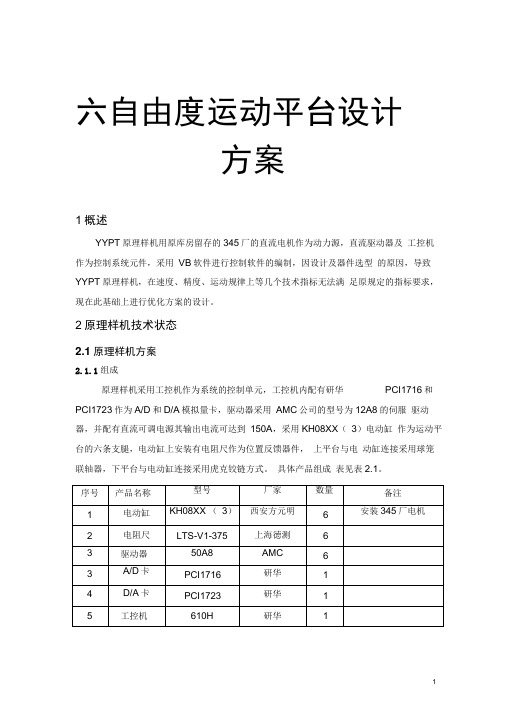
六自由度运动平台设计方案1概述YYPT原理样机用原库房留存的345厂的直流电机作为动力源,直流驱动器及工控机作为控制系统元件,采用VB软件进行控制软件的编制,因设计及器件选型的原因,导致YYPT原理样机,在速度、精度、运动规律上等几个技术指标无法满足原规定的指标要求,现在此基础上进行优化方案的设计。
2原理样机技术状态2.1原理样机方案2.1.1组成原理样机采用工控机作为系统的控制单元,工控机内配有研华PCI1716和PCI1723作为A/D和D/A模拟量卡,驱动器采用AMC公司的型号为12A8的伺服驱动器,并配有直流可调电源其输出电流可达到150A,采用KH08XX(3)电动缸作为运动平台的六条支腿,电动缸上安装有电阻尺作为位置反馈器件,上平台与电动缸连接采用球笼联轴器,下平台与电动缸连接采用虎克铰链方式。
具体产品组成表见表2.1。
2.1.2结构方案六自由度运动平台是由六条电动缸通过虎克铰链和球笼万向节联轴器将上、下两个平台连接而成,下平台固定在基础上,借助六条电动缸的伸缩运动,完成上平台在三维空间六个自由度(X,丫,Z,a,B, 丫)的运动,从而可以模拟出各种空间运动姿态。
图1六自由度平台外形图a)球笼联轴器(如图2所示)采用球笼铰链与上平面连接。
球笼铰链结构简单、体积小、运转灵活、易于维护。
初选球笼铰链型号BJB (JB/T6139-1992),公称转矩Tn=2000N/m,工作角度40度,外径D=68mm,轴孔选用圆柱孔d=24mm,总长度L1=148mm ,转动惯量为0.00008kg.m2,重量5kg。
图2球笼联轴器b)虎克铰链(如图3所示)采用虎克铰链与下平面连接。
万向节铰链传动效率高,允许两轴间的角位移大,适用于有大角位移的两轴之间的连接,一般两轴的轴间角最大可达35o~45o,噪音小,对润滑要求不高,传递转矩大,而且使用可靠,因此获得广泛的应用。
图3虎克铰链F固定板的连接(如图4所示)F 固定板与电动缸用法兰连接初选深沟球轴承型号61808 (GB/T276-1994),额定载荷 Cr=5.1kN ,外径D=52mm ,轴承孔选用 d=40mm ,宽 B=7mm ,重量 0.26kg 。
PCI-1761

CopyrightThis documentation and the software included with this product are copy-righted 2001 by Advantech Co., Ltd. All rights are reserved. Advantech Co., Ltd. reserves the right to make improvements in the productsdescribed in this manual at any time without notice. No part of this man-ual may be reproduced, copied, translated or transmitted in any form or by any means without the prior written permission of Advantech Co., Ltd.Information provided in this manual is intended to be accurate and reli-able. However, Advantech Co., Ltd. assumes no responsibility for its use, nor for any infringements of the rights of third parties which may result from its use.AcknowledgmentsPC-LabCard is a trademark of Advantech Co., Ltd. IBM and PC aretrademarks of International Business Machines Corporation. MS-DOS, Windows, Microsoft Visual C++ and Visual BASIC are trademarks of Microsoft Corporation. Intel and Pentium are trademarks of Intel Corpo-ration. Delphi and C++ Builder are trademarks of Inprise Corporation. CE notificationThe PCI-1761, developed by ADVANTECH CO., LTD., has passed the CE test for environmental specifications when shielded cables are used for external wiring. We recommend the use of shielded cables. This kind of cable is available from Advantech. Please contact your local supplier for ordering information.On-line Technical SupportFor technical support and service, please visit our support website at:/supportNote:✎Concerning saving the environment, we'd like to reduce the paper used for the user's manuals. Starting with Appendix C, pleasefind the PDF file on the CD-ROM.Part No. 2003176100 1st EditionPrinted in Taiwan November 2001Table of ContentsContentsChapter 1 Introduction (1)1.1 Features (1)1.2 Applications (3)1.3 Installation Guide (3)1.4 Software Overview (5)1.5 DLL Driver Programming Roadmap (6)1.6 Accessories (8)Chapter 2 Installation (9)2.1 Unpacking (9)2.2 Switch and Jumper Settings (11)2.3 I/O connectors (12)2.4 Driver Installation (13)2.5 Hardware Installation (15)2.6 Device Setup & Configuration (17)Chapter 3 Signal Connections (21)3.1 Overview (21)3.2 Isolated Digital Input Connections (21)3.3 Relay connections (22)Appendix A Specifications (23)Appendix B Block diagram (25)Appendix C Register Structure and Format (26)C.1 Overview (26)C.2 I/O Port Address Map (26)C.3 Relay I/O Registers - BASE+0H (28)C.4 Isolated Digital Input Registers - BASE+1H (29)C.5 Board ID - BASE+2H (29)C.6 Interrupt Status Register - BASE+3H/4H/5H (30)C.7 Interrupt Control Register - BASE+3H/4H/5H (31)Advantech Co., Ltd.iii PCI-1761 User’s Manual Advantech Co., Ltd.iv PCI-1761 User’s Manual Advantech Co., Ltd.1PCI-1761 User’s Manual Chapter 1.Chapter 1 IntroductionThank you for buying the Advantech PCI-1761. The Advantech PCI-1761 is a 8-channel relay actuator and 8-channel isolated digital input card for the PCI bus.Its eight on-board SPDT relays are ideal for applications such as device ON/OFF control or small power switched. For easy monitoring, each relay is equipped with one red LED to show its ON/OFF status.The PCI-1761's eight optically-isolated digital input channels are ideal for digital input in noisy environments or with floating potentials.The following sections of this chapter will provide further information about features, installation guide, together with some brief information on software and accessories for the PCI-1761 card.1.1 Features❏ 8 relay output channels and 8 isolated digital input channels ❏LED indicators to show activated relays ❏ 4 Form A-type and 4 Form C-type relay output channels ❏ Output status read-back ❏ Keep relay output values when hot system reset ❏ High-voltage isolation on input channels (3,750 V DC )❏ High ESD protection (2,000 V DC )❏ High over-voltage protection (70 V DC )❏ Wide input range (10 ~ 50 V DC )❏ Interrupt handling capability ❏ Board IDThe Advantech PCI-1761 offers the following main features:Robust ProtectionThe PCI-1761 digital input channels feature a robust isolation protection for industrial, lab and machinery automation applications. It durably withstands voltage up to 3,750 V DC , preventing your host system fromChapter 1 IntroductionPCI-1761 User’s Manual 2Advantech Co., Ltd.any incidental harms. If connected to an external input source with surge-protection, the PCI-1761 can offer up to a maximum of 2,000 V DC ESD (Electrostatic Discharge) protection. Even with an input voltage rising up to 70 V DC , the PCI-1761 can still manage to work properly albeit only for short period of time.Wide Input RangeThe PCI-1761 has a wide range of input voltage from 10 to 50 V DC , and it is suitable for most industrial applications with 12 V DC , 24 V DC and 48 V DC input voltage.Reset Protection Fulfills Requirement for Industrial ApplicationsWhen the system has undergone a hot reset (i.e. without turning off the system power), the PCI-1761 can either retain outputs values of each channel, or return to its default configuration as open status, depending on its on-board jumper setting. This function protects the system from wrong operations during unexpected system resets.Plug-and-Play FunctionThe PCI-1761 is a Plug-and-Play device, which fully complies with PCI Specification Rev 2.2. During card installation, there is no need to set jumpers or DIP switches. Instead, all bus-related configurations such as base I/O address and interrupt are automatically done by the Plug-and-Play function.Board IDThe PCI-1761 has a built-in DIP Switch that helps define each card's ID when multiple PCI-1761 cards have been installed on the same PC chas-sis. The board ID setting function is very useful when users build their system with multiple PCI-1761 cards. With correct Board ID settings, you can easily identify and access each card during hardware configura-tion and software programming.Note:✎For detailed specifications of the PCI-1761, please refer to Appendix A, Specifications.Advantech Co., Ltd.3PCI-1761 User’s Manual 1.2 Applications ❏ Industrial On/Off control ❏ Switch status sensing ❏ Digital I/O control ❏ Industrial and lab automation ❏ SMT/PCB machinery ❏ Semi-conductor machinery ❏ PC-based Industrial Machinery ❏ Testing & Measurement ❏ Laboratory & Education ❏ External relay driving 1.3 Installation Guide Before you install your PCI-1761 card, please make sure you have the following necessary components:❏ PCI-1761 card ❏ PCI-1761 User's Manual ❏ Driver software Advantech DLL drivers (included in the companion CD-ROM❏ Wiring cable PCL-10137 (optional)❏ Wiring board PCLD-880, ADAM-3937 (optional)❏ Computer Personal computer or workstation with a PCI-bus slot (running Windows 95/98/NT/2000)Some other optional components are also available for enhanced opera-tion:❏ Application software ActiveDAQ, GeniDAQ or other third-party software packagesAfter you get the necessary components and maybe some of the accesso-ries for enhanced operation of your Multifunction card, you can then begin the Installation procedures. Figure 1-1 provides a concise flow chart to give users a broad picture of the software and hardware installa-tion procedures.Chapter 1 IntroductionFig. 1-1: Installation Flow ChartPCI-1761 User’s Manual4Advantech Co., Ltd.1.4 Software OverviewAdvantech offers a rich set of DLL drivers, third-party driver support and application software to help fully exploit the functions of your PCI-1761 card:z DLL driver (on the companion CD-ROM)z LabVIEW driverz Advantech ActiveDAQz Advantech GeniDAQProgramming choices for DA&C cards: You may use Advantech applica-tion software such as Advantech DLL driver. On the other hand,advanced users are allowed another option for register-level program-ming, although not recommended due to its laborious and time-consum-ing nature.DLL DriverThe Advantech DLL Drivers software is included on the companion CD-ROM at no extra charge. It also comes with all the Advantech DA&C cards. Advantech's DLL driver features a complete I/O function library to help boost your application performance. The Advantech DLL driver for Windows 95/98/NT/2000 works seamlessly with development tools such as Visual C++, Visual Basic, Inprise C++ Builder and Inprise Delphi. Register-level ProgrammingRegister-level programming is reserved for experienced programmers who find it necessary to write codes directly at the level of device regis-ters. Since register-level programming requires much effort and time, we recommend that you use the Advantech DLL drivers instead. However, if register-level programming is indispensable, you should refer to the rele-vant information in Appendix C, Register Structure and Format, or to the example codes included on the companion CD-ROM.Advantech Co., Ltd.5PCI-1761 User’s Manual Chapter 1 IntroductionPCI-1761 User’s Manual 6Advantech Co., Ltd. 1.5 DLL Driver Programming RoadmapThis section will provide you a roadmap to demonstrate how to build an application from scratch using Advantech DLL driver with your favorite development tools such as Visual C++, Visual Basic, Delphi and C++ Builder. The step-by-step instructions on how to build your own applica-tions using each development tool will be given in the DLL Drivers Man-ual . Moreover, a rich set of example source codes are also given for your reference.Programming ToolsProgrammers can develop application programs with their favorite devel-opment tools:❏ Visual C++❏ Visual Basic ❏ Delphi ❏ C++ Builder For instructions on how to begin programming works in each develop-ment tool, Advantech offers a Tutorial Chapter in the DLL Drivers Man-ual for your reference. Please refer to the corresponding sections in this chapter on the DLL Drivers Manual to begin your programming efforts. You can also take a look at the example source codes provided for each programming tool, since they can get you very well-oriented.The DLL Drivers Manual can be found on the companion CD-ROM. Or if you have already installed the DLL Drivers on your system, The DLL Drivers Manual can be readily accessed through the Startbutton:Start/Programs/Advantech Driver for 95 and 98 (or for NT/2000)/ Driver ManualThe example source codes could be found under the corresponding instal-lation folder such as the default installation path:\Program Files\Advantech\ADSAPI\ExamplesFor information about using other function groups or other development tools, please refer to the Creating Windows 95/98/NT/2000 Application with DLL Driver chapter and the Function Overview chapter in the DLL Drivers Manual.Advantech Co., Ltd.7PCI-1761 User’s Manual Programming with DLL Driver Function LibraryAdvantech DLL driver offers a rich function library to be utilized in vari-ous application programs. This function library consists of numerous APIs that support many development tools, such as Visual C++, Visual Basic, Delphi and C++ Builder.According to their specific functions or services, those APIs can be cate-gorized into several function groups:❏ Digital Input/Output Function Group ❏ Counter Function Group ❏ Port Function Group (direct I/O)❏ Event Function Group For the usage and parameters of each function, please refer to the Func-tion Overview chapter in the DLL Drivers Manual.Troubleshooting DLL Driver ErrorDriver functions will return a status code when they are called to perform a certain task for the application. When a function returns a code that is not zero, it means the function has failed to perform its designated func-tion. To troubleshoot the DLL driver error, you can pass the error code to DRV_GetErrorMessage function to return the error message. Or you can refer to the DLL Driver Error Codes Appendix in the DLL Drivers Manual for a detailed listing of the Error Code, Error ID and the Error Message.Chapter 1 IntroductionPCI-1761 User’s Manual 8Advantech Co., Ltd. 1.6 AccessoriesAdvantech offers a complete set of accessory products to support the PCI-1761 card. These accessories include:Wiring CablePCL-10137 The PCL-10137 shielded cable is specially designedfor PCI-1761 cards to provide high resistance tonoise. To achieve a better signal quality, the signalwires are twisted in such a way as to form a "twisted-pair cable", reducing cross-talk and noise from othersignal sources. Furthermore, its analog and digitallines are separately sheathed and shielded to neutralize EMI/EMC problems.Wiring Boards❏ ADAM-3937 The ADAM-3937 is a 37-pin D-type wiring terminal module for DIN-rail mounting. This terminal modulecan be readily connected to the Advantech PC-Labcards and allow easy yet reliable access to individualpin connections for the PCI-1761 card.❏ PCLD-880The PCLD-880 is a universal screw-terminal board to be used with any of the PC-LabCards which have37-pin D-type connectors.Advantech Co., Ltd.9PCI-1761 User’s Manual Chapter 2 InstallationThis chapter gives users a package item checklist, proper instructions about unpacking and step-by-step procedures for both driver and card installation. 2.1 UnpackingAfter receiving your PCI-1761 package, please inspect ita contents first. The package should contain the following items:5 PCI-1761 card5 Companion CD-ROM (DLL driver included)5 User's ManualThe PCI-1761 card harbors certain electronic components vulnerable to electrostatic discharge (ESD). ESD could easily damage the integrated circuits and certain components if preventive measures are not carefully paid attention to.Before removing the card from the antistatic plastic bag, you should take the following precautions to ward off possible ESD damage:z Touch the metal part of your computer chassis with your hand to dis charge static electricity accumulated on your body. Or one can also use a grounding strap.z Touch the anti-static bag to a metal part of your computer chassis before opening the bag.z Take hold of the card only by the metal bracket when removing it out of the bag.Chapter 2.Chapter 2 InstallationPCI-1761 User’s Manual 10Advantech Co., Ltd.After taking out the card, you should first:z Inspect the card for any possible signs of external damage (loose or damaged components, etc.). If the card is visibly damaged, pleasenotify our service department or our local sales representativeimmediately. Avoid installing a damaged card into your system.Also pay extra caution to the following aspects to ensure proper instal-lation:a Avoid physical contact with materials that could hold static electricity such as plastic, vinyl and Styrofoam.a Whenever you handle the card, grasp it only by its edges. DO NOTTOUCH the exposed metal pins of the connector or the electroniccomponents.Note:✎Keep the anti-static bag for future use. You might need the originalbag to store the card if you have to remove the card from PC or trans port it elsewhere.2.2 Switch and Jumper Settings The PCI-1761 card has one function switch settings.Fig.2-1: Card connector, jumper and switch locationsTable 2-1: Summary of jumper settingsSetting the time to reset the relay outputsSome users will want the capability of clearing each relay output when the system (or PC) issues a reset signal on the PCI bus. Some users will want to clear their relays only as part of system power-on. The PCI-1761 satisfies both these needs by providing jumper JP2. Depending on theapplication, this capability may allow relay outputs to be "OFF" without requiring a complete shutdown of processes controlled by the card. Advantech Co., Ltd.11PCI-1761 User’s Manual Chapter 2 InstallationPCI-1761 User’s Manual 12Advantech Co., Ltd. 2.3 I/O connectors Pin AssignmentsFigure 2-2 shows the pin assignments for the 37-pin I/O connector on the PCI-1761Description of pin use:R0_NOIDI n A* (n =0 ~ 7):Isolated digital input AR0_NC IDI n B* (n =0 ~ 7):R1_NO Isolated digital input BR n _NO(n =0 ~ 7):R1_NC Normally Open pin of relay outputR2_NO R n _NC(n =0 ~ 7):Normally Close pin of relay outputR2_NC R n _COM(n =0 ~ 7):R7_NO Common pin of relay output IDI 0AIDI 1AIDI 2AIDI 3AIDI 4ANote:IDI 5A Isolated Digital Input is bidiretional.IDI 6AIDI 7AAdvantech Co., Ltd.13PCI-1761 User’s Manual 2.4 Driver InstallationNote:✎We recommend you to install the driver before you install the PCI-1761 card into your system, since this will guarantee a smooth instal lation process.The 32-bit DLL driver Setup program for the PCI-1761 card is included on the companion CD-ROM that is shipped with your DA&C card pack-age. Please follow the steps below to install the driver software:Step 1: Insert the companion CD-ROM into your CD-ROM drive.Step 2: The Setup program will be launched automatically if you havethe autoplay function enabled on your system. When the SetupProgram is launched, you'll see the following Setup Screen.Note:✎If the autoplay function is not enabled on your computer, use Windows Explorer or Windows Run command to execute SETUP.EXE on the companion CD-ROM.Fig. 2-3 The Setup Screen of Advantech Automation SoftwareChapter 2 InstallationPCI-1761 User’s Manual 14Advantech Co., Ltd.Step 3: Select the DLL Drivers option.Step 4: Select the Windows 95/98 or Windows NT or Windows 2000option according to your operating system. Just follow the installation instructions step by step to complete your DLL driversetup.Fig. 2-4 Different options for Driver SetupFor further information on driver-related issues, an online version of DLL Drivers Manual is available by accessing the following path:Start/Programs/Advantech Driver for 95 and 98 (or for NT/2000)/Driver ManualAdvantech Co., Ltd.15PCI-1761 User’s Manual 2.5 Hardware InstallationNote:✎Make sure you have installed the driver first before you install thecard (please refer to 2.4 Driver Installation )After the DLL driver installation is completed, you can now go on to install the PCI-1761 card in any PCI slot on your computer. But it is sug-gested that you should refer to the computer user manual or related docu-mentation if you have any doubt. Please follow the steps below to install the card on your system.Step 1: Turn off your computer and unplug the power cord and cables.TURN OFF your computer before installing or removing anycomponents on the computer.Step 2: Remove the cover of your computer.Step 3: Remove the slot cover on the back panel of your computer.Step 4: Touch the metal part on the surface of your computer to neutralize the static electricity that might be on your body.Step 5:Insert the 1761 card into a PCI slot. Hold the card only by itsedges and carefully align it with the slot. Insert the card firmlyinto place. Use of excessive force must be avoided, otherwise the card might be damaged.Step 6:Fasten the bracket of the PCI card on the back panel rail of thecomputer with screws.Step 7:Connect appropriate accessories (37-pin cable, wiring terminals,etc. if necessary) to the PCI card.Step 8:Replace the cover of your computer chassis. Re-connect thecables you removed in step 2.Step 9:Plug in the power cord and turn on the computer .Note:✎In case you installed the card without installing the DLL driver first,Windows 95/98 will recognize your card as an "unknown device" after rebooting, and will prompt you to provide the necessary driver. You should ignore the prompting messages (just click the Cancel button) and set up the driver according to the steps described in 2.4 Driver Installation.Chapter 2 InstallationPCI-1761 User’s Manual 16Advantech Co., Ltd. After the PCI-1761 card is installed, you can verify whether it is properly installed on your system in the Device Manager :1. Access the Device Manager through Control Panel/System/Device Manager.2. The device name of the PCI-1761 should be listed on the Device Man-ager tab on the System Property Page . Fig. 2-5 The device name listed on the Device ManagerNote:✎If your card is properly installed, you should see the device name of your card listed on the Device Manager tab. If you do see yourdevice name listed on it but marked with an exclamation sign"!", it means your card has not been correctly installed. In this case, remove the card device from the Device Manager by selecting its device name and press the Remove button. Then gothrough the driver installation process again.After your card is properly installed on your system, you can now config-ure your device using the Device Installation Program that has itselfalready been installed on your system during driver setup. A complete device installation procedure should include device setup, configuration and testing. The following sections will guide you through the Setup,Configuration and Testing of your device.2.6 Device Setup & ConfigurationThe Device Installation program is a utility that allows you to set up, con-figure and test your device, and later stores your settings on the system registry. These settings will be used when you call the APIs of Advantech 32-bit DLL drivers.Setting Up the DeviceStep 1:To install the I/O device for your card, you must first run the Device Installation program (by accessing Start/Programs/Advantech Driver for 95 and 98 (or for NT/2000)/Device Installation).Fig. 2-6 The Advantech Device Installation utility program Advantech Co., Ltd.17PCI-1761 User’s Manual Chapter 2 InstallationPCI-1761 User’s Manual 18Advantech Co., Ltd.Step 2: On the Device Installation program window, select the Setupmenu item on the menu bar, and click the Device command (Fig.2-6) to bring up the I/O Device Installation dialog box (Fig. 2-7).You can then view the device(s) already installed on your system(if any) on the Installed Devices list box. Since you haven'tinstalled any device yet, you might see a blank list such as the onein (Fig. 2-6).Fig. 2-7 The I/O Device Installation dialog boxStep 3: Scroll down the List of Devices box to find the device that youwish to install, then click the Add … button to evoke the Device(s)found dialog box such as one shown in Fig. 2-8. The Device(s)found dialog box lists all the installed devices on your system.Select the device you want to configure from the list box andpress the OK button. After you have clicked OK , you will see aDevice Settingdialog box such as the one in Fig. 2-9.Advantech Co., Ltd.19PCI-1761 User’s Manual Fig. 2-8 The "Device(s) Found" dialog boxConfiguring the DeviceStep 4: On the Device Setting dialog box (Fig. 2-9), you can configurethe ID0 ~ ID7 Interrupt trigger mode either as Rising Edge orFalling Edge , and Enable or Disable the ID0 ~ ID7.Fig. 2-9 The Device Setting dialog boxStep 5: After you have finished configuring the device, click OK and thedevice name will appear in the Installed Devices box as seenin Fig. 2.10Chapter 2 InstallationPCI-1761 User’s Manual 20Advantech Co., Ltd.Fig. 2-10 The Device Name appearing on the list of devices boxNote:✎As we have noted, the device name "000:PCI-1761 I/O=6500H" begins with a device number "000", which is specifically assigned toeach card. The device number is passed to the driver to specifywhich device you wish to control.After your card is properly installed and configured, you can click the Test… button to test your hardware by using the testing utility we sup-plied. For more detailed information, please refer to Chapter 2 of the DLL Drivers Manual .You can also find the useful examples on the CD-ROM to speed up yourprogramming.Advantech Co., Ltd.21PCI-1761 User’s Manual Chapter 3.Chapter 3 Signal Connections 3.1 OverviewMaintaining signal connections is one of the most important factors in ensuring that your application system is sending and receiving data cor-rectly. A good signal connection can avoid unnecessary and costly dam-age to your PC and other hardware devices. This chapter provides useful information about how to connect input and output signals to the PCI-1761 via the I/O connector.3.2 Isolated Digital Input ConnectionsThe PCI-1761 has 8 isolated digital input channels designatedIDI0~IDI7.Each of isolated digital input channel accepts 10~50 V DC voltageinputs, and accept bi-directional input. It means that you can apply positive or negative voltage to an isolated input pin (Vin ). The figure below shows how to connect an external input source to one of the card's isolated input channelsFigure 3-1: Isolated digital input connectionsChapter 3 Signal Connections3.3 Relay connectionsAfter power on, the initial relay output status of PCI-1761 is shown asbelow:Figure 3-2: Relay output connectionA write operation to I/O address, BASE +0, will change the outputstatus of each relay. For example, if Bit 0 of BASE +0 is set "1" (logic high), relay 0, K0, will switch from position "NORMALLY CLOSED", R0_NC, to position "NORMALLY OPEN", R0_NO. This means thatLOAD2 will be de-energized, while LOAD1 is energized.To summarize, the "COMMON" line connect to the "NORMALLYCLOSED" line, if the corresponding bit is set as 0 (power-on initialstatus). Otherwise, if the corresponding bit is set as 1, then the"COMMON" line will connect to the "NORMALLY OPEN" line..PCI-1761 User’s Manual22Advantech Co., Ltd.Advantech Co., Ltd.23PCI-1761 User’s Manual Appendix AAppendix A SpecificationsTable A-1: Isolated Digital InputTable A-2: Relay Output Number of Input Channel8Optical Isolation3750 V DC Opto-isolator response time25µs Over-voltage Protect70 V DC Input Voltage VIH (max.)50 V DC VIH (min.)10 V DC VIL (max.)3 V DC Input Current 10 V DC1.6 mA (typical)12 V DC1.9 mA (typical)24 V DC4.1 mA (typical)48 V DC8.5 mA (typical)50 V DC 8.9 mA (typical)Number of Output Channel8Relay TypeSPDT (4 Form C and 4 Form A)Rating (resistive)3 A* 250 V AC or 3 A* 24 V DC Max. Switching Power750 AV, 72 W Max. Switching Voltage250 V AC , 24 V DC Max. Switching Current3 A Min. Switching Load10mA 5V DC Breakdown Voltage5,000 V AC for 1 min. (Between coil and contacts)Operate time15 ms max.Release time5 ms max.Insulation Resistance1,000 M Ω min. (at 500 V DC )Life Expectancy Mechanical2x107 ops. min.Electrical 2x10⁵ ops. min.(contact rating)Appendix A SpecificationsPCI-1761 User’s Manual 24Advantech Co., Ltd.Note:✎The current was limited by the cable and wiring terminal board. For detailed relay specification, please refer toCD-ROM:\Document\ PCI-1761_Relay_Spec.pdf.Table A-3: General Specs I/O Connector Type 37-pin D-type female Dimensions 175 mm x 100 mm (6.9" x 3.9")Power Consumption +5V @ 220 mA (typical)+5V @ 750 mA (max.)TemperatureOperating0 ~ +60 °C (32 ~ 140°F)(refer to IEC 68-2-1,2)Storage-20 ~ +70 °C (-4 ~158 °F)5 - 95 % RH non-condensing (refer to IEC 68-2-3)Relative HumidityCertification CE Class A certified。
一种工控机高速采集SSI接口数据的方法靳红涛
收稿日期:2011-12-28一种工控机高速采集SSI 接口数据的方法靳红涛,赵勇进,张晓曦(中国兵器工业第二〇八研究所,北京102202)摘要:同步串行接口(SSI)具有速度快、连线简单、抗干扰能力强等优点,在工业控制等领域得到了越来越广泛的应用。
一般的工控机上不提供SSI 接口,市场上的SSI 接口扩展卡很少且价格昂贵。
介绍了SSI 并行接口模块SSI208P ,基于数字量输入/输出扩展卡和SSI208P ,给出了一种工控机高速采集多通道SSI 光电编码器数据的低成本实现方案,详细阐述了硬件和软件设计方法。
关键词:SSI ;光电编码器;工控机;数据采集Implementation of high speed SSI data acquisition by industrial control computerJIN Hong-tao ,ZHAO Yong-jin ,ZHANG Xiao-xi(No.208Research Institute of China Ordnance Industries,Beijing102202,C hina)Abstract:Synchronous Serial Interface (SSI)has such advantages as high transfer speed,simple connection,excellent noise proof feature and it is widely used in industrial control and other fields.However,SSI is not provided in most industrial control computers and the extended SSI cards are expensive and hard to find on the mark.Based on the SSI module of SSI208P and digital input/output card,a low cost implementation of multi SSI photoelectric encoder high speed data acquisition by industrial control computer is introduced.Hardware and software are given in detail.Keywords:SSI ;photoelectric encoder ;industrial control computer ;data acquisitionSSI (Synchronous Serial Interface)即同步串行接口,具有传输速度快、连线简单、抗干扰能力强等优点,在光电编码器等各种传感器上得到了广泛的应用[1,2]。
- 1、下载文档前请自行甄别文档内容的完整性,平台不提供额外的编辑、内容补充、找答案等附加服务。
- 2、"仅部分预览"的文档,不可在线预览部分如存在完整性等问题,可反馈申请退款(可完整预览的文档不适用该条件!)。
- 3、如文档侵犯您的权益,请联系客服反馈,我们会尽快为您处理(人工客服工作时间:9:00-18:30)。
如何在labview下使用研华板卡?(适用于所有 ISA 和PCI 系列模拟量和数字量采集卡)
答:研华所有das卡都可以在labview下使用。
Labview驱动是建立在32bitDLL驱动基础之上的,见下图。
所以要安装labview驱动先要安装32bitDLL驱动。
包括devicemanager和对应板卡的DLL 驱动,然后再安装对应的labview驱动。
具体步骤如下:
2.3.1.1 安装Device Manager和32bitDLL驱动
注意:测试板卡和使用研华驱动编程必须首先安装安装Device Manager和32bitDLL 驱动。
第一步:将启动光盘插入光驱;
第二步:安装执行程序将会自动启动安装,这时您会看到下面的安装界面:
图2-1
注意:如果您的计算机没有启用自动安装,可在光盘文件中点击autorun.exe文件启动安装程
第三步: 点击CONTINUE,出现下图界面(见图2-2)首先安装Device Manager。
也可以在光盘中执行\tools\DevMgr.exe直接安装。
图2-2
第四步:点击IndividualDriver,然后选择您所安装的板卡的类型和型号,然后按照提示就可一步一步完成驱动程序的安装。
图2-3
2.3.1.4 labview驱动程序安装使用说明
研华提供labview驱动程序。
注意:安装完前面步骤的Device Manager和32bitDLL 驱动后labview驱动程序才可以正常工作。
光盘自动运行点击Installation再点击Advance Options 出现以下界面(见图2-6)。
点击:
LavView Drivers来安装labview驱动程序和labview驱动手册和示例程序。
图2-6
安装完后labview驱动帮助手册快捷方式为:开始/ 程序/ Advantech Automation/LabView/XXXX.chm。
默认安装下也可以在C:\Program Files\National Instruments\LabVIEW 7.0\help\Advantech 中直接打开labview驱动帮助手册。
labview驱动示例程序默认安装在C:\Program Files\National Instruments\LabVIEW 7.0\examples\Advantech DAQ 目录下。