V型球阀说明书
电动V型陶瓷球阀 使用说明书(1)
产品使用说明书阀类:电动陶瓷调节球阀型号:VQ941TCXX 阀门有限公司XX V ALVE CO., LTD.1.主要用途和使用范围1.1用途该阀主要使用在电站排灰、矿山、化工等诸多工业管线上,特别固体颗粒管线上使用更广泛。
该类阀门可做开关阀或调节使用。
V形通道具有线性调节功能,流量与开度呈等比关系。
1.2使用范围温度(℃)-29~200 ;压力等级(MPa) ≤1.6 ;介质:干灰、渣浆等2.产品采用标准□ GB/T12237□ API 6D□ ASTM□ NACE 01754.主要结构特点:1.1 球体:球体沿垂直轴线廻转运动,浮动球结构。
4.2 阀座:□浮动式□压配式□其它4.3 阀杆:□暗杆旋转式□明杆升降式□阀杆旋转式□其它4.4阀门连接:□法兰式□焊接式□螺纹式□其它4.5中法兰连接:□法兰式□焊接式□内压自紧式□其它4.6阀杆密封:□填料+隔环□填料+“0”橡胶圈□“O”橡胶圈□其它4.7是否具有排放装置:有□无4.8阀门操作:□手动□电动□气动□液动□光杆□其它4.9手动时顺时针旋转为关,逆时针旋转为开。
其它型式驱动开关要与控制箱开关按钮和指示相一致,避免误操作。
如果有注入塞定期加注润滑油(脂)、密封脂、软质填料,确保阀门完好无渗漏。
通过排泄阀排放体腔多余介质和沉积物确保安全和设备完好运行。
4.10阀门结构紧凑,密闭,备有开关指示和机械限位,浮动阀座进口密封,阀门扭矩小。
阀座及通道内部衬陶瓷,密封可靠,耐磨损腐蚀。
5..2.3检查球面和阀座有无擦伤。
如有擦伤,需修复研合。
按方位重新装配好。
结构和外型(参考)6.主要零件及材料序号零件名称材料碳钢合金钢不锈钢1 阀体(左阀体)□ A 516 Gr70□A 216 WCB□ A 352 LCB□A105N□其它□ A 487-4Q□ A 352-LC3□ A 217 GrCA15□其它□ A 351 CF8□ A 351 CF8M□ A 744 CF3□ A 744 CF3M□其它7.安装和使用7.1.1 阀门安装位置要有利于操作和维护。
WT-5000气动活塞式V型调节球阀

附加规格(根据要求生产制造)·特殊检查,材料检查(制造记录表)无损检查,蒸气检查,低温检查·法兰背面加工·带排污栓·双重填料·蒸气夹套·禁油禁水处理·禁铜处理·特殊配管和接头·SUS304制品的外裸螺栓,螺母·盐害对策·防砂,防尘要求·热带地区规格·寒冷地区规格·真空(用途)性能额定Kv 值:参照第3页表2可调范围:100 :1允许压差:参照第3页表3阀座泄漏率(对于额定Kv值%):金属密封小于0.01%或0.001%(ANSI B16.104-1976Ⅳ级)软密封小于0.00001%以下(ANSI B16.104-1976Ⅵ级)回差:小于全行程的1%(带定位器)小于全行程的3%~5%(不带定位器)基本误差:小于全行程的±1%(带定位器)小于全行程的±5%(不带定位器)动作时间:参照第3页表2外形尺寸:参照第6页表4产品重量:参照第6页表4型号编制:参照第6页型号编制油漆颜色:调节阀的气动执行机构和阀的表面应涂漆,不锈钢和铜的阀可不涂漆。
阀体上的箭头及文字涂红漆。
用户指定色彩也可。
表1阀体,阀内件材料的配套及工作温度范围(℃)注1)用途为空化/闪蒸,禁油及要求保持关闭性能的调节阀,不管工作温度和压差如何,建议使用堆焊司太莱合金。
2)要符合高压气体管理法的条件,*标记的工作温度限于350℃。
3) 黑粗线框为阀体材料和阀内件材料的标准配置。
表2 Kv值动作时间公称通径DN(mm) 25 32 40 50 65 80 100 125 150 200 250 300 额定流量系数Kv 22 36 58 82 145 200 355 554 798 1600 2500 4000 执行机构型号GTX75 GTX92 GTX118 GTX160 GTX210GTX254GTX255GTX300全开0.5 0.5/0.6 0.5/0.6 0.5/0.6 0.7/1.0 0.8/1.0 1.0/1.2 1.1/1.6 1.2/2.0 3.5/4.5 4.0/5.0 5.0/6.0 动作时间(s)全闭0.5 0.6/0.8 0.6/1.0 0.8/1.2 0.8/1.2 1.0/1.5 1.0/2.0 1.3/2.3 1.5/2.5 4.5/6.0 5.0/6.0 5.5/7.0 注1)表中数据为标准配置,可配用不同执行机构改变动作时间。
Triac “V” Series控制口球阀商品介绍说明书
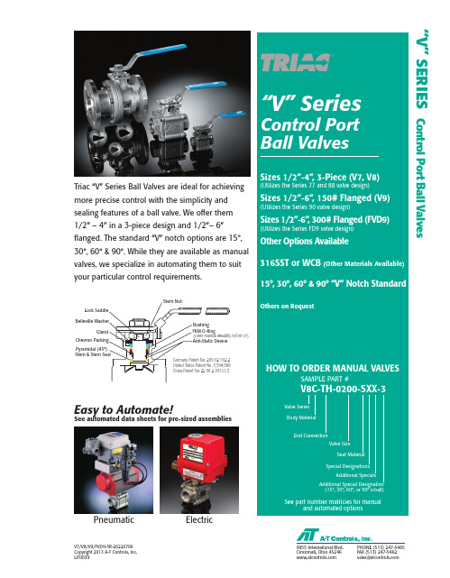
“V” SERIESControl Port Ball ValvesTriac “V” Series Ball Valves are ideal for achievingmore precise control with the simplicity andsealing features of a ball valve. We offer them1/2” – 4” in a 3-piece design and 1/2”– 6”flanged. The standard “V” notch options are 15°,30°, 60° & 90°. While they are available as manualvalves, we specialize in automating them to suityour particular control requirements.Pyramidal (45°)Easy to Automate!See automated data sheets for pre-sized assembliesPneumatic ElectricCincinnati, Ohio 45246FAX (513) 247-5462******************** V7/V8/V9/FVD9-3R-20220706Copyright 2013 A-T Controls, Inc.LIT0039V7 3-Piece Flow Coefficients - Cv ChartPercent OpenValve Standards2 V7/V8/V9/FVD9-3R-20220706 | Copyright 2013 A-T Controls, Inc. | | (513) 247-5465V8 3-Piece & V9 Flanged Flow Coefficients - Cv ChartPercent Open3V7/V8/V9/FVD9-3R-20220706 | Copyright 2013 A-T Controls, Inc. | | (513) 247-5465Triac “V” port control valves areavailable with 15°, 30°, 60°, & 90° V-notch options. V-port valves o ffer better and more consistent controlt han traditional round ported ball valves. We offer this valve with the control port c ast and machined into the ball, not in t he seat. This allows for much better flow characteristics and eliminates the need to replace seats. The 15° and 30° option allows for finer tapered control throughout the valve rotation, and the 60° & 90° offer a larger Cv in addition to controlled flow.The PTFE seat is standard in the V7 valves, while the 50/50 STFE seat is standard with V8, V9, and FVD9 V-port valves. The 50% 316SST powder and 50% PTFE offers both strength andsuperior sealing properties.30° V-Port15° V-Port60° V-Port90° V-PortNote: May be customized;call factory for flow analysis design.V-Notch Options: 15°, 30°, 60°, & 90°4V7/V8/V9/FVD9-3R-20220706 | Copyright 2013 A-T Controls, Inc. | | (513) 247-54655V7 Series 3-Piece V-Port Control Valve(V7 utilizes the reliable 77-Series design by adding a V-Ball for controllability)3-PieceSanitary End Ball Valve Tube Pipe Design With or without cavity filler 240 Grit Internal Polish Standard (15-20 RA)MATERIALS LIST# FOR 1/2”-3” - 4 PCS ; FOR 4” - 6 PCS& FOR 1/2”-2” - 4 PCS ; FOR 2-1/2”-3” - 8 PCS; FOR 4” - 12 PCS**FOR 1/2”-2” - ASTM A193 GRADE B8; FOR 2-1/2”-4” - ISO 3506-1 A2-70## FOR 1/2”-2” - ASTM A194 GRADE 8; FOR 2-1/2”-4” - ISO 3506-2 A2-70DIMENSIONS (IN)Tube O.D. according to ASME BPE 2019PATHV7/V8/V9/FVD9-3R-20220706 | Copyright 2013 A-T Controls, Inc. | | (513) 247-5465Published torques are based onfull differential pressure withclean water with 25% safetyadded. Consult the ApplicationSizing Guide for assistance withsizing actuators.PRESSURE IN BARNOTE: At temperature, valves arelimited by either the valve body/endcap pressure ratings, seat pressureratings, or packing/stem seal/gaskets;whichever is lower.6 V7/V8/V9/FVD9-3R-20220706 | Copyright 2013 A-T Controls, Inc. | | (513) 247-54657High Performance, Full Port 3-Piece Ball ValveISO 5211 Direct Mount1000 thru 2000 psi(by size) 1/2” to 4” V8 Series 3-PieceV-Port Control ValveNOTE: SIZES 2-1/2” THRU 4” INCLUDE SEAT RETAINER RINGS.^ PACKING SET* 1/2” THRU 1-1/2” QTY = 4 PCS * 2” THRU 4” QTY = 6 PCS# 1/2” THRU 1-1/2” QTY = 4 PCS # 2” QTY = 6 PCS# 2-1/2” THRU 4” QTY = 12 PCSFLOW PATHV7/V8/V9/FVD9-3R-20220706 | Copyright 2013 A-T Controls, Inc. | | (513) 247-5465(V8 utilizes the reliable 88-Series design by adding a V-Ball for controllability)V8 Series 3-Piece V-Port Control ValveHigh Performance, Full Port 3-Piece Ball ValveISO 5211 Direct Mount1000 thru 2000 psi(by size)1/2” to 4” *ASME Boiler Pressure Vessel Code8V7/V8/V9/FVD9-3R-20220706 | Copyright 2013 A-T Controls, Inc. | | (513) 247-54659V9 Series ASME Class 150 Flanged V-Port Control ValveHigh Performance, Full Port Split Body Flanged Ball Valve Series V9 (ASME Class 150)DIMENSIONS (IN)INVESTMENT CAST BODY (Series V9)“V” Series 6” 150# Flanged Mounting DimensionsV7/V8/V9/FVD9-3R-20220706 | Copyright 2013 A-T Controls, Inc. | | (513) 247-5465Published torques are based on full differential pressure with clean water with 25% safety added. Consult theApplication Sizing Guide for assistance with sizing actuators.NOTE: At temperature, valves are limited by either the valve body/end cap pressure ratings, seat pressure ratings, or packing/stem seal/gaskets; whichever is lower.10V7/V8/V9/FVD9-3R-20220706 | Copyright 2013 A-T Controls, Inc. | | (513) 247-546511High Performance, Full Port 300# Flanged, Split Body Ball Valve Series FVD9-F3 (ASME Class 300)FVD9 Series ASME Class 300 Flanged V-Port Control ValveDIMENSIONS (IN)MATERIALS LISTNOTE: A-T CONTROLS RECOMMENDS A GEAR FOR 6” VALVES ANDLARGERFLOWPATHV7/V8/V9/FVD9-3R-20220706 | Copyright 2013 A-T Controls, Inc. | | (513) 247-5465(FVD9 utilizes the reliable FD9-Series design by adding a V-Ball for controllability)12V7/V8/V9/FVD9-3R-20220706Copyright 2013 A-T Controls, Inc.LIT0039。
SV230A-RE 电动球阀操纵机说明书

SV230A-REGlobe valve actuator for 2-way and 3-way globevalves• Actuating force 1500 N• Nominal voltage AC 100...240 V• Control Open/close, 3-point• Stroke 20 mmTechnical dataElectrical data Nominal voltage AC 100...240 VNominal voltage frequency50/60 HzNominal voltage range AC 85...265 VPower consumption in operation 2 WPower consumption in rest position 1 WPower consumption for wire sizing 4 VAConnection supply / control Terminals 4 mm² (cable ø4...10 mm)Parallel operation Yes (note the performance data)Functional data Actuating force motor1500 NManual override with push-button, can be lockedStroke20 mmRunning time motor150 s / 20 mmSound power level, motor35 dB(A)Position indication Mechanical, 5...20 mm strokeSafety data Protection class IEC/EN II, reinforced insulationPower source UL Class 2 SupplyDegree of protection IEC/EN IP54Degree of protection NEMA/UL NEMA 2Enclosure UL Enclosure Type 2EMC CE according to 2014/30/EULow voltage directive CE according to 2014/35/EUCertification IEC/EN IEC/EN 60730-1 and IEC/EN 60730-2-14UL Approval cULus according to UL60730-1A, UL60730-2-14and CAN/CSA E60730-1The UL marking on the actuator depends onthe production site, the device is UL-compliantin any caseType of action Type 1Rated impulse voltage supply / control4 kVPollution degree3Ambient humidity Max. 95% RH, non-condensingAmbient temperature0...50°C [32...122°F]Storage temperature-40...80°C [-40...176°F]Servicing maintenance-freeWeight Weight 1.9 kgSV230A-RE••••••Safety notesThis device has been designed for use in stationary heating, ventilation and air-conditioning systems and must not be used outside the specified field of application, especially in aircraft or in any other airborne means of transport.Outdoor application: only possible in case that no (sea) water, snow, ice, insolation or aggressive gases interfere directly with the device and that it is ensured that the ambient conditions remain within the thresholds according to the data sheet at any time.Only authorised specialists may carry out installation. All applicable legal or institutional installation regulations must be complied with during installation.The switch for changing the direction of motion and so the closing point may be adjusted only by authorised specialists. The direction of motion is critical, particularly in connection with frost protection circuits.The device may only be opened at the manufacturer's site. It does not contain any parts that can be replaced or repaired by the user.The device contains electrical and electronic components and must not be disposed of as household refuse. All locally valid regulations and requirements must be observed.Product featuresMounting on third-party valvesThe RetroFIT+ actuators for installation on a wide range of valves from various manufacturers are comprised of an actuator, bracket, universal valve neck adapter and universal valve stem adapter. Adapt the valve neck and valve stem to begin with, then attach the RetroFIT+ bracket to the valve neck adapter. Now fit the RetroFIT+ actuator into the bracket and connect it to the valve. Whilst taking the position of the valve closing point into account, secure the actuator to the bracket and then conduct the commissioning process. The valve neck adapter/actuator can be rotated by 360° on the valve neck, provided the size of the installed valve permits.Mounting on Belimo valvesUse standard actuators from Belimo for mounting on Belimo globe valves. The installation of RetroFIT+ actuators on Belimo globe valves is technically possible.Manual overrideManual override with push-button possible (the gear train is disengaged for as long as the button is pressed or remains locked).The stroke can be adjusted by using a hexagon socket screw key (4 mm), which is inserted into the top of the actuator. The stroke shaft extends when the key is rotated clockwise.High functional reliabilityThe actuator is overload protected, requires no limit switches and automatically stops when the end stop is reached.Home positionFactory setting: Actuator stem is retracted.Setting direction of motionWhen actuated, the stroke direction switch changes the running direction in normal operation.AccessoriesElectrical accessories DescriptionType Auxiliary switch 2x SPDT add-on S2A-H Mechanical accessoriesDescriptionType Spacer ring for LDM, stroke 20 mm ZNV-203Spacer ring for Sauter, stroke 20 mm ZNV-204Adapter kit DanfossZNV-205Electrical installationCaution: Power supply voltage!Parallel connection of other actuators possible. Observe the performance data.Direction of stroke switch factory setting: Actuator stem retracted (▲).SV230A-REWiring diagrams AC 230 V, open/closeAC 230 V, 3-pointElectrical installationOperating controls and indicators1Direction of stroke switch Switch over:Direction of stroke changes4Manual override button Press button:Gear train disengages, motor stops, manual override possible Release button:Gear train engages, standard mode10Manual override Clockwise:Actuator stem extends Counterclockwise:Actuator stem retractsSV230A-RE DimensionsFurther documentation• Installation instructions for actuators。
ACTIVAL 二通调节球阀 VY5302A 说明书

二通调节球阀VY5302A(带螺纹连接的青铜阀体)概要ACTIVAL VY5302A 是带有螺纹连接的二通球阀产品。
本产品按比例对冷/热水进行调节,用于HVAC(供热通风与空调工程)控制。
VY5302A具有青铜阀体、不锈钢球体(阀塞)和阀杆、及其他具有防腐蚀成分的组件产品(与过程流体接触)。
在与MY53X0A执行器结合使用的情况下,VY5302A的Cv值和公称尺寸最适合HVAC控制。
有关执行器的具体信息,请参照ACTIVAL MY53X0A产品的规格·使用说明书。
特点1) 体积小,质量轻。
本产品可被安装在如AHU(空调机)内部的狭小空间里。
2) 青铜阀体可被用于低于PN16 (1.6 MPa)的流体压力环境中。
3) 无需任何工具,MY53X0A执行器便可被安装/拆卸。
并且,无需任何调整。
4) 具有等百分比的流量特性。
型号和Cv值型号公称尺寸(inch)Cv值质量*(kg)额定关断差压VY5302A0011 DN15(1/2) 2.5 0.4 1MPa VY5302A0012 DN15(1/2) 4.0 0.4 1MPa VY5302A0022 DN20(3/4) 6.3 0.6 1MPa VY5302A0023 DN25(1) 10 0.8 1MPa VY5302A0031 DN32(11/4) 16 1.2 0.5MPa VY5302A0041 DN40(11/2) 25 1.5 0.5MPa VY5302A0042 DN40(11/2) 40 1.50.5MPa VY5302A0051 DN50 (2) 40 1.8 0.5 MPa∗注:该质量不包括填料和执行器的质量。
规格项目规格样式带内螺纹连接的二通调节球阀被结合的适用执行器 MY53X0A:机电执行器适用流体冷/热水、乙二醇溶液(不超过50 %)压力等级 PN16(1.6MPa)材质阀体:青铜铸件(JIS*1 CAC406)阀塞和阀杆:不锈钢阀座:PTFE流体温度*2 0°C~100 °C流量特性等百分比可调比 30:1全闭位置时的阀座泄漏量不超过额定Cv值的0.01%(在VY5302A0011、VY5302A0012的情况下,不超过0.0006 Cv )安装方位可安装在从垂直(安装有执行器的阀门)到水平之间的任意方位∗1. JIS:日本工业标准。
商品名称:V Ball Control 水控球阀说明书

07/2012INSTRUCTION MANUALV Ball Control ValvesMediaChilled or hot water, glycol, 250# steam Flow Characteristic Equal percentage Action90% rotationvalve open CW, valve closed CCW Sizes/End Fitting 1”,1½”,2” (NPT); 3, 4, 6 (Flanged)Type of end fi ttings NPT Sizes/End Fitting FlangedMaterials:Body Carbon SteelBall Stainless Steel with Hardened Chrome Plating Seats Tefl onStem Stainless Steel Packing Spring-loaded Tefl on V-ring Pressure rating ANSI 300Media temp. range -22°F to 400°F (-30°C to 204°C)Close-off pressure 250 psig @ 400°F Maximum differential pressure (ΔP)steam: 100psi water: 150psi• Carbon Steel 150/300 ANSI Rated Bodies • Equal Percentage Flow Characteristic• Dual Body rating on 1”, 1½” & 2” (ANSI 150/300)• ASME B16.10 Face to Face Dimensions • ANSI Class IV Shut-off • 250PSI 400 degree rated • Field replaceable seat• Maintenance free spring loaded packing Ideal for replacing globe valves where high close off is required.NOTE: Industrial ball valves have serviceable components similar to globe valves, proper maintenance of these parts will ensure longer in service life for the valves. The seats of these valves will require replacement at an interval consistent with the number of full cycles the valve has been operated, or as fi eld condition dictates.A ABWater ApplicationB2…VB and B6…VB3”, 4” & 6” Valves - Flanged Installation 1. Valve must be in the closed position for installation.2. Figure 1 illustrates a fl anged valve installation.3. Use hex bolts & nuts to secure valve to fl ange.4.Ensure proper gaskets are used between the valve fl ange and pipe fl ange.5.Tighten bolts & nuts in alternating opposite sides until completelytightened. Please see torque requirements below. Torque wrench is required.123412345678WARNING: Exceeding the Maximum Torque Can Damage the Valve and Void the Warranty!3” ANSI 150 Flange - 65 ft/lbs 4” ANSI 150 Flange - 70 ft/lbs6” ANSI 150 Flange - 100 ft/lbs3”, 4” & 6” Valves1. Remove valve from pipe2.Remove 2 cap retaining washers (1)ing 2 wrenches/fl at-head screwdrivers, pry cap assembly (2) out ofvalve4. Rotate valve to fully open position5. Using hands, pull seat (3) out of the valve6.Replace seat and reverse procedure to reassemble7.Reinstall valve per installation instructions3” Bolt TighteningSequence 4” & 6” Bolt TighteningSequenceB2...VB and B6...VB “V” Ball Control ValveInstruction Manual2S u b j e c t t o c h a n g e . © B e l i m o A i r c o n t r o l s (U S A ), I n c .。
DWYER INSTRUMENTS 自动两部铬钢V型球阀说明书

SPECIFICATIONSCompatible liquids and gases.1/2 to 3˝.End Connections: 150# ANSI flange.20˝ Hg to 275 psi (-0.7 to 19 bar) up to 392°F.Electric “TD” and “MD” Series Power Requirements:220 VAC, 24 VAC or 24 VDC (MD models not available in 24 VDC). Power Consumption: manual.Cycle Time (per 90°):WE07-DDA01-T-AA03WE07-DTD01-T-AWE07-CTI01-T-A425Valves, Ball,AutomatedVALVES2-PIECE FLANGED STAINLESS STEEL V-BALL VALVE150# ANSI Flange, V-Ball, Electric or Pneumatic ActuatorsSERIES WE07 | W.E. ANDERSON BY DWYER®DWYER INSTRUMENTS, INC. | MODEL CHART - HAND OPERATED & PNEUMATIC ACTUATORExample WE07-CSR02-T -N N 09WE07-CSR02-T-NN09PriceSeries WE07316 SS 2-piece 150# ANSI flange -Size and Actuator CHD00DHD00EHD00GHD00HHD00IHD00JHD00CDA01DDA01EDA03GDA03HDA03IDA04JDA04CSR02DSR02ESR03GSR04HSR05ISR06JSR061/2˝ hand operated 3/4˝ hand operated1˝ hand operated 1-1/2˝ hand operated 2˝ hand operated 2-1/2˝ hand operated 3˝ hand operated 1/2˝ double acting 3/4˝ double acting 1˝ double acting 1-1/2˝ double acting 2˝ double acting 2-1/2˝ double acting 3˝ double acting 1/2˝ spring return 3/4˝ spring return 1˝ spring return 1-1/2˝ spring return 2˝ spring return 2-1/2˝ spring return 3˝ spring return$120.00b 140.00b 184.00b 340.00b 472.00b 760.00b 960.00b 290.00b 300.00b 375.00b 550.00b 700.00b 1000.00b 1300.00b 350.00b 375.00b 450.00b 575.00b 780.00b 1200.00b 1475.00bV-Ball Angle T N 60° v-ball 90° v-ball--Solenoid NANo solenoid NEMA 4X NAMUR solenoid -+50.00bSolenoid Voltage N A B C D E No solenoid 120 VAC220 VAC 24 VAC 24 VDC 12 VDC------Positioner and Switches 000102030406070809None 42AD0 exp limit switch 45VD0 exp position transmitter42AD0-B ATEX limit switch 42AD0-IE IECEX limit switch QV-210101 poly limit switch VPS and P1 prox switch 265ER-D5 positioner 285ER-D5 smart positioner-230.00b 525.00b 323.00b 320.00b 143.00b 176.00b 620.00b 1389.00bOptions NO Fail open spring return actuator -b Items are subject to Schedule B discounts.MODEL CHART - ELECTRIC ACTUATORExample WE07-ETD01-T -B WE07-ETD01-T-B PriceSeries WE07316 SS 2-piece 150# ANSI flange -Size and Actuator CTD01DTD01ETD01GTD02HTD02ITD03JTD03CMD01DMD01EMD01GMD01HMD02IMD03JMD03CTI01DTI01ETI02GTI03HTI04ITI04JTI05CMI01DMI01EMI02GMI03HMI04IMI04JMI051/2˝ NEMA 4X two-position 3/4˝ NEMA 4X two-position1˝ NEMA 4X two-position 1-1/2˝ NEMA 4X two-position 2˝ NEMA 4X two-position 2-1/2˝ NEMA 4X two-position 3˝ NEMA 4X two-position 1/2˝ NEMA 4X modulating 3/4˝ NEMA 4X modulating 1˝ NEMA 4X modulating 1-1/2˝ NEMA 4X modulating 2˝ NEMA 4X modulating 2-1/2˝ NEMA 4X modulating 3˝ NEMA 4X modulating 1/2˝ exp two-position 3/4˝ exp two-position 1˝ exp two-position 1-1/2˝ exp two-position 2˝ exp two-position 2-1/2˝ exp two-position 3˝ exp two-position 1/2˝ exp electric modulating 3/4˝ exp electric modulating 1˝ exp electric modulating 1-1/2˝ exp electric modulating 2˝ exp electric modulating 2-1/2˝ exp electric modulating 3˝ exp electric modulating$575.00b 625.00b 675.00b 890.00b 1100.00b 1350.00b 1600.00b 1050.00b 1100.00b 1200.00b 1300.00b 1400.00b 1700.00b 1900.00b 1100.00b 1150.00b 1350.00b 1700.00b 2100.00b 2300.00b 2900.00b 2100.00b 2100.00b 2300.00b 2600.00b 2900.00b 3200.00b 3600.00bV-Ball Angle T N 60° v-ball 90° v-ball --Actuator Voltage A B C D 110 VAC 220 VAC24 VAC 24 VDC--70.00b 70.00bb Items are subject to Schedule B discounts.MODEL CHARTSize Cv (gal/min)PopularHand OperatedModel Price PopularDouble Acting Pneumatic Model Price PopularSpring Return Pneumatic Model Price Popular NEMA 4X Two Position Electric (110 VAC) Model Price Popular NEMA 4X Modulating Electric (110 VAC) Model Price 60°90°1/2˝3/4˝1˝1-1/2˝2˝2-1/2˝3˝7.913.622.346.2104.7147.5209.19.114.229.175.5138.4220.3308.3WE07-CHD00-T WE07-DHD00-T WE07-EHD00-T WE07-GHD00-T WE07-HHD00-T WE07-IHD00-T WE07-JHD00-T $120.00b 140.00b 184.00b 340.00b 472.00b 760.00b 960.00b WE07-CDA01-T WE07-DDA01-T WE07-EDA03-T WE07-GDA03-T WE07-HDA03-T WE07-IDA04-T WE07-JDA04-T$290.00b 300.00b 375.00b 550.00b 700.00b 1000.00b 1300.00bWE07-CSR02-T WE07-DSR02-T WE07-ESR03-T WE07-GSR04-T WE07-HSR05-T WE07-ISR06-T WE07-JSR06-T$350.00b 375.00b 450.00b 575.00b 780.00b 1200.00b 1475.00bWE07-CTD01-T-A WE07-DTD01-T-A WE07-ETD01-T-A WE07-GTD02-T-A WE07-HTD02-T-A WE07-ITD03-T-A WE07-JTD03-T-A$575.00b 625.00b 675.00b 890.00b 1100.00b 1350.00b 1600.00bWE07-CMD01-T-A WE07-DMD01-T-A WE07-EMD01-T-A WE07-GMD01-T-A WE07-HMD02-T-A WE07-IMD03-T-A WE07-JMD03-T-A $1050.00b 1100.00b 1200.00b 1300.00b 1400.00b 1700.00b 1900.00bb Items are subject to Schedule B discounts.ACCESSORIES Model Description Price R2-2120AFR4VB-01Air regulator Air filter regulator 0 to 120 psi Volume booster $31.5065.00b 170.00b b Items are subject to Schedule B discounts.。
气动V型调节球阀_图文解读

气动V型调节球阀
一、概述
ZSSV气动V型活塞式调节球阀(简长调节球阀,是一种旋转型调节球阀,为气动单元组
合仪表中的执行单元,一般与电气阀门定位器或气动阀门定位器组合使用。
阀芯开有V型切
口,与阀座相对转动产生剪切力,防止卡死。
特别适用于泥浆和含有纤维介质,以及含有微
小因休悬浮特介质的调节。
因而广泛应用于石油、化工、制药、冶金、轻纺、造纸、污水处
理等生产部门的气体、蒸汽、液体输送管道中介质流量调节,以达到生产过程控制要求。
本系列产品公称压力等级有PN1.6、4.0、6.4MPa,公称通径范围从25mm至300mm,允许
泄漏量等级有IV级VI级。
二、主要零件材料
阀体、阀盖:HT200、ZG230-450、ZG1Cr18Ni9Ti、ZG0Cr18Ni12Mo2Ti 阀杆:OCr17Ni12Mo2、OCr17Ni14Cu4Nb
阀板:ZG1Cr18Ni9Ti、ZG0Cr18Ni12Mo2Ti
阀杆(板轴承:OCr17Ni12Mo2
阀芯:增强聚四氟乙烯、司钛莱合金堆焊
压圈:OCr17Ni12Mo2
阀座(密封环:聚四氟乙烯、石墨
阀座托架:OCr17Ni12Mo2
垫环:氟橡胶O形圈
三、性能技术参数
四、阀形式
五、外形尺寸(单位:mm。
- 1、下载文档前请自行甄别文档内容的完整性,平台不提供额外的编辑、内容补充、找答案等附加服务。
- 2、"仅部分预览"的文档,不可在线预览部分如存在完整性等问题,可反馈申请退款(可完整预览的文档不适用该条件!)。
- 3、如文档侵犯您的权益,请联系客服反馈,我们会尽快为您处理(人工客服工作时间:9:00-18:30)。
V型球阀
使
用
及
维
护
目录
1.0范围┄┄┄┄┄┄┄┄┄┄┄┄┄┄┄┄┄┄┄┄┄┄┄┄3
2.0采用规范及标准┄┄┄┄┄┄┄┄┄┄┄┄┄┄┄┄┄┄┄3
3.0阀门的型号及说明┄┄┄┄┄┄┄┄┄┄┄┄┄┄┄┄┄┄3
4.0阀门的设计和制造┄┄┄┄┄┄┄┄┄┄┄┄┄┄┄┄┄ 3
5.0结构特点总结┄┄┄┄┄┄┄┄┄┄┄┄┄┄┄┄┄┄┄┄4
6.0测试标准┄┄┄┄┄┄┄┄┄┄┄┄┄┄┄┄┄┄┄┄┄┄5
1.0范围
本技术说明书适用于污水处理、环保设备、电站排灰系统、矿业等行业介质易结垢、沉淀、纤维、固体颗粒、粘附密封面类介质的输送、排放。
,本技术规范书所提出的提出的是一般的技术要求,并未对一切技术细节作出规定,
充分引述有关标准和规范的条文。
并有成功业绩和高效可靠的符合招标书和有关最新工业标准的产品。
同时满足国家的有关安全、环保等强制性法规、标准的要求。
2.0 采用规范及标准
阀门满足下列所有最新版本的规范、规定和标准的要求:
-GB12237-1989 阀门的制造标准
- GB12237-89 法兰和对焊连接钢制阀门
- GB12221-89 阀体长度参照标准
- GB/T 9113.1 国家部法兰标准
- GB/T13927-1992 阀门检验与试验
- API 6FA 阀门耐火试验
- ASTM A-370 钢制产品机械性能试验标准
- NACE MR0175 油田设备抗硫化应力裂纹的金属材料要求
- ANSI B16.47 法兰钻孔参照标准
3.0 阀门的型号及说明
阀门型号的说明:VQ647Y表示阀门为V型切断球阀,6表示气动传动装置,4表示法兰连接,7表示球芯形式为V型固定式,Y表示阀门的球面密封面堆焊合金钢的厚度在阀门组装完成时不小于2mm。
连接形式适合法兰。
驱动形式适合手柄、蜗轮传动、气动、电动。
压力范围0.6Mpa~6.4Mpa
使用温度-70C ~500C
口径范围DN25 ~DN350
4.0 阀门的设计和制造
气动V型切断球阀在开关时,可以自动括除密封带上的粘附的残留物,保证密封带的清洁和光滑。
气动V型球阀是由截止阀演变而来。
它具有相同的旋转90度提动作,不同的是旋塞体是球体,有圆形通孔或通道通过其轴线。
球面和通道口的比例应该是这样的,即当球旋转90度时,在进、出口处应全部呈现球面,从而截断流动。
气动V型球阀只需要用气旋转90度的操作和很小的转动力矩就能关闭严密。
完全平等的阀体内腔为介质提供了阻力
很小、直通的流道。
克服了传统球体阀座与球体密封面始终磨损的问题,非金属弹性材料被嵌入金属座中,阀座金属面受到良好的保护。
阀座带刮刀装置,更有效的祛除表面的结垢、沉淀、粘附物。
适用范围广,适合不同工况要求。
便于拆开维护,节约成本。
5.0 结构特点总结如下
1.流体阻力小,其阻力系数与同长度的管段相等。
2.结构简单、体积小、重量轻。
3.紧密可靠,目前球阀的密封面材料广泛使用密封性好,在真空系统中也已广泛使用。
4.操作方便,开闭迅速,从全开到全关只要旋转90°,便于远距离的控制。
5.维修方便,气动球阀结构简单,密封圈一般都是活动的,拆卸更换都比较方便。
6.在全开或全闭时,球体和阀座的密封面与介质隔离,介质通过时,不会引起阀门密封面的侵蚀。
7.适用范围广,通径从小到几毫米,大到上千毫米,从高真空至高压力都可应用。
8.密封严密、输送有害液体可达零泄露。
9.球阀采用具有固定枢轴结构的球阀,以保证阀门开关迅捷、低扭矩、易于开启和关闭。
10.阀球密封面采用镍基硬质合金,哈氏合金或其它合金堆焊, 堆焊最小厚度不小于2mm,以保证阀门在最苛刻的工况下阀门的严密性和长久的密封寿命,。
11.阀门的耐火设计执行API 6FA和API 607标准。
所有的阀门都是防火安全型的。
◆. 阀芯,阀座密封面为全金属密封结构,当失火时,仍能保证密封,停止介质内漏。
◆.中法兰处采用不锈钢与石墨缠绕垫片,可以满足耐火要求;
◆.填料函处设有柔性石墨填料,能够在其它填料因火灾等原因而失去效果时柔性石墨填
料起到密封效果;可以满足耐火要求;
12.阀门的阀杆通过阀杆螺母、阀盖、阀体、球芯之间形成了电路连续导通,达到了防静电效果。
13.阀门的安装尺寸与现有阀门一致,具有良好的互换性。
6.0检验和测试
6.1 测试标准
除非技术规格书另有规定外,我公司按GB/T13927-1992、API 6D、API 598要求对所有的阀门进行检验和测试,包括壳体、密封、外观,以及材料的化学成份、机构性能、硬度等。
所有的附件也按标准要求检验或测试。
6.2 检验设备
我公司具有在工厂进行测试所必须的材料和检验设备。
测试在阀门没有刷漆前进行。
阀体和球芯都彻底清洗。
所有用于液压测试和气动测试的固定装置不会对阀端有损害。
6.3 测试数据
在整个测试过程中,记录测试数据和压力。
图表将清晰地显示所有测试信息,以便识别。
主要测试信息如下:
- 直径、压力等级和每个阀门的编号;
- 测试类型;
- 测试标准;
- 测试持续时间;
- 负责测试的人员签字(清晰易读)。
6.4 测试
所有的测试和检验有测试报告和记录,最终将报告和记录交给用户。
6.4.1外观检验
阀体完好无损,并按照相关标准进行外观检验。
6.4.2压力测试
所有组装完后的阀门出厂之前严格按技术协议和技术规格书的要求经过测试、检验,这些检验和测试根据作业指导书中检验和测试程序执行,测试后将排净阀体内的试验介质。
阀门压力测试包括以下内容(a~c):
a 阀体水试压(1.5倍公称压力液体)
b 水压密封试验(1.1倍公称压力液体)
c 低压气密封试验(0.6MPa气体)
6.4.3执行机构
对配有执行机构的阀门,将阀门与执行机构在工厂内组装后进行测试,执行机构和阀门整体测试的内容如下:
a 阀门最大压差下,阀门开关性能与时间的测试
b 阀门最小压差下,阀门开关性能与时间的测试
c 机械限位装置的检测和信号回讯的检测。