浮动球阀使用说明书
100X型浮球阀说明书
尊敬的用户:感谢您选用我公司的产品!该使用说明书应传递终端用户。
在使用本产品之前请您详细阅读本说明书,让您感受到操作的方便、使用的愉快。
下道工序是我们对您永恒的真诚服务!说明书100X型浮球阀说明书产品介绍:100X隔膜式电动遥控浮球阀是沪航阀门开发生产的一种兼具多种功能的控制水池液位的水力控制阀。
100X隔膜式遥控浮球阀主要安装于水池或高架水塔的进水口处,当水位达到设定的高度时,主阀由浮球导阀控制关闭进水口停止供水;当水位下降后,主阀由浮球开关控制打开进水口向水池注水,实现自动补水。
液位控制精确,不受水压干扰;100X隔膜式遥控浮球阀可随水池的高度及使用空间任意位置安装,维护、调试、检查方便、密封可靠,使用寿命长。
100X隔膜式遥控浮球阀性能可靠、强度高、动作灵敏灵活适用于450mm口径以下的管道。
DN500mm口径以上的建议使用活塞式。
应用范围:城建、化工、冶金、石油、制药、食品、饮料、环保工作原理:100X遥控浮球阀利用管道上游的水压推动阀瓣上升,开启阀门,向水池供水;当水池液面到达所需高度时,浮球在浮力的作用下上升,从而关闭阀门,截断管道向水池的排放。
当水池排放掉水时,浮球下落,开通上腔的流通,此时,上游的压力又使阀瓣上升,开启阀门,使管道继续向水池供水。
遥控浮球阀,浮球动作迅速,液位控制准确度高,灵活耐用,水位不受水压干扰且关闭紧密不漏水。
遥控浮球阀主要安装在高层建筑水塔、水池的进水管道上。
结构特点:100X隔膜式遥控浮球阀性能可靠、强度高、动作灵敏灵活,液位控制精确,不受水压干扰,可随水池的高度及使用空间任意位置安装,维护、调试、检查方便、密封可靠,使用寿命长。
◆结构新颖合理、合理运用液压原理控制论◆工作平稳可靠、流量大◆阀瓣快开慢闭、无水锤冲击(关闭时间可调)◆止回密封效果好、使用寿命时间长◆安装维修方便标准规范:产品设计执行:CJ/T160-2002结构长度标准:GB/T12221-2005连接法兰标准:GB/T17241.6-1998压力温度等级:GB/T12224-2005铁制和铜制球阀:GB/T15185-94试验检验标准:GB/T 13927阀门的标志和涂漆符合JB/T 106-2004零件材料与工况:10 调节杆不锈钢主要技术参数公称压力pn试验压力(Mpa)适用介质适宜介质温度壳体密封10 1.5 1.1无杂物的清水、污水≤80℃16 2.4 1.7625 4.0 2.75 主要外形尺寸:公称尺寸DN尺寸(mm)L W1 W H1 H F20 150 130 325 179 212 116 25 160 130 325 179 212 116 32 180 130 325 179 212 116 40 200 140 335 210 265 168 50 203 140 335 210 265 168 65 216 140 335 215 310 180 80 241 145 345 245 350 210 100 292 155 365 305 460 284 125 330 165 385 365 520 310 150 356 180 410 415 570 370 200 495 205 465 510 840 463 250 622 225 505 560 890 525 300 698 245 545 658 1030 625 350 787 275 595 696 1090 705安装调试:A、安装要求:1、在安装本阀前,应将管道冲洗干净,可视水质情况一年保养一至二次。
浮动球阀使用说明书
浮动球阀使用说明书一、概述浮动球阀是一种常用于管道系统中的阀门,其特点是具有流体控制性能优良,并且操作简便可靠。
本文档将为您提供对浮动球阀的详细了解和正确使用的指导。
二、浮动球阀的组成和工作原理1.构造组成:浮动球阀主要由阀体、阀盖、阀球、阀杆、密封圈等部件组成。
2.工作原理:当阀门处于关闭状态时,阀球被压力推向阀座以达到密封效果。
当需要开启阀门时,旋转阀杆使阀球离开阀座,从而形成通路,流体得以通过。
三、浮动球阀的主要特点1.流体控制性能好:浮动球阀采用浮动式的设计,阀球可以自由浮动,使得流体通过阀门时的阻力很小,且封闭效果好。
2.使用范围广:浮动球阀适用于液体、气体等流体介质的控制,广泛应用于石油化工、冶金、电力、轻纺、造纸等工业领域。
3.操作灵活简便:浮动球阀采用旋转操作方式,操作简单方便,不需要大力气即可完成开关动作。
4.可靠性高:浮动球阀的密封性能好,耐腐蚀性能强,寿命长,使用可靠。
四、浮动球阀的安装和使用注意事项1.安装要点:(1)确保管道系统的清洁,避免杂物以及异物进入阀门内部。
(2)安装前应检查阀门的各个部位是否完好,阀杆是否与阀球灵活连接。
(3)根据管道系统的要求,选择合适的规格和型号的浮动球阀。
2.使用要点:(1)在使用前,应检查阀门的密封性能,确保阀球与阀座之间的接触紧密。
(2)在使用过程中,避免过大的压力冲击和温度变化,以免影响阀门的正常工作。
(3)定期对浮动球阀进行维护保养,包括清洁、润滑、紧固等。
五、浮动球阀故障处理1.漏气或漏液:(1)检查阀球与阀座之间是否存在磨损,必要时更换阀球或阀座。
(2)检查密封圈是否破损,如有必要,进行更换。
2.开关不灵活:(1)检查阀杆与阀球之间的连接,如有松动应进行紧固。
(2)检查阀杆是否存在异物,清理阀杆上的污物。
六、浮动球阀的保养和维护1.定期清洁:使用过程中,阀门内部可能会沉积污物,定期清洁可以保证阀门的正常运行。
2.润滑:定期给阀门的各个活动部位添加适量的润滑油,使得阀门操作更加灵活顺畅。
球阀—产品使用说明书

球阀—产品使用说明书(总8页) -CAL-FENGHAI.-(YICAI)-Company One1-CAL-本页仅作为文档封面,使用请直接删除Ball valves球阀使用说明书Ball Valve Operating Manual浙江石化阀门有限公司Zhejiang Petrochemical Valve Co., Ltd.二O一一年 Year 2011一用途Application球阀是一种管线阀门产品,用于接通或截断管路中的介质。
一般是处于全开或全关状态,在微开状态下可作流量的调节使用。
广泛适用于工况条件下水、气、油品等介质的各种管路中。
Ball valve is pipeline valve, used for connecting or cutting off medium in the pipelines.Normally it is at the state of opening or closing. And it could function as regulating the flow when it is at the state of slightly open. It is used on the pipeline such as water, gas, oil etc.二性能规范 Performance Specification压力等级: Class150; Class300; Class600;Pressure: Class150; Class300; Class600;公称尺寸:NPS 2 ~NPS24;Nominal Size: NPS 2 ~NPS24阀体材料: ASTM A216 WCB; ASTM A351 CF8;Body Material:ASTM A216 WCB;ASTM A351 CF8;产品的设计、制造按API6D的规定;检查试验按API6D的规定;法兰连接尺寸按ASME 的规定;结构长度按API6D的规定;Designed and manufactured according to API6D; Inspected and tested according to API6D;Flange ends according to ASME ; Face to face according to API 6D适用介质:水、蒸汽、油品等。
A-T Controls NS Series 浮动球阀和浮动闸阀说明书
NS S erieSBall & Butterfly ValvesNSF/ANSI 61 & 372 Certifiedt V al v e s f o rW ae rApplications• Water Treatment• Potable Water Service • Reverse Osmosis • DesalinationA-T Controls’ NS Series floating ball valves and NS series butterfly valves are certified to meet the requirements of NSF 61 (Drinking Water System Components- Health Affects) and NSF 372 (Drinking Water System Components- Lead Content). This means that NS Series valves are certified for use (by Underwriters Laboratory) in water treatment, water purification, potable water, and water distribution systems and conforms with North American lead content requirements for “lead-free” plumbing.The NS Series valves include a tag showing that the valve assembly is certified to NSF 61 and NSF 372.NS butterfly valves are available in sizes 2” – 24”, and have Class 150 flanges. NS Series ball valves are available with threaded, socket weld, butt weld, Class 150, and Class 300 end connections.NSF 61 & 372CERTIFIED VALVESVALVE NSF/ANSI 61 ALSO CERTIFIED TONSF/ANSI 372<5DZ0>Top MountingLocation for 2-1/2" – 3"Top ViewW 4NO. PART NAME QTY MATERIAL1BODY 1ASTM A351 GRADE CF8M 2END CAP1ASTM A351 GRADE CF8M3BALL 11/4" THRU 3/8" ASTM A276 SS3163BALL 11/2" THRU 3" MATERIALS LIST• Two piece design• Available in stainless steel • Full port 1000 psi • Threaded ends onlySAMPLE PART #Valve SeriesEnd ConnectionSeat MaterialValve Size Special DesignationAdditional Special DesignationNS20-TH-0200-XXXNOTE: Dotted line shows the rating for valve body. Solid line shows the rating for valve seat. Both ratings need to be considered when determining the limitation of the valve for specific application.TEMPERATURE IN °F (°C)P R E S S U R E I N P S I GPRESSURE IN BAR1000(-18)-20(-28)0100(38)30020040080050060070090011001000500(260)(149)200300(93)400(204)6.9013.720.727.655.234.541.448.362.175.970.0600(316)1/4"~3"R TF E P T F EPressure vs. TemperatureVALVE NSF/ANSI 61AND ALSO CERTIFIED TONSF/ANSI 372<5DZ0>2-PC FULL PORT | THREADEDSeries NS20* 1/4” - 1/2” - 1 PC 3/4” - 2” - 2 PCS 2-1/2” - 3”- 3 PCSDIMENSIONS (IN)material, consult factorySTANDARDSDesignANSI/ASME B16.34End ConnectionsASME B1.20.1Sulfide Stress Protection NACE MR0175MountingISO 5211Marking System for Valves MSS SP-25, MSS SP-55Safety IntegrityIEC 61508:2010; SIL 3Material Certification EN 10204-3.1 MTR SAMPLE PART #Valve SeriesEnd ConnectionSeat MaterialValve Size Special DesignationAdditional Special DesignationNS22-TH-0200-XXXNOTE: Dotted line shows the rating for valve body. Solid line shows the rating for valve seat. Both ratings need to be considered when determining the limitation of the valve for specific application. Consult factory for other seat materials.TEMPERATURE IN °F (°C)P R E S S U R E I N P S I GPRESSURE IN BAR1000(-18)-20(-28)0100(38)300200400800500600700900500(260)(149)200300(93)400(204)6.9013.720.727.655.234.541.448.362.175.970.0600(316)Pressure vs. Temperature6NSF/ANSI 61 & 372 Certified Valves | A-T Controls, Inc. | ^1/2” - 1” - 2 PCS1-1/2” - 2-1/2” - 3 PCS *1/2” - 2” - 4 PCS 2-1/2” - 8 PCSDIMENSIONS (IN)7NSF/ANSI 61 & 372 Certified Valves | A-T Controls, Inc. | 8NSF/ANSI 61 & 372 Certified Valves | A-T Controls, Inc. | 9NSF/ANSI 61 & 372 Certified Valves | A-T Controls, Inc. | 30° V-Port60° V-Port 90° V-PortNote: May be customized; call factory for flow analysis design.* Refer to pg 3 of the V-Series Control Port Ball Valve Catalogfor Cv values.NSV9 Series:The NS90 & NSD9 Series’ are available with a v-port ball option (30°, 60°, or 90° V-notch). V-port valves o ffer better and more consistent control t han traditional round ported ball valves. W e offer this valve with the control port c ast and machined into the ball, not in t he seat. This allows for much better flow characteristics and eliminates the need to replace seats. The 30° option allows for finer tapered control throughout the valve rotation, and the 60° & 90° offer a larger Cv in addition to controlled flow.The RTFE seat is standard in the both the NSV9 and NSD9 Class 150 and Class 300.Series NSV9• 2 pc. Flanged Ball Valve • V-Port• ANSI Class 150 or 300• 1/2”- 6”NSV9-F1-0600-XXX-6SAMPLE PART #Valve SeriesEnd ConnectionValve SizeSeat MaterialSpecial Designation Additional Special Designation Port Designation10NSF/ANSI 61 & 372 Certified Valves | A-T Controls, Inc. | Series NSD9-F32-1/2” - 8 PCS & 1/2” - 1” - QTY 21-1/2” - 2-1/2” - QTY 311NSF/ANSI 61 & 372 Certified Valves | A-T Controls, Inc. | 6” - QTY 1012NSF/ANSI 61 & 372 Certified Valves | A-T Controls, Inc. | * Refer to the Resilient Seated Butterfly Valve Catalog for NS Series Automated Package Sizing and other material options, when NSF61 is not required.VALVE NSF/ANSI 61 ALSO CERTIFIED TONSF/ANSI 372<5DZ0>Pressure TestingAPI 598Mounting ISO 5211Markings API 609, ASME B16.34, MSS SP-25Material CertificationEN 10204-3.1 MTR Quality Assurance ISO 9001:2015CERTIFICATIONSDrinking Water System Components NSF/ANSI 61 & 372Health Effects & Lead ContentCanada Registration CRN 0C20682.5ABS Approval (Pending)Page ReferencePage 12 ........Product Details and Standards Page 13 ........Bill of Materials 2”-14”Page 14 ........Bill of Materials 16”-24”Page 15 ........DimensionsPage 16 ........Cv Values and Operating Torques andPressure & Temperature RatingsPage 17 ........Handles and Gear Operator Sizing Page 18 ........Automation CapabilitiesPage 19 ........How To Order: NS Series Part Number Matrix»»»Lug or Wafer body, ANSI 125/150 flangesBill of Materials | 2” - 14”**one bushing(7) is not shown; it is located below lower stem flangebushing(6)13Bill of Materials | 16” - 24”*16”-20” valves have quantity 214NSF/ANSI 61 & 372 Certified Valves | A-T Controls, Inc. | Dimensions | 2” - 24”ANSI/ASME Class 150• Unless otherwise specified, all dimensions are in inches.• Face-To-Face dimensions (E) are across the body flats (metal-to-metal). Approximately 1/16” of the rubber seat protrudes from each side for flange sealing.• 2” - 24” Lug valve end connections conform to ANSI B16.5 Class 150, Wafer valve end connections conform to ANSI B16.5 Class 150 and EN1092-2 PN 10/16.A-T Controls reserves the right to change product designs and technical/dimensional specifications without notice. See website for updates.15NSF/ANSI 61 & 372 Certified Valves | A-T Controls, Inc. | 16,52826,15739,23643,116 Approximate Operating Torque(In•lbs)Seat Temperature RatingsTEMPERATURE IN °F (°C)PRESSUREINPSIG PRESSURE IN BAR(-28)-2050100150200250(-18)(38)0100(93)200300350400400(204)(149)300(260)5003.56.9101417212428Pressure vs. Temperature Chartfor NS Butterfly Valves 2”-24”Pressure vs. Temperature16NSF/ANSI 61 & 372 Certified Valves | A-T Controls, Inc. | 17NSF/ANSI 61 & 372 Certified Valves | A-T Controls, Inc. | Handle and Gear Operator Sizing18NSF/ANSI 61 & 372 Certified Valves | A-T Controls, Inc. | Automated ValveAssembliesPneumatic or Electric Pre-engineered assemblies Pre-sized and pre-priced Double Acting or Spring Return OptionsButterfly Valve packages®APLAluminum or Stainless Steel housing Weatherproof/explosion proof construction Dome indicatorEasy-Set cams Captive boltsMany switch options AS-I systemsCan be mounted onmanual valvesLimit SwitchesAPL-310NAPL-210NCSA Approved, Type 4XSee individual brochures for details & optionsAPL-910NStainless Steel Type 4X, IP 67S2 Series Stainless Steel Actuators19Part Number Matrix for A-T Controls NSF/ANSI 61 & 372 Certified ValvesEXAMPLE:NS-L1-0400-NSR-XANSF 61 & 372 Approved 4” NS Series RSBFV, Class 125/150 Lug Style, A351 CF8M Body, EPDM Dead-End Service Seat, A351 CF8M Disc, PTFE Stem Bushing, 17-4 PH Square Stem, Bare Stem.A-T Controls NS Series BUTTERFLY ValvesA-T Controls NS SeriesBALL ValvesEXAMPLES:NS55-TH-0200-XXXSeries 55 Full Port Ball Valve with 2” NPT threaded ends, 316SST Body and Trim, 1000 psi WOG, F05 B.C., RTFE Seats/Stem Seal, PTFE Joint Gaskets/Packing. Assembled grease free. Certified for NSF/ANSI 61-2016 and NSF/ANSI 372-2011 for up to 60°C service (UL Certification Mark tag included).NSD9-F3-0100-XXX1” Series D9 Class 300 Full Port Ball Valve. 316SST Body and Trim, F04/F05 B.C., RTFE Seats/Stem Seal, PTFE Joint Gasket/Packing. Assembled grease free with no stem o-ring. Certified for NSF/ANSI REPAIR KIT EXAMPLES: NS55-RK-0200-PTFESeries NS55 2” Repair Kit containing: (2) PTFE Seats, (1) set of PTFE packing, (1) RTFE Stem Seal, (2) PTFE Joint GasketsNS55-RK-0200-RTFESeries NS55 2” Repair Kit containing: (2) RTFE seats, (1) set of PTFE packing, (1) RTFE Stem Seal, (2) PTFE Joint Gaskets。
浮动式球阀使用说明
Q41F球阀使用说明书高能阀门集团有限公司Q41F1、概述浮动式球阀是新一代高性能球阀,适用于长输管线和一般工业管线,其安全、耐恶劣环境性等在设计时均已进行了特殊考虑,适用于各种腐蚀性和非腐蚀性介质。
它可安装在石油、化工、食品、医药、冶金、矿山、水电、天然气、煤气、城建等系统;可以任意安装。
2、特点1、本阀为二块式阀体结构,每阀有两个阀座,每个方向都能密封,因而没有流向限制,是双向阀;中法兰用螺柱连接,上阀杆设有滑动轴承,减少磨擦,使操作省力、平稳。
2、管道中流体压力在球体上产生的作用力由二阀座支撑便得到平衡、球体不会移动,阀门密封靠阀座的弹性介质压力实现;阀座变形小、操作力矩轻、密封性能可靠,使用寿命长。
3、在工作中,阀门处于全开或全关时,卸掉中腔压力可直接更换阀杆填料。
4、在0°∽150°范围内启闭。
5、密封性能好,密封试验渗漏量为零;改变材质时可适用于多种介质。
3、主要性能规范4、主要零件材料5、结构简图Q41F铸钢法兰球阀--主要外型尺寸6、安装、使用与保养注意事项1、产品在出厂前都已经按(JB/T 9092)有关标准的规定进行检验合格,执行装置调试完毕。
为了保证产品的使用效果,请勿随意调整紧固件、定位装置等。
2、阀门安装前应做以下工作①要使阀体上的流向指示与管道介质流向一致;②查验管道法兰是否与阀门连接尺寸一致,安装时要均匀拧紧螺母,法兰垫片对称放置;③认真校对使用工况与本产品的工作压力、工作温度、耐腐蚀性是否相符;④检查阀门通道和启闭件是否附着污物,如果有污物应进行清理,清理时不得损伤密封面;⑤检查阀门各部件是否连接紧固;⑥该阀门双向密封,做0∽90°旋转启闭。
观察阀门的启闭位置是否与此相符,并检查有无卡阻现象。
3、该阀可以任意安装,可作切断阀用;4、手动操作时顺时针为关,逆时针为开,操作时注意观察位置指针或指示盘刻度;5、阀门在使用中遇到故障时应及时查明原因,及时排除,不得敲砸,强行启闭。
球阀使用说明书
2、阀门两端连接采用法兰结构或长焊接端,浮动球阀阀体和阀盖
连接处密封采用 PTFE 垫片。
3、阀杆采用有防飞出功能的下装结构。
4、扁式阀杆头的设计能让装配的手柄始终与流体通道平行。装配
中,应避免手柄未达到预定位置。
五、阀门运输和保管
1、阀门运输 (1)在运输过程中,应将阀门用纸箱或木箱包装。如纸箱或木箱 无法包装阀门时,应用托盘将阀门固定好,做防尘防水处理。 (2)在装载阀门时,不要让传动装置承受任何外力。 (3)避免装载设备时超载,货物摆放要宽松,避免阀门受撞击。 (4)所有的阀门搬运都应该很小心,对于大口径的阀门应该用起 吊设备。 2、阀门保管
片,可以作为修理和维护的备用零件进行订购。 8、分解及再装配时必须小心防止损伤零件的密封面,特别是非金 属零件,取出 O 型圈时宜使用专用工具。 9、分解下来的单个零件可以用浸洗方式清洗。尚留有未分解下来 的非金属件的金属件可采用干净的细洁的浸渍有清洗剂的绸布 (为避免纤维脱落粘附在零件上)擦洗。清洗时须去除一切粘附 在壁面上的油脂、污垢、积胶、灰尘等。 10、非金属零件清洗后应立即从清洗剂中取出,不得长时间浸泡。 11、清洗后需待被洗壁面清洗剂挥发后(可用未浸清洗剂的绸布 擦)进行装配,但不得长时间搁置,否则会生锈、被灰尘污染。 12、使用润滑脂润滑。润滑脂应与阀金属材料、橡胶件、塑料件 及工作介质均相容。在密封件安装槽的表面上涂一薄层润滑脂, 在橡胶密封件上涂一薄层润滑脂,阀杆的密封面及摩擦面上涂一 薄层润滑脂。
高压水密封实验压力
1.76MPa
低压气密封实验压力
0.6MPa
适用温度℃
-29~200
三、工作原理
球阀的主要功能是切断或接通管道中的流体。当手动或其它
手动球阀使用说明

球阀使用说明书 Q41F 浮动式球阀球 阀 (Ball Valve)球阀是由旋塞演变而来的,它的启闭件为一个球体,利用球体绕阀杆的轴线旋转90度实现开启和关闭的目的。
球阀在管道上主要用于切断、分配和改变介质流动方向,设计成V 形开口的球阀还具有良好的流量调节功能。
球阀不仅结构简单,密封性好,而且在一定的公称通径范围内体积较、重量轻、材料耗阀门品种之一。
特别是在美、日、德、法、意、西、英等工业发达国家,球阀的使用非常广泛,使用品种和数量仍在继续扩大,并向高温、高压、大口径、高密封性、长寿命、优良的调节性能以及一阀多功能方向发展,其可靠性及其他性能指标均达到较高水平,并已部分取代闸阀、截止阀、节流阀。
随着球阀的技术进步,在可以预见的短时间内,特别是在石油天然气管线上、炼油裂解装置上以及核工业上将有更广泛的应用。
此外,在其他工业中的大中型口径、中低压力领域,球阀也将会成为主导的阀门类型之一。
球阀结构爆炸图序号名称数量1 阀盖 12 密封垫 13 四氟密封圈 24 螺帽 45 螺栓 46 球 17 阀体 18 内六角螺丝 29 四氟填料 410 压盖 111 阀杆 112 四氟圈(阀杆密封) 1另有定位片、手柄、蜗轮、电动头(视工况而定)球阀的优点是:(1) 具有最低的流阻(实际上为零)。
(2) 因在工作时不会卡住(在无润滑剂时),故能可靠地应用于腐蚀性介质和低沸点液体中。
(3) 在较大的压力和温度范围内,能实现完全密封。
(4) 可实现快速启闭,某些结构的启闭时间仅为0.05~0.1s,以保证能用于试验台的自动化系统中。
快速启闭阀门时,操作无冲击。
(5) 球形关闭件能在边界位置上自动定位。
(6) 工作介质在双面上密封可靠。
(7) 在全开和全闭时,球体和阀座的密封面与介质隔离,因此高速通过阀门的介质不会引起密封面的侵蚀。
(8) 结构紧凑、重量轻,可以认为它是用于低温介质系统的最合理的阀门结构。
(9) 阀体对称,尤其是焊接阀体结构,能很好地承受来自管道的应力。
5-球阀说明书
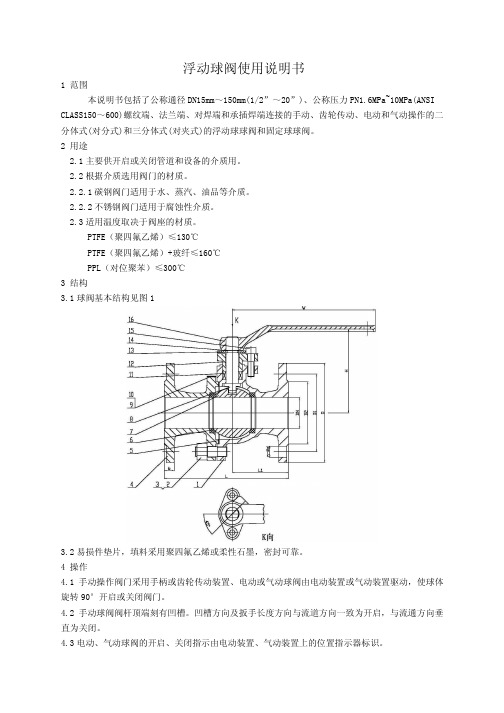
浮动球阀使用说明书1 范围本说明书包括了公称通径DN15mm~150mm(1/2”~20”)、公称压力PN1.6MPa~10MPa(ANSI CLASS150~600)螺纹端、法兰端、对焊端和承插焊端连接的手动、齿轮传动、电动和气动操作的二分体式(对分式)和三分体式(对夹式)的浮动球球阀和固定球球阀。
2 用途2.1主要供开启或关闭管道和设备的介质用。
2.2根据介质选用阀门的材质。
2.2.1碳钢阀门适用于水、蒸汽、油品等介质。
2.2.2不锈钢阀门适用于腐蚀性介质。
2.3适用温度取决于阀座的材质。
PTFE(聚四氟乙烯)≤130℃PTFE(聚四氟乙烯)+玻纤≤160℃PPL(对位聚苯)≤300℃3 结构3.1球阀基本结构见图13.2易损件垫片,填料采用聚四氟乙烯或柔性石墨,密封可靠。
4 操作4.1手动操作阀门采用手柄或齿轮传动装置、电动或气动球阀由电动装置或气动装置驱动,使球体旋转90°开启或关闭阀门。
4.2手动球阀阀杆顶端刻有凹槽。
凹槽方向及扳手长度方向与流道方向一致为开启,与流通方向垂直为关闭。
4.3电动、气动球阀的开启、关闭指示由电动装置、气动装置上的位置指示器标识。
5 保管、保养、安装和使用5.1阀门应存放在干燥,通风的室内,阀门通道两端应堵塞。
5.2长期存放的阀门应定期检查,清除污物。
应特别注意密封面的清洁,防密封面的损坏。
5.3安装前应仔细核对阀门标志是否与使用要求相符。
5.4安装前应检查阀门通道和密封面,如有污垢,应使用清洁布擦拭干净。
5.5安装前检查填料是否压紧,应确保填料的密封性,同时不应妨碍阀杆的转动。
5.6安装后系统或管路试压时,阀门必须处于全开位置。
5.7使用中应将球体全开或关闭,不应将球体部分开启做调节流量用。
5.8手动阀门在开启或关闭操作时,应使用手柄开、关,不得借用辅助杠杆或其它工具。
5.9阀门使用应定期检查,检查密封面有无磨损及垫片填料。
若损坏失效,应及时修理或更换。
- 1、下载文档前请自行甄别文档内容的完整性,平台不提供额外的编辑、内容补充、找答案等附加服务。
- 2、"仅部分预览"的文档,不可在线预览部分如存在完整性等问题,可反馈申请退款(可完整预览的文档不适用该条件!)。
- 3、如文档侵犯您的权益,请联系客服反馈,我们会尽快为您处理(人工客服工作时间:9:00-18:30)。
SUNGO VALVES GROUP CO.丄TD
管线阀门
PIPELINE V ALVE
浮动球阀使用说明书
FLOATING BALL VALVE OPERATING INSTRUCTIONS
Instruction
1、用途和性能规范:Purpose and Specification
本产品是我公司按API 6D/API 608设计、制造的钢制管线浮动球阀,适用于液体、气体等介质,在管路上作启闭装置,具有密封结构可靠、先进,流阻小,启闭迅速、灵活,使用寿命长,安全可靠,维修方便等优点,可广泛的用于石油、化工、炼制、钢铁、造纸、医药等行业。
This products is our compa ny accord ing to the API 6D/API 608 desig ns and manu factures of steel pipeline floating ball valve, It is used for liquid,gas etc tubing line open or mai n adva ntages in clude: Reliable seali ng structure 、Thech no logy adva need、Small liquid resista nee > Flexible ope n and close、Long service life 、Safe reliabe、Convienient maintance etc. This kind of ball valve is widely utilized in Petroleum、Chemical industry 、refinement 、Steel and iron 、papermaking, medicine etc.
产品性能规范表
Performa nee Specificatio n
2、采用的主要标准:The main adoption standard
设计制造与结构长度按API 6D/API 608 的规定;Design conform to API 6D/API 608
法兰型式及尺寸按ASME的规定;Flange conform to ASME
结构长度按ASME的规定;Face to face conform to ASME
阀门的温度-压力额定值按ASME的规定;Temperature-class conform to ASME
检验和试验按API 6D的规定;Test conform to API 6D
防火标准按API 607/6FA 的规定。
Fire safe conform to API 607/6FA.
3、结构特点:Structure Characteristic
90 度回转,操作扭矩较低,便于实现自动控制。
90 degree rotary, Low operating torque, it is easy to realize automatic control.
全通径,流阻小,便于管线清扫。
Full port, small resistance to liquid, easy to clean the pipeline
阀杆头部的扁方结构提供了安装与管线平行的水平手柄,可防误安装,且容易识别阀门开或关的状态。
Stem head's flat square structure has provided the installment and the pipeline parallel horizontal handle, can prevent wrong installation, and easy to distinguish the condition which the valves open or close.
阀杆下部设计一防飞出结构的整体式凸肩,同时也具有上密封功能,进一步确保了阀杆部位的密封。
The lower end of the stem is designed with an integral collar to be blow out-proof . it also functions as the backseat for assured stem sealing.
阀门上设置的防静电弹簧,确保球体、阀杆和阀体之间电流的连续性,避免静电产生火花引起火灾,保证管线系统安全运行。
An antistatic feature is provided to ensure electrical continuity between ball ,stem and body.
锁定装置可通过填料压盖和限位块上的小孔方便的安装,以防止人为的或意外因素导致阀门误动作。
Facility for mounting a locking device for prevention of accidental valve operation is provided.
一旦发生火灾,阀门的防火结构可使流体的外漏和内漏最小化。
Once has the fi re, Valve ' s fire -safe structure may keep the fluid minimum leakage of outside and in side.
阀体与阀盖中法兰设计为金属一一金属接触形成定止口法兰,以防垫片密封失效引起流体大量泄漏。
Betwee n body &bonnet , the flange ' s desig n is metal --------- the metalic con tact forms fixed spigot flan ge, preve nt gasket seal failure to cause the fluid large amount of leakage
经加工的阀体颈部可方便的安装各类执行机构。
After processed, the body ' s n eck can be in stalled all kinds of actuator.
坚固的阀体足以承受流体的温差压力负荷、管线附加应力及振动。
The solidity body can withstand the fluid ' s pressure load of temperatur e differenee 、pipeli ne additi onal stress and vibrati on.
4、主要零部件材质Ma in parts materials
5、安装、保管和使用Maintenance, Installation and Using
本阀可任意位置安装,但必须要便于维护、检修和操作。
The valve can be installed anywhere, but it must be easy to maintain, repair and operate. 安装前应仔细
核对阀门产品上的标志是否符合现场使用要求。
Before installing,should check the product 's marks whether to meet the field operating requirements.
安装前应检查阀门内腔和密封面,不允许有污物附着,符合安装要求方可安装。
Before installing, should check the valve 's inner cavity and seal surface. Don 't allow any dirt .should meet the installation requirements.
安装前应检查阀门在开或关过程中,是否有卡阻现象、螺栓螺母是否有松动、填料是否压紧等。
Before installing should check the valve in the process of open or closed ,whether there
is the phenomenonof jamming、if the bolt&nut is loosening 、whether the packing is pressed etc.
本阀门产品应存放在干燥通风的室内,两端通道应堵塞,且阀门处于开启位置,不准堆叠。
The valve should be stored ih the dry and well ventilated room, should be blocked at both ends of the passage and the valve should be totally open,don 't allow to stack.
长期存放的阀门应定期检查,清除污物,并在机加工表面涂防锈油脂。
For the long time storage ' s valves ,should be regular inspected , cleared the dirt and
spreaded the anti-corrosive grease on the machined surface.
本阀门产品在管线系统运行中只能全开或全关,不允许作调节用。
In the pipeline system operation, the valve only can open or close, don 't allow to make the adjustment to use.
6、产品结构示意图Product structure diagram
7、可能发生的故障及解决措施:Malfu nctio n& its solution。