AL-238T、2316T说明书
238W说明书

国兴科技GX-238W/GX-2316W 多功能防盗报警控制器目录前言 (3)第一章概述 (3)1.1概况 (3)1.2功能简介 (3)1.3基本配置 (4)1.4主要技术性能指标 (4)第二章安装接线说明 (4)2.1安装接线图 (4)国兴科技GX-238W/2316W有线9-16防区打开、关闭设置 (6)2.2电源的连接 (6)2.3有线探测器的连接 (6)2.4警号的连接 (6)2.5电话线的连接 (6)2.6监听头的连接 (7)2.7键盘的安装 (7)2.8仅用无线防区,不接有线防区的安装(新宏晖DFG--B08J有此功能) (7)第三章系统操作 (7)3.1系统操作 (7)3.2遥控器的日常操作(新宏晖DFG--B08J有此功能) (8)3.3键盘面板及声光指示 (8)3.4布防 (10)3.5撤防:解除警戒状态 (10)3.6远程控制: (10)3.7电话接警控制: (11)3.8录音: (11)3.9消警 (11)3.10旁路防区查询: (11)第四章系统设置 (11)4.1系统出厂基本设置 (11)4.2复位 (12)4.3进入设置状态 (12)4.4退出设置状态 (12)4.5修改安装员密码 (12)4.6修改用户密码 (12)4.7无线探测器的学习(新宏晖DFG--B08J有此功能) (13)4.8无线探测器的删除(新宏晖DFG--B08J有此功能) (13)4.9防区类型及报警声输出设置 (13)4.10用户编号(中心编号)设置: (13)14.11布防延时时间设置 (14)4.12报警延时时间设置 (14)4.13设置报警电话号码 (14)4.14报告传输设置 (14)4.15远程控制打开/关闭 (15)4.16远程遥控振铃声次数设置 (15)4.17接警放录音方式的选择 (15)4.18电话线检测打开/关闭设置 (15)4.19主机中心通讯格式选择设置 (15)4.20可编程4+2代码需手动设置以适应不同的报警中心 (15)4.21主机自检报告时间间隔设置 (16)4.22警号响声时间设置 (16)4.23强制布防设置 (16)4.24布撤防警号响声设置 (16)4.25交流电断电报警设置 (16)4.26键盘防撤开关报警功能打开、关闭设置 (16)4.27键盘断线检测设置 (16)4.28中心精度设置 (16)4.29中心信号时间设置: (16)第五章疑难问题解答 (18)产品的质量保证 (19)安装资料 (19)2前言欢迎您选择使用铁盒国兴科技GX-238W/ 2316W多功能系列报警控制主机来保护您的生命和财产。
易控AI-716 716P型精密人工智能工业调节器 使用说明书

AI-716/716P型精密人工智能工业调节器使用说明书(V8.2) 版权所有(C)1994-2014目 录1 概述 (3)1.1 主要特点 (3)1.2 型号定义 (4)1.3 模块使用 (7)1.3.1 模块插座功能定义 (7)1.3.2 常用模块型号 (8)1.3.3 模块安装更换 (10)1.3.4 模块的电气隔离 (10)1.3.5 部分模块应用说明 (11)1.4 技术规格 (12)1.5 节能与环保的设计 (14)1.5 接线方法 (15)仪表后盖端子排布如图: (15)2 显示及操作 (20)2.1 面板说明 (20)2.2 参数设置流程 (21)2.3 程序设置流程 (22)2.4 操作方法 (23)2.4.1 设置参数 (23)2.4.2 快捷操作功能 (23)3 参数功能 (26)3.1自定义现场参数 (26)3.2完整参数表 (27)3.3 特殊功能补充说明 (37)3.3.1 单相移相触发输出 (37)3.3.4 上电时免除报警功能 (37)3.3.5 通讯功能 (37)3.3.6 温度变送器/程序给定发生器 (38)3.3.7 精细控制 (38)3.3.8 自定义输入规格 (40)4 程序控制(仅适用AI-716P型) (41)4.1 功能及概念 (41)4.2 程序编排 (43)4.2.1 斜率模式 (43)4.2.2 平台模式 (44)4.2.3 设置程序给定值及时间 (45)4.2.4 运行多条曲线时程序的编排方法 (46)1 概述1.1 主要特点●输入可自由选择热电偶、热电阻、电压、电流并可扩充输入及自定义非线性校正表格。
●高精度、低温漂,热电偶冷端除自动补偿外可支持Cu50铜电阻或冰点等高精度补偿模式。
●采用先进的AI人工智能PID调节算法,无超调,具备自整定(AT)功能及全新的精细控制模式。
●采用先进的模块化结构,提供丰富的输出规格,能广泛满足各种应用场合的需要,交货迅速且维护方便。
安利AT03系列PID温度控制器用户手册说明书

2Table of ContentChapter 0OverviewChapter 1SpecificationDetail SpecificationDetail FeaturesOrdering InformationChapter 2InstallationMounting ProcedureTerminalsChapter 3ProgrammingTerminologyPower-up SequenceHierachal Tree MenuDevice HoldDevice LockParameter Flow ChartParameter Description, Range, Initial ValueExamplesChapter 4InputChapter 5OutputChapter 6AlarmAlarm TypeAlarm ModeChapter 7CommunicationSample CommandsParameters and AddressesAppendix A Error Code3Chapter 0 : OverviewANLY AT03 series is an 1 input, 2 output, 3 alarm, auto-tuning PID temperature controller designed to accommodate comprehensive needs in process automation and system integration.Wide ranges of inputs are accepted, including thermocouple (T/C: type K, J, T, R, E, S, B, N), Resistive Temperature Device (RTD: Pt100, JPt100) and linear input (voltage, current). Up to 2 output controls include relay, SSR, linear voltage, linear current and signal retransmission. Servo motor control is also possible. Up to 3 alarms are available and each has different functions and modes for cus-tomizations. This controller can have up to 8 segments for a single process.A separate optionsl channel allows Remote Set Point via linear voltage or linear current. The same channel can also be used for current transformer for heater break alarm. The users may chose between RS-232 and RS-485 communication modules for links up with computer for programming.4Chapter 1 : SpecificationDetaile Information5Ordering InformationANLY AT03 can be customized to specific needs and requirements.The ordering code consists of a 10-digit numeral in 3-4-3 format :A T - 0 3 - -“03” is the designation for AT03 series controllers. The followingexplains the representation of the remaining 8 numerals.6The dimension size is a meas-urement for the device face plate. Note that AT-402 is verti-cal while AT-603 is horizontal, although they have the same DIN size.1 is for both thermocouple and RTD sensor inputs. However, the sensor type also needs tobe specificied by users under Level menu. 2 through 9 are for linear inputs.71 alarm is standard on all AT03.There can be upt o 3 alarmson AT-403, AT-603, AT-703 andAT-903. However, AT-503 canonly have up to 2 alarms.A relay output on Ouput 1 isstandard on all AT03. It canbe changed to any of the 9types. Note that motor controlon Output 1 uses 3 terminals.Therefore, Motor Control optionis not available with Output 2.Therefore, “90” is the code formotor controlo output.8In Other option, there can be inputs for DC24V, current trans-former and Remote Set Point (R-SP). Current transformer is used as the heater break alarm. R-SP is used to change SV remotely with volatage or cur-rent. AT-403 is availiable with Other option but this will negate Ouput2.Communication module, such as RS-232 and RS-485 module, is availiable for direct link up with PC for programming.Program is the option thatgives the controller segment programming.9Some models, due to their limited terminals, cannot be ordered with all the features. Such limitations are:Chapter 2 : InstallationAT-503 is not available with the Other and the 3alarms options. Also, AT503 only uses two terminals for its RS-485 communication while others use three terminalsServo motor control option occupies one Output 2 terminal. Hence, the Motor Control and Output 2 are not available on the same device.An example of order code is AT – 903 – 1111 – 000. It would have 1/4 DIN size, a sensor input, 2 relay outputs, 1 alarm, no Other option, no Communication option and no Program Control optionsDevice MeasurementPanel Cutout Measurement Type A B C D E a b c d AT-403489610.5839046+0.591+0.512070AT-503484810.5834546+0.546+0.57070AT-603964810.5834391+0.546+0.570120AT-703727210.5836768+0.568+0.5100100AT-903969610.5839091+0.591+0.5120120All measurements in millimeter (mm )10Mounting ProcedureMake sure the front panel is no more than 10mm thick. Also, each of the two brackets needs additional 6mm clearance outside of the shell casing on each side.Make a panel cut-out precise to the measurement according to the type. (see the table on the previous page)Insert the controller into the cutout from the front side of the panelAlign the bracket so the notches are in their slots and the wide side towards the front panel.Pinch the prongs and slide the bracket forward till the bracket is firmly against the backside of the front panel.Repeat step 3 through 5 with another bracket on the other side.1.2.3.4.5.6.TerminalsFor wire terminations, the recommended terminals are fork or ring terminals with #6 stud size, narrow tongue, and with insulation. Wiregauge should be at least AWG 18.^6The terminal layout for different models are as followed.50/60 Hz OUT1TransmissionOUT1TransmissionAT-703AT-503AT-403 / AT-603 / AT-903OUT150/60 Hz INPUTTransmission Of all 5 types of ANLY AT03, there are 3 styles of terminal arrange-ments. AT-503 has 14 usable terminals; AT-403/603/903 have 19 usable terminals; AT-703 has 18 usable terminals. Each terminal has numbering on the edge of the casing for easy identification.Chapter 3 : ProgrammingTerminologyProcess value display Set value displayAT OP1AL3AL2AL110%100%Auto tuning indicatorControl output 2, 1 indicatorAlarm output 3, 2, 1 indicatorManual mode indicator Programmable mode indicator Ramping mode indicatorSoaking mode indicator Manipulated output displaySegment-in-process display PRG MANPV SVRP SK1 ~ 8~Press-and-Holdpress a key and hold it untill the display has changedPress-and-Releasepress a key and release it immediatelyMenu modea heirarchal tree menu with the PV display showing the menu title and the SV display showing the submenu or the parameter.Adjust modewhen the value at the SV diaply is flashing and ready to be adjusted with the down or up button.Standby modewhen the red PV display is sowing the temperature’s present value and the SV display is showing the set value. At this mode, the controller can ne changed to Menu mode or Operation mode.Operation modewhen the device is runningSet Keyused to navigate within the hierachal set-up menu Shift Keyused to shift in and out of the adjust modeDown Keyused to decrease a value or to scroll down. When not in programming mode, press-and-hold to call up lock or hold function.Up Keyused to increase a value or to scroll up.When not in programming mode, press-and-hold to go backto the standby display.Power-up SequenceWhen the controller is powered up, it goes through 4 diagnostic stages.1st stage: All displays light up. Users can verify that alldisplay LEDs are functional.2nd stage: The PV display shows Input1 and the SVdisplay shows the temperature unit used, C. for Celsiusand F. for Fahrenheit. Following the unit is the sensortype and range.3rd stage: The displays show the range of temperatureaccording to the chosen sensor type and range. PV displayshows the minimum and the SV display shows the maximum4th stage: The controller goes to the standby modeand the device is operational.Hierarchal Tree MenuANLY AT03 has a hierarchal tree menu to organize the parameters and functions. There are 7 Submenus under Level.When not in the adjust mode, press-and-hold Set or Up will always bring the device to Standby mode.User (uSEr) submenuControl (CntL) submenuOutput (Out) submenuInput (inP) submenuProgram (ProG) submenuHide (HidE) submenuSpecial Control (SPC) submenuDevice HoldIn Standby mode, press-and-hold Down to enter Hold mode. In the Hold mode, the SV display will be flashing HoLd, meaning all opera-tion has been suspended.Device LockUnder Level menu, press-and-hold Down to enter the lock param-eter submenu. The parameter is freely adjustable from 0 to 9999.However, only 10 numbers will lock the device in specific ways.The following table details the number and the corresponding table function.Parameter Description, Range, Initial ValueAtOutLManAL1SPVSVAL1LAL1uAL2SAL3SSoAKrAmP“SoAK” only performs when AL1M is set at 8 or 9, and the control-ler is without program function. If AL1M is set at 8, AL1 will shift to soak function and the contact is normally open; if AL1M is set at 9, AL1 will shift to soak function and the contaact is normally closed.AL2LAL2uAL2LAL2u“rAmP” sets the rate of change for PV when the controller is without program function. For example, if ramp is set at 10, the PV will increase 10 degree per minute. However, if PV is higher than SV, the PV will decrease 10 degree per minute.PVoFIf PV is not correct to SV, PV can be offset linearly with positive or negative pvof .If PV is not correct to SV, PV can be adjusted with “pvrr”. The formula is:PV (now) - PV (pre) * pvrr + pvofPVrrSVoFIf SV is not correct to PV, SV can be offset linearly with positive ornegative “SVoF” .Ct“Ct” is used to detect if the heater is broken. The value ranges from 0.0A ~ 100.0A. (“Ct” is only availiabe if the option is ordered)PVrr > 1PVrr < 1PVHbA“Hba” ranges from 0.1A ~ 100.0A. For example, when the control output is on and “Ct” <= “Hba”, the heater is broken. The alarm is triggered. Or when the control output is off and “Ct” >= “Hba”, the alarm is then triggered. (“Hba” is only availiabe if the option isordered)LbAParameters for Loop break Alarm. For example, when out1 = 0.0% and “lba” has elapsed, PV should be below “lbd”. If PV is till within “lbd”, the alarm is triggered. When out1 = 100% and “lba” time has elapsed, PV should be higher than “lbd”. if PV is till within “lbd”, the alarm is triggered. (“lba” and “lbd” is implemented through firmwareonly)LbdrPtm“rptm” displays how many times the program has repeated thus far. This parameter only works whenthe controller has program function turned on.AtoFP1i1d1Ct1HSt1“ct1” is the cycle time for output 1. Normally, it is set at 0 for 4~20mA output, 1 for SSR output and 15 for relay output.ArP2i2d2Ct2HSt2“Ar” is for preventing over-shooting. This parameter sets an integral delay. The setting ranges from 0 ~ 100%. At 100%, the integral will perform when PV reaches the propotional band. At 50%, the inte-gral will perform when PV reaches 50% of the propotional band.SSV“SSV” is used to prevent the heating system temperature rising too quickly at the start. For example, to achieve 120 degree slowly, “SSV” is set at 120.Sout“Sout” sets the output percentage when PV is under “SSV”.Stme“Stme” sets the time interval when the soft start is deemed failed. When the “Stme” time is reached and the PV has not reached“SSV”, the soft start has failed and the controller will revert to SV.ruCy“ruCy” sets the running cycle time in motor valve control, the time from close to open or from opento close.STMESTME0%100%SSV SVSSV SV0%100%Motor ValverPt“rPt” set the number of times the program will repeat execution.StAt“StAt” sets the start mode the program. “CoLd” requires manual start. “rSET” starts the program automatically after the power isturned on. “Hot” starts from memory after a power failure.PVStwAit“wAit” sets the time the SV will wait for PV if PV chanes slower than SV.“Pid” selects between PID (Pid) and Level PID (LPid). Level PID allows upto 4 level of different PID.PidEndPAL1FAL1HAL1t“EndP” controls the the flow of the program to be continuous (Cont) or 1-program-only-and-stop (StoP).Please refer to Chapter 6 : Alarm for functio descriptionsAL1MPlease refer to Chapter 6 : Alarm for mode descriptionsActOutmO1LSAOO1HSPlease refer to Chapter 5 : Output for mode descriptionsAL2F AL3F AL2H AL2t AL1M AL3H AL3tAL3MO2HSO2LSt1SSt1On“t1SS” sets the segment the alarm will be activated. For example, if the alarm activation is desired in Segment 2, set “t1SS” at 2.“t1On” sets the time the alarm will be activated. For example, if the alarm activation is desired after 3 minute in Segment 2, set “t1On” at 3min and “t1SS” at 2. Note that the Program Time in Segment 2 (tP2) may be longer than 3 minute.t1ESt2SSinP1LoSPt2oFt2ESt2Ont1oF“t1oF” sets the time the alarm will be deactivaed. For example, if the alarm deactivation is desired after 7 minute in Segment 6, set “t1oF” at 7min and “t1ES” at 6. Note that the Program Time in Seg-ment 6 may be longer than 7 minute.“t1es” sets the segment the alarm will be deactivaed. For example, if the alarm deactivation is dersired in Segment 6, set “t1ES” at 6.LoAnHiSPA1LSHiAnunitA1HSdPbAudAddrFiLtinP2A2LSA2HSLEV1LEV2LEV3LVSLLevel PID Selection Monitor selects whiche level of PID to bemonitored. For example, if Level3 parameters (L3P1, L3P1, L3d1...etc.) are to be monitored, set “LVSL” to 3. Note that PID parameterunder CONTROL submenu needs to set at Level PID (LPiD).L1P1L1i1L1i2L1d1L1ArL1P2L2P1L2i1L2d1L2Ar L2P2L2i2L2d2L3P1L3i1L3d1L3Ar L3P2L3i2L3d2L4P1L4i1L4d1L4ArL4P2L4i2L4d2SEGtiMESV1tP1EndStS1SV2tP2tS2SV6tP6tS6SV3tP3tS3SV4tP4tS4SV5tP5tS5SV7tP7tS7SV8tP8tS8~~~SV1SV2SV3SV4SV5tP1tP2tP3tP4tP5tS1tS2tS3tS4tS5EndS = 5A. Example : How to set “SV” at 200O CB. Example : How to set AL1S at 20O CwindowsC. Example : How to set “AT” (auto tuning)D. Example : How to enter different “level” for setting parameter windows(1) Enter “CntL” level(under PV/SV initial window)SV window (under PV show “LEVL”this levelwindow eters in this level window(2) Enter “Out” levelwindow (under PV/SV initial window)(under PV show “LEVL”levelin this level window41(3) Enter “inP” levelwindow (under PV/SV initial windows)(under PV “LEVL”)levelwindowin this levelwindowlevelwindow (under PV/SV initial window)(under PV show “LEVL”)42windowin this level window (5) Enter program levelwindow (under PV/SV initial window)(under PV show “LEVL”)window, this parameter only display executing segment eters, this parameter only display time for ramp or soak stepswindow43The operation from SV2 to SV8are the same as SV1segment(6) Enter “Hide” levelwindow (under PC/SV initial window)(under PV show “LEVL”)In this level, the user can arrange parameter order or hiding from No. 1-2 to 1-22, 2-14 to 2-17 and 3-20 to 3-27 (please refer to level parameter flow chart), but same parameter can not be arranged in 2 positions at the same time. For example, to arrange “OUTL” to 1-3 you need to cancel it in 1-2 first. When canceling or to hide, select “non” on the “SV”44E. Example : How to set “LOCK” functionat this level windowwill display that parameter.The operation in 1-2 to 1-22, 2-14 to 2-17 and 3-20 to3-27 are all the same.window (under PV/SVinitial window)window4546Chapter 4 : InputAT03 series is designed to accept thermocouples sensor, RTDsensors, linear voltage and linear current inputs. The input type is specified partly through hardware and needs to be specified at the time of ordering.For sensor inputs (thermocouple and RTD), AT03 can accept K, J, T, R, E, S, B, N or N type thermocouple and Pt100 or JPt100 RTD sensors. There are different segments in firmware to optimize the sensing performance. The specific segment is specified throughfirmware and is specified through the parameter inP1 under inpsubmenu.For linear input, all vairotions are soecified through hardware at the time of ordering.4748Chapter 5 : OutputAT03 series has highly customizable outputs for customers’ specific needs. It may have upto 2 control outputs. The desired ouputsneeds to be specified at the time of ordereing and set by the users under OUTPUT submenu according to the hardware.Output hardware ordering information49Chapter 6 : AlarmAT03 models can have upto 3 alarms. Each alarm can be programmed to different function and different mode.Alarm Function50。
(整理)2316安装手册.
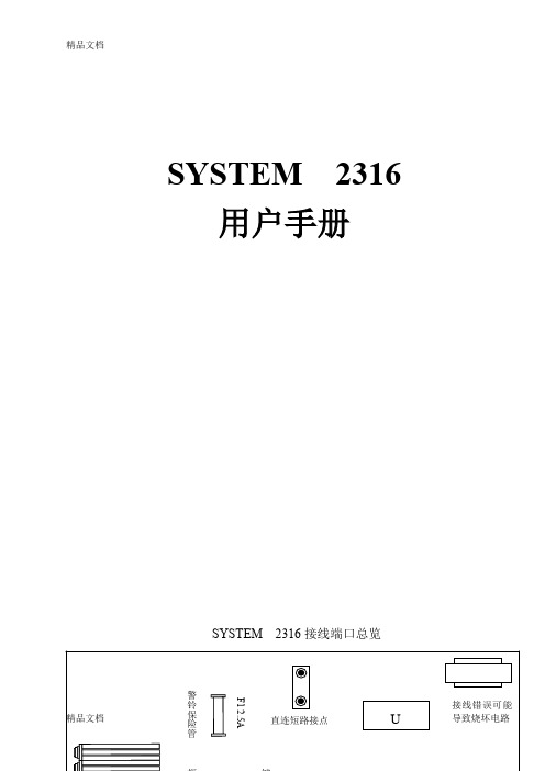
SYSTEM 2316 用户手册前 言介绍SYSTEM2316是一种16防区可编程控制主机。
根据不同的需要,SYSTEM2316既可作为本地型主机使用,又可作为联网型主机投入运作。
具体采用何种工作模式,由编程决定。
该主机的编程方式亦很灵活:既能通过Alpha键盘或LED键盘进行编程,也可以通过指挥者2000/监察者2000软件进行遥控编程。
本手册覆盖范围本手册所介绍的是SYSTEM2316控制主机安装与编程的基本方法,有关遥控编程的内容请参见指挥者2000/监察者2000软件的用户手册。
主机安装安装SYSTEM2316应该装在便于接入交流电源、电话线和地线的位置处。
●从机箱上拆下电路板,以防止在敲击预制孔时损坏电路板。
●敲开机箱上的预制孔。
●在墙面上标出安装螺丝的孔位。
●在墙面上固定住机箱,将电缆穿过预制孔。
错误!未找到引用源。
装入电路板,注意在电路板的左下角接上地线焊片。
●再将接线片连接到机箱门下部合页处,使箱门接地。
接地为保证瞬时放电保护电路能正常工作,控制主机必须接地。
理想的地线应是电源线路、电话系统和防盗系统的公共地线,这种地线形式称为“统一接地”,保护性能最佳。
将与主机箱体相连的那根绿色导线接到接地棒、自来水管或其他接地装置上,即可实现主机箱体的接地。
主机接线备用电池☆备用电池SYSTEM2316配用的电池是12V,6.5AH密封铅酸电池(C&K1265)。
禁止使用非充电型或非密封铅酸型电池。
建议每隔3-5年更换一次备用电池。
将红色导线接到电池的正极,黑色导线接到电池的负极。
保险管F4备用电池由保险管F4(3A,3AG,速熔型)提供防反接保护。
☆交流电源端口(端子①和②)交流电源由一只16.5V AC,25-40V A,50/60HZ的变压器(UL标准2级)提供。
将变压器的初级直接接入交流供电线路,次级连接到端子①和②。
为减少压降至少应使用18AWG(直径1.02㎜)的导线进行连接。
238c使用指南
七、修改密码若您想要改密码,并使原密码作废,改法如下:236/2316主机:原密码*0#1# 新密码# 新密码#*#,新密码为任意4位数。
238主机:原密码*0# 新密码# 新密码#*#。
新密码必须是开头为1的2~5位数。
八、指示灯的含义及故障判别POWER:电源灯,表示交流电供电正常ARM:布防灯,表示系统处于布防状态READY:表示防区都处于正常状态,可以布防SERVICE:故障灯,具体含义见下表。
故障灯亮时不影响主机正常使用。
现象原因解决方法1、SERVICE灯常亮自检故障、交流电曾经断电键入密码*68#保险管断更换保险管,后键入密码*68#2、SERVICE灯快闪通讯失败236、238如1操作,2316必须与中心通讯正常一次后,SERVICE灯才熄灭3、SERVICE灯常亮,POWER灯闪烁,电池电压低键入密码*64#,5分钟后键入密码*68#。
如上操作后,若还不能解决,说明电池已报废。
更换电池,充电48小时后再重复上述操作。
4、SERVICE灯慢闪看门狗故障键入密码*68#5、SERVICE灯常亮,某一防区灯闪烁该防区编为监视回路,并且该回路断路,认为回路故障,查该回路某一处已断路,维修后键入密码*68#6 、2316键盘每隔约1分钟“嘀”一声电池电压低、防区故障、通讯失败等找到故障原因,排除后,键入密码*68#236、238、2316常见报警主机故障及处理Q1: 236、238、2316键盘无任何显示按键无反应A: (1).主机的1、2端子是否有交流16.5伏电压?键盘电源端子是否有12伏直流电压?如果检查16.5伏电压不正常可能是220伏交流电源或变压器损坏,检查更换使其供电正常。
如果主机上没有直流12伏电压先检查键盘保险丝是否烧断,如烧断查明原因更换新的(236-F2 0.5A;238、2316-F3 0.75A)。
更换保险丝后仍没有直流12伏电压或电压不正常需找到直接供货商送修处理。
新波电子产品介绍书说明书

UMR SeriesPrecision, Double-Row BallBearing Linear StagesShown with optional M-PBN Base Plate. Order actuators and base plates separately.UMR Series Linear Stages feature steel construction for high stability and rigidity . The ball bearings and precision-ground bearing surfaces provideexceptional linear travel, with angular deviation better than 100-200 µrad. UMR3,UMR5, and URM8 Series stages have double-row ball bearings making them an excellent choice for carrying high loads. UMR12 Series stages contain a single row of ball bearings. In all UMR stages, the moving carriage is preloaded by two springs to ensure constant micrometer contact for smooth, backlash-free motion.Four stage sizes, each available in several travel ranges , allow you to closely match both your physical and performance requirements. UMR5, UMR8, and UMR12 have aperture versions available with a clear hole through the carrier and stage body. Apertures are very useful for positioning of optics, fiber optics,or cabled devices.M-UMR12.4AM-UMR8.51AM-UMR8.25AM-UMR5.25AM-UMR5.16AUMR stages are available with clear apertures for demanding applications. Actuators sold separately.Key Features•0.16–3.15 in. (4–80 mm) of travel •Low-profile design•Steel construction for high stability and rigidity•Double-row ball bearings for higher load capacity (except UMR12)•Angular deviation better than 100–200 µrad•Threaded micrometer mountingMultiple drive options cover the range of precision positioning. Standard BM Series micrometers provide 1 µm sensitivity, while BD Series differential micrometers offer 0.1 µm. For ‘set, lock, and leave’ applications a fixedpositioning kit replaces the micrometer with two opposing adjustment screws and lock nuts. An optional carriage locking kit includes a screw that mounts in the stage body opposite the micrometer. Motorized or electrostrictive actuators can be added for precision motion control.Generous hole patterns allow great flexibility in component placement on the stage mounting surface. Two stages can be easily stacked in an XY configuration and mounted to a table or breadboard (M-PBN mounting base required, except UMR8 and UMR12). Multi-axis stage configurations are easily assembled using EQ Series angle brackets. UMR stages are compatible with UTR and URM rotation stages, BGM goniometers, and SL and SK mirror mounts.SpecificationsUMR3.5 (M-UMR3.5)UMR5.16 (M-UMR5.16)UMR5.25 (M-UMR5.25)UMR8.25 (M-UMR8.25)UMR8.51 (M-UMR8.51)UMR12.40 (M-UMR12.40)UMR12.63 (M-UMR12.63)UMR12.80 (M-UMR12.80)Two UMR5.25 stages with a UTR rotation stage.Model (Metric)Angular Deviation(µrad)Load Capacity [lb (N)]UMR3 (M-UMR3)<100135 (600)UMR5 (M-UMR5)<200135 (600)UMR8 (M-UMR8)<200202 (900)UMR12 (M-UMR12)<20090 (400)Load CharacteristicsRelated Products•M-PBN Base Plates •UTR Rotation Stages•EQ Series Angle BracketsMounting Bridles aid in constructing complex systems (see the Accessories Section).Multi-axis stage configurations are easily assembled using UMR stages and EQ Series angle brackets.Q Off-center load, Q ≤Cz/(1 + D/a)Cz Centered normal load capacity D Cantilever distance in mm a Bearing constant-Cx Axial load capacity in the direction toward the actuator+Cx Axial load capacity in the direction away from the actuator ωDrive torque for +Cx = 10 N k αx Angular stiffness (roll)k αy Longitudinal stiffness (pitch)k αzTransverse stiffness (yaw)Model (Metric)Cz (N)+Cx (N)-Cx (BM)(N)-Cx (DM)(N)a (mm)ω(Nm)K αx (mrad/Nm)K αy (mrad/Nm)K αz (mrad/Nm)UMR3.5 (M-UMR3.5)600104030200.040.70.30.5UMR5.5 (M-UMR5.5)600124030220.050.10.20.2UMR5.16 (M-UMR5.16)600154030220.050.10.20.2UMR5.25 (M-UMR5.25)600114030220.050.10.20.2UMR8.4 (M-UMR8.4)9001810050400.070.050.050.05UMR8.25 (M-UMR8.25)9001710050400.070.050.050.05UMR8.51 (M-UMR8.51)90011100400.070.050.050.05UMR12.40 (M-UMR12.40)40035450700.080.020.020.02UMR12.63 (M-UMR12.63)40025450700.080.020.020.02UMR12.80 (M-UMR12.80)40020450700.080.020.020.02Whatever size you need, Newport has a stage for your application.Ordering InformationActuators must be ordered separately, please see below for specificActuator/Stage combinations. Please see the Manual Actuators Section for detailed information.* For 40 nm minimum incremental motion, this stage is compatible with the AD-30 when used with a motorized actuator adaptor as listed below.✝Motorized actuators require an adaptor for mounting on UMR stages. Order one adaptor from the list below for each motor and stage used.For UMR8, use ADAPT-BM17-375For UMR12, use ADAPT-BM25-375‡For fixed positioning applications, order 2 each of the corresponding carriage locks.For Vacuum Compatibleversions (50% price premium at time of order), append “V6” to the part number (eg. UMR3.5V6).Two UMR stages with an SL optical mount.Model (Metric)Travel [in.(mm)]Actuator Sensitivity Motorized Actuator FixedPositioning Kit Carriage LockBase Plate1 µm0.1 µmUMR3 SeriesUMR3.5 (M-UMR3.5)0.20 (5)BM11.5DM11-5FP3-5CL3-5M-PBN3UMR5 SeriesUMR5.5 (M-UMR5.5)0.20 (5)BM11.5DM11-5‡CL6-5M-PBN5UMR5.16 (M-UMR5.16)0.63 (16)BM11.16DM11-16‡CL6-16M-PBN5UMR5.16A (M-UMR5.16A)0.63 (16)UMR5.25 (M-UMR5.25)0.98 (25)BM11.25DM11-25‡CL6-25M-PBN5UMR5.25A (M-UMR5.25A)0.98 (25)UMR8 SeriesUMR8.4 (M-UMR8.4)0.16 (4)BM17.04N DM17-4*‡CL12-4M-PBN8UMR8.25 (M-UMR8.25)0.98 (25)BM17.25DM17-25LTA Series ✝‡CL12-25M-PBN8UMR8.25A (M-UMR8.25A)0.98 (25)UMR8.51 (M-UMR8.51) 2.01 (51)BM17.51LTA Series ✝‡CL12-51M-PBN8UMR8.51A (M-UMR8.51A) 2.01 (51)UMR12 SeriesUMR12.40 (M-UMR12.40) 1.57 (40)BM25.40LTA Series ✝FP18-40CL18-40M-PBN12UMR12.40A (M-UMR12.40A) 1.57 (40)UMR12.63 (M-UMR12.63) 2.48 (63)BM25.63FP18-63CL18-63M-PBN12UMR12.80 (M-UMR12.80)3.15 (80)BM32.80FP22-80CL22-80M-PBN12Model UMR3.52 HOLES,C ’BORED FOR THD A CLR,UMR5 SeriesE SPACING(UMR 5.5/5.16 ONLY)THD A CLR, .79 (20)BOTH SIDESUMR5A Series2 holes, M3 thd, B spacing.Model UMR8.4/8.251.34 (34)THD,ThreadDimension [in. (mm)]Model (Metric)A B C UMR3.5 (M-UMR3.5)4-40 (M3)8-32 (M4)0.500 (12.5)Thread Dimension [in. (mm)]Model (Metric)A B C D EFG H UMR5.5 (M-UMR5.5)4-40 (M3)8-32 (M4)1/4-20 (M6)0.500 (12.5) 1.000 (25.0) 2.000 (50.0) 1.77 (45) 2.28 (58)UMR5.16 (M-UMR5.16)4-40 (M3)8-32 (M4)1/4-20 (M6)0.500 (12.5) 1.000 (25.0) 2.000 (50.0) 1.26 (32) 2.28 (58)UMR5.25 (M-UMR5.25)4-40 (M3)8-32 (M4)1/4-20 (M6)0.500 (12.5)1.000 (25.0)2.000 (50.0)1.26 (32)2.68 (68)Thread Dimension [in. (mm)]Model (Metric)A B C D EUMR5.16A (M-UMR5.16A)8-32 (M4) 1.000 (25.0) 2.000 (50.0) 2.283 (58.0) 1.181 (30.0)UMR5.25A (M-UMR5.25A)8-32 (M4)1.000 (25.0)2.000 (50.0)2.677 (68.0)1.535 (39.0)Model UMR8.51UMR8A SeriesThreadDimension [in. (mm)]Model (Metric)A B C D E UMR8.4 (M-UMR8.4)8-32 (M4)1/4-20 (M6) 1.000 (25.0) 3.000 (75.0) 2.52 (64)UMR8.25 (M-UMR8.25)8-32 (M4)1/4-20 (M6) 1.000 (25.0) 3.000 (75.0)2.09 (53)UMR8.51 (M-UMR8.51)8-32 (M4)1/4-20 (M6)1.000 (25.0)3.000 (75.0)Thread Dimension [in. (mm)]Model (Metric)A B C D E F G UMR8.25A (M-UMR8.25A)1/4-20 (M6) 1.000 (25.0) 2.000 (50.0) 3.000 (75.0) 4.000 (100.0) 3.622 (92.0) 2.087 (53.0)UMR8.51A (M-UMR8.51A)1/4-20 (M6)1.000 (25.0)2.000 (50.0)3.000 (75.0)4.000 (100.0)4.646 (118.0)3.110 (79.0)UMR12 Series1.89 (48)THD B CLR, D SPACINGModel UMR12.40AModel ADAPT-BM17-375Model ADAPT-BM25-375See our website for CAD filesCADThread Dimension [in. (mm)]Model (Metric)A B C D E FUMR12.40 (M-UMR12.40)10-24 (M5)1/4-20 (M6)M18 x 1 1.000 (25.0) 5.65 (143.5)UMR12.63 (M-UMR12.63)10-24 (M5)1/4-20 (M6)M18 x 1 1.000 (25.0) 6.56 (166.5)UMR12.80 (M-UMR12.80)10-24 (M5)1/4-20 (M6)M22 x 11.000 (25.0)8.29 (210.5)1.38 (35)ThreadDimension [in. (mm)]Model (Metric)A B CUMR12.40A (M-UMR12.40A)1/4-20 (M6)10-24 (M5) 1.000 (25.0)。
PCI2316继电器采集卡硬件使用说明书

PCI2316光隔离开关量输出卡硬件使用说明书阿尔泰科技发展有限公司产品研发部修订阿尔泰科技发展有限公司目录第一章功能概述 (2)第一节、产品应用 (2)第二节性能指标 (2)第二节其他指标 (2)第三节、板卡尺寸 (2)第四节、产品安装核对表 (2)第五节、安装指导 (2)第二章安装说明 (3)第一节、PCI2316的布局 (3)PCI2316的布局参见附录4。
(3)第二节、用户连接器 (4)第三章地址空间分配 (8)第一节、I/O地址空间的结构 (8)第四章产品的应用注意事项、保修 (9)第一节、注意事项 (9)第二节、保修 (9)PCI2316继电器采集卡硬件使用说明书版本:V6.00.02第一章功能概述第一节、产品应用PCI2316是一块64路光电隔离开关量输出板。
它的主要应用场合为:◆工业控制第二节性能指标◆通道数:64路输出(光电隔离)◆隔离电压:大于等于1000Vdc◆输出信号最高切换频率10kHz(方波)◆数字输出与PC机完全隔离,隔离耐压>1000Vdc◆PCI总线接口,接口芯片为PLX9052。
◆用户接口:37芯D型插头、40芯插头;◆OC输出(集电极开路输出)。
◆OC输出指输出为无源下拉形式,即输出在高电平时表现为输出为高内阻状态。
◆低电平时输出对地线为低内阻状态(近似对地短路)。
◆输出建立时间小于100微秒◆最大输出电流:大于15mA/路(压降小于1V)◆可以直接驱动PCI2603大功率继电器端子板第二节其他指标◆用户接口:37芯D型插头、40芯双排插头◆工作温度:0℃~50℃◆储存温度:-10~70℃◆相对湿度:-5%~95%◆电源:+5V第三节、板卡尺寸◆板卡尺寸:169mm X92mm第四节、产品安装核对表打开PCI2316板卡包装后,你将会发现如下物品:1、PCI2316板卡一个2、ART软件光盘一张,该光盘包括如下内容:a)本公司所有产品驱动程序,用户可在PCI目录下找到PCI2316驱动程序;b)用户手册(pdf格式电子文档);第五节、安装指导一、硬件安装指导在硬件安装前首先关闭系统电源,待板卡固定后开机,开机后系统会自动弹出硬件安装向导,用户可选择系统自动安装或手动安装。
ck236-ck238-ck2316-报警主机编程简易说明

ck236-ck238-ck2316-报警主机编程简易说明CK2300(CK236 CK238 CK2316)系列主机简要安装及操作手册神州太讯供应CK 系列报警主机-------网址: 北京沈阳济南深圳香港有分公司CK2300主机简要操作使用说明该说明书只是一个简单的操作使用指南,与随机的说明书配套使用,用户请务必详阅说明书,由于编译水平有限,冲突的地方以说明书为准~~~一、名词解释电子防盗报警系统是通过电子探测技术判断非法入侵行为,然后自动将警情传送到报警中心或通过某些设备告知人们的电子设备系统。
探测器是该系统的输入部分,报警系统是根据探测器的动作来工作的。
各种不同类型的探测器用不同手段探测各种入侵行为,如:人体移动,玻璃破碎,门窗开关等等,系统将获得的信号进行逻辑判断,发出警报。
报警主机就象人的大脑一样,是系统的处理部分。
主机将探测器发出的信号按防区类型与主机的工作状态(布防/撤防)作出逻辑分析进而发出警报。
1、各种探测器工作原理简介如下:双鉴探测器:红外+微波被动红外探测器的原理是人体表面温度与周围环境温度存在差别,人体在移动时,这种差别产生的变化通过红外敏感元件检测,从而触发报警。
为了防止误报,被动红外探测器通过菲涅尔透镜将探测覆盖范围分成一定数量的探测区,当温度变化在两个区之间产生时,探测器电路就触发一个信号脉冲,探测器根据信号脉冲触发报警输出。
因此为了防止空气流动或小老鼠等引起的误报,可以设置“脉冲计数”方式:即只有当探测到连续的两个或以上的脉冲才触发报警。
利用微波的多谱勒效应,探测器主动发射微波,在物体上反射回来,若物体是静止的则反射频率不变;若物体是移动的则反射频率变化;探测器电路作出判断而后报警。
双鉴是只有当红外与微波都产生信号才触发一次报警。
门磁开关的主要原理是磁簧开关在磁场范围内保持吸合,离开则触发报警。
玻璃破碎探测器的原理:分析玻璃破碎产生的高频声波及低频振动信号,与内存信号进行比较,从而作出判断。
- 1、下载文档前请自行甄别文档内容的完整性,平台不提供额外的编辑、内容补充、找答案等附加服务。
- 2、"仅部分预览"的文档,不可在线预览部分如存在完整性等问题,可反馈申请退款(可完整预览的文档不适用该条件!)。
- 3、如文档侵犯您的权益,请联系客服反馈,我们会尽快为您处理(人工客服工作时间:9:00-18:30)。
目录前言 (1)第一章:概述 (2)第二章:安装 (3)一.系统方框图 (3)二.系统安装 (3)三.技术参数 (4)四.接线图 (5)第三章:编程设置 (6)一.编程键盘显示及编程命令 (6)二.编程项目 (7)三.编程指南 (8)第四章:附录 (20)一.故障排除指南 (20)二.防区编程记录表 (21)前言感谢您选用我公司的防盗报警控制主机,希望我们先进、可靠的防盗系统给您的工作、生活带来安全与方便。
本安装编程手册适用于AL-238T/AL-2316T系列防盗报警控制主机的工程安装技术人员及用户日常使用。
本手册分五部分:概述、安装、编程、使用、附录。
第一章概述部分:包含主机功能说明。
第二章安装部分:包含防盗系统的原理框图,详细的连接、安装说明。
第三章编程设置部分:包含防盗报警系统的详细说明每一个编程步骤,实现每一个功能的方法。
第四章附录部分:包含故障排除、主机防区编程记录表等。
丢失密码(断开主机供电电源,重新上电10秒钟内进行以下操作)功能:将所有的编程学习资料全部恢复出厂状态(空机)操作步骤:同时按下编程地址★10~★62及用户密码恢复出厂状态清除所有无线设备(探头及遥控器)的学习码退出编程(蜂鸣器一长响)- 1 -AL-238T/AL-2316T防盗报警控制主机是集多项先进技术、功能于一体的卓越的智能安全技术防范产品。
它由可编程用户主机、分离式键盘、遥控器、红外探测器、门磁开关、烟雾探测器和强音警笛等组成。
安装容易、操作简便、可拨打多至八组报警电话,既可单独使用,亦可通过电话线实现区域联网,是家居、营业场所、金融系统等单位安装防盗报警设备的理想选择。
AL-238T系列为8有线防区接入,AL-2316T系列-2-一、系统方框图二、系统安装1.安装固定:主机的控制主板、变压器、后备电池等均安装在所配的主机箱内。
主机箱固定于隐蔽处,安装要牢固。
安装主板时应注意检查附配的塑料、金属柱等在安装箱的固定孔上是否安装好,以免短路主机板。
键盘则安装于容易操作的地方,警笛则安装于开阔及不易被破坏的地方,以便室内外均能较好地听到。
2.交流:主机使用16.5V30V A的电源变压器,红色接220V输入,蓝色16.5V输出接在主机板的23、24号AC1、AC2接线端子接入,不分极性。
3.后备电源:主机采用12V免维护铅酸电池作为后备电池,停电后自动切换到电池供电并有过放电保护装置,延长电池寿命,市电恢复自动充电。
建议采用12V7AH的大容量电池,。
连接电池前,必须确定电4.报警输出接口:提供2A10.5~13.5V直流电,能驱动多个警笛。
采用过流、断线检测等自动保护装置,免保险丝设计,能及时检测到警笛的各种故障,减少工程维护工作。
ALM(19)接警笛正极,GND(18)接警笛负极。
5.联动继电器接口:提供一个触点容量为28V AC6A的继电器接口,可方便联动控制其他设备,如电控锁等。
公共端COM(21),常闭NC(20),常开NO(22)。
- 3 -- 4 -6.可关断辅助电源接口:主机提供一个未经稳压的12V500mA 辅助电源,为外置键盘、有线探头提供直流电源。
同时有线火警探头报警后自动关断15秒,使火警探头恢复。
正极为+12V(17),负极为GND(18)。
7.键盘接口:主机外置键盘的信号为黄线Y(15)、绿线G(16)两条,电源共用可关断辅助电源。
最多可并接4个键盘(需设置为不同的地址码)和4个有线防区/联动继电器板。
8.防区回路:双防区回路技术(系列2),Z1~Z8为防区1~8/9~16的信号正极端,GND 为防区信号的负极端(接线端5~14)。
防区1~8回路的末端必须接入2K Ω(±400Ω)电阻,防区9~16回路的末端必须接入3.3K Ω(±600Ω)电阻,防区回路的检测同时提供开路(断线)及短路报警,确保防区回路遭破坏后马上报警。
防区接线如下图:(注:防区短路时为防区1/9同时触发)9主机是通过市话线向外界发送报警信息和进行远程控制的,该接口及本机所连接的市话线路不允许并接电话机或其他通讯设备。
接线端为EXLINE(1、2),不分极性。
跳线JTEL 是话线检测开关,短接时关闭话线检测,断开时恢复话线检测。
10.电话机接口:用户电话机连接在接线端(3、4)上。
平时市话线直通用户电话,报警时主机断开用户电话机的连接,实现报警优先功能。
三、 技术参数1. 电源输入:185~245VAC 、50HZ 、30VA2. 静态电流:≤150mA (非充电及报警状态)3. 后备电池:12V7AH 铅酸式免维护蓄电池4. 接收频率:315MHz ±1MHz5. 接收距离:与探测器无障碍无干扰距离100米6. 辅助电源输出:未经稳压的12VDC,最大500mA7. 双防区技术防区线末电阻值: 2K Ω±600Ω(1~8防区),3.3K Ω±600Ω(9~16防区)8. 警号及闪灯输出: 未经稳压的12VDC,最大2A9. 机箱材料:铁,灰色10. 机箱尺寸:285*263*75mm11. 键盘材料:ABS 塑料12. 总重:4公斤(不含后备电池)四、接线图安全接地端注意:1.8**系列为8路有线防区,无须连接R9~R16。
16**系列采用双防区技术为16路有线防区,须连接R9~R16或设置编程地址闭不使用的防区。
2.单台主机最多可连接8个键盘,当连接两个以上(含两个)键盘时,各键盘应设置不相同的编号,分别为1~8号,否则报警主机与键盘将不能正常工作。
键盘设置编号方法:在主机通电的10秒钟后,在撤防状态下。
在键盘上同时按住“1 #”3秒,此时键盘上“准备”“故障”“旁路”“电源”“报警”指示灯同时快闪,输入键盘编号1~8,听到蜂鸣音“嘟”一声长响。
(主机在布防状态下,不能进行此操作。
)查看键盘编号方法:同时按住“1 #”3秒,键盘上1~8防区指示灯哪个长亮即表示为多少号。
- 5 -第三章编程设置一、编程键盘显示及编程命令1.进入编程状态后灯快闪2.数据显示表显示 1 2 3 4 5 6 7 8 数据 1 2 3 4 5 6 7 8 显示9 10 11 12 13 14 15 16 数据9 A B/* C/# D E F 0编程命令总汇命令操作数据输入0,1~9A:*01,B/*:*02,C/#:*03,D:*04,E:*05,F:*06进入编程状态方法1 1.输入“编程密码”2.“8 0 0 #”进入编程状态方法2 1.主机上电10秒内2.在键盘上同时按下“* # ”(无须密码)退出编程状态“* 9 8 ”(只可用方法2断开主机电源后才能进入编程状态)(不能用“编程密码+800#”进入编程,防止误操作进入编程修改参数) “* 9 9 ”(可用方法1或方法2进入编程状态)输入编程资料(10~39) “*”+“编程地址”+“编程数据”查看编程资料(10~39) “#”+“编程地址”(逐位显示编程数据,同时蜂鸣器响1短声)无线防区录码1.输入“* ”+ “编程地址(41~56)”2.输入“防区类型”3.触发探测器2次无线遥控器录码1.输入“* ”+“编程地址(81~88)”2.按下遥控器任一按键2次取消已录码无线设备“# + 编程地址(41~56/81~88)+ # + 编程地址(41~56/81~88)”(单个取消无线设备录码)“# 9 3 # 9 3 ”(取消所有遥控器录码)“# 9 4 # 9 4 ”(取消所有无线防区录码)“# 9 5 # 9 5 ”(取消所有无线学习资料)数据恢复出厂值“# 9 6 # 9 6 ”(编程地址10~39恢复出厂值)“# 9 7 # 9 7 ”(编程地址10~39及用户密码恢复出厂值)-6-二、编程项目(★= )编程地址内容说明本项页码★10 警笛时间设置报警后警笛鸣响时间8 ★11 布防确定铃开启、关闭退出延时提示音及布、撤防确定铃8 ★12 退出/进入延时设置退出、进入延时时间8★13 警笛鸣响及快捷键设置设置警笛是否在报警后或拨通电话后响及快捷键9★14 电话3、4通讯格式设置联网中心通讯格式9 ★15 用户帐号/ID号设置用户帐号/ID号9 ★16 拨号次数设置报警后循环拨号次数9 ★17 振铃次数外线打入时提机的振铃次数10 ★18 时钟调整参数调整时钟误差10 ★19 定期测试时间向联网中心发送测试信号时间10 ★20 话线检测话线检测设置11 ★21 故障(电池、交流)主机故障是否送联网中心11 ★22 布、撤防布、撤防信号是否送联网中心11★23 旁路/防区设置旁路信号是否送联网中心及主板有线防区9~16设置12★24 防区1-8类型有线防区的防区类型12 ★25 联动继电器0 设置联动继电器0的工作模式13 ★26 防区9-16类型有/无线防区的防区类型12 ★27 防区17-24类型有/无线防区的防区类型12 ★31 电话1 布防专用(联网中心)14 ★32 电话2 撤防专用(联网中心)14 ★33 电话3 标准联网(联网中心)14 ★34 电话4 后备联网(联网中心)15 ★35~★38 电话5~电话8 用户电话(手机、固话12秒录音提示报警)15 ★39 编程密码修改编程密码16 ★40 外线/IP号设置内线电话拨打外线号或IP号16 ★41~★56 无线防区9~24录码录入探头学习码,同时设定防区类型17 ★71~★77 联动继电器1~14 设置联动继电器1~14的工作模式13 ★81~★88 遥控器1~8录码录入遥控器学习码18 ★61 防区防误报设置设置防区在规定时间内触发多次才有效报警19 ★62 无线干扰检测设置无线干扰检测19#10~97 查看、清除、恢复命令查看、清除数据及数据恢复出厂值19数据输入0,1~9,A:*01 ,B/*:*02 ,C/#:*03 ,D:*04 ,E:*05 ,F:*06数据显示0:16 ,1~9:1~9 ,A:10 ,B/*:11 ,C/#:12 ,D:13 ,E:14 ,F:15- 7 -四、编程指南非常用编程项设置说明:编程地址★10~★22为控制主机运行参数,无特殊要求,请不要擅自更改。
编程方法:(所有编程项,可进一次编程,一次性编程好再退出或单个编程项编程后退出,断电后不丢失数据。
)1.直接通过本机键盘对主机进行编程。
2.用户通过其它电话(手机、小灵通、固定电话等)打入,当响铃达到预设次数值(*17,电话无人接听)主机自动提机接受远程操作控制。
在电话(固话、手机或小灵通)上输入“主用户密码 + ”主机进入编程状态。
超过90秒无操作,主机将挂机退出。
编程地址★10功能:设置报警后警笛鸣响时间及遥控器紧急报警时警笛鸣响,二位数,出厂值=21解释:第1位:警笛鸣响时间,0-不响,1-1分钟,2-2分钟,3-3分钟,……9-9分钟第2位:遥控器紧急时报警警笛鸣响,0-警笛不响,1-警笛鸣响,操作步骤:设置警笛鸣响3分钟,遥控器紧急报警时警笛不鸣响输入编程密码进入编程(显示灯快闪)输入编程地址输入数据(蜂鸣器一长响)退出编程编程地址★11功能:设置退出延时提示音及布、撤防后警笛及蜂鸣声,四位数,出厂值=1110解释:第1位:退出延时蜂鸣音,第2位:布防警笛,第3位:撤防警笛0:不响, 1:响第4位:防区触发时蜂鸣音设置0:不响, 1:触发时响1长声, 2:防区状态变化(触发、恢复)时响1长声操作步骤:设置退出延时蜂鸣不响,防区触发时响1长声输入编程密码进入编程(显示灯快闪)输入编程地址输入数据(蜂鸣器一长响)退出编程编程地址★12功能:设置退出/进入延时,两位数,出厂值=020020(退出/进入延时都为20秒)解释:前三位:退出延时,后三位:进入延时000:无,001~255:1~255秒(最长255秒)操作步骤:设置退出延时为30秒,进入延时60秒输入编程密码进入编程(显示灯快闪)输入编程地址输入数据(蜂鸣器一长响)退出编程-8-编程地址★13功能:设置警笛鸣响方式,四位数,出厂值=0221解释:第一位:警笛鸣响方式0:报警后立即响,1:拨通电话后响第二~四位:火警键,医疗求救键,快速布防键0:不使用,1:按下有效2:连续按住3秒有效操作步骤:设置警笛为报警后拨通电话才鸣响输入编程密码进入编程(显示灯快闪)输入编程地址输入数据(蜂鸣器一长响)退出编程编程地址★14(联网中心参数,不能擅自修改)功能:设置电话3、4联网中心格式,一位数,出厂值=1解释:1:C.ID 2:DTMF 4+2-1 3:DTMF 4+2-1 4:格式C2 5:格式C3操作步骤:设置联网中心通讯格式为DTMF 4+2-1输入编程密码进入编程(显示灯快闪)输入编程地址输入数据(蜂鸣器一长响)退出编程编程地址★15(联网中心分配给每个用户的一个专用编号,不能擅自修改)功能:用户帐号(支持16进制数),六位数,出厂值=000000解释:当使用四位用户帐号时输入两个0加4位帐号可输入0,1~9,B(*02),C(*03),D(*04),E(*05),F(*06)操作步骤:设置用户帐号为00B23F输入编程密码进入编程(显示灯快闪)输入编程地址输入数据(蜂鸣器一长响)退出编程编程地址★16功能:循环拨号次数,一位数,出厂值=3解释:设置主机产生报警后,拨打联网中心或用户电话,若不通时循环拨打的次数1:1次,2:2次,3:3次……9:9次操作步骤:设置循环拨号次数为2次输入编程密码进入编程(显示灯快闪)输入编程地址输入数据(蜂鸣器一长响)退出编程- 9 -功能:振铃次数,一位数,出厂值=6解释:设置话机响铃次数,远程电话拨打本机时,当响铃达到预设次数值后报警主机自动提机接受远程遥控1:1次,2:2次,3:3次……9:9次,A(*01):10次……C(*02):12次操作步骤:设置振铃次数为9次输入编程密码进入编程(显示灯快闪)输入编程地址输入数据(蜂鸣器一长响)退出编程编程地址★18功能:时钟修正参数,三位数,出厂值=000解释:调整时钟误差,每10天调整1次(每月2、12、22号调整)第一位:0-调快,1-调慢第二、三位:00~59-调整0~59秒操作步骤:设置时钟每10天调慢5秒输入编程密码进入编程(显示灯快闪)输入编程地址输入数据(蜂鸣器一长响)退出编程编程地址★19功能:定期测试时间,三位数,出厂值=018(18小时)解释:设置联网时向联网中心送测试信息的间隔000:不发送,001~255:1~255小时时间设置为单数时:智能方式,即在计时到之前有信号成功发送到联网中心,计时清零重新计数,可减少信息量,节省话费。