超级电容产品规格书
超级电容器选择指南 - 英特尔微电路(Intel Microelectronics)说明书
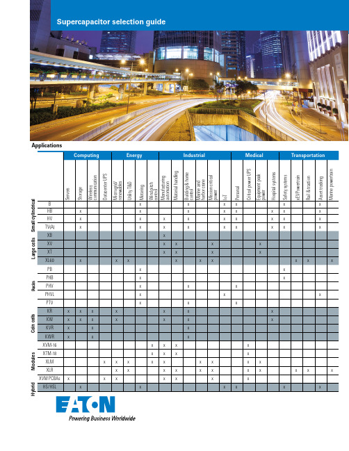
Lorem ipsum dolor sit amet Lorem ipsum dolor sit amet Lorem ipsum dolor sit ametApplicationsM o d u l e s C o i n c e l l sP a c k s L a r g e c e l l s S m a l l c y l i n d r i c a l H y b r i dSupercapacitor selection guideSmall cylindrical Features• Low resistance (ESR)• Wide operating temperatures • Extended operating temperature up to +85 °C with linear derating*• Fast charge/discharge• Highest power density Benefits• Long lifetimes, up to 20 years*• Maintenance free operation • Low total cost of ownership Applications• Smart utility meters• GPS and asset tracking devices • RF radios• Storage servers• Industrial backup/ride through • Automotive safety devices (emergency door locks, e-call)FamilyCapacitance(F)Part numberESR(mohm)Nominalvoltage (V)Leakagecurrent (μA)OperatingtemperatureSize(mm)0.22B0510-2R5224-R2000 2.52-25 °C to +70 °C 5 x 111.00B0810-2R5105-R5002.54-25 °C to +70 °C8 x 131.50B1010-2R5155-R3002.57-25 °C to +70 °C10 x 142.20B0820-2R5225-R200 2.59-25 °C to +70 °C8 x 203HB0820-2R5305-R155 2.57-25 °C to +70 °C8 x 205HB1020-2R5505-R95 2.511-25 °C to +70 °C10 x 206HB0830-2R5605-R95 2.511-25 °C to +70 °C8 x 3010HB1030-2R5106-R60 2.520-25 °C to +70 °C10 x 3015HB1325-2R5156-R45 2.522-25 °C to +70 °C13 x 2625HB1625-2R5256-R36 2.528-25 °C to +70 °C16 x 2535HB1635-2R5356-R28 2.532-25 °C to +70 °C16 x 3560HB1840-2R5606-R23 2.547-25 °C to +70 °C18 x 40110HB1860-2R5117-R18 2.5180-25 °C to +70 °C18 x 601HV0810-2R7105-R200 2.710-40 °C to +65 °C8 x 103HV0820-2R7305-R80 2.715-40 °C to +65 °C8 x 205HV1020-2R7505-R40 2.720-40 °C to +65 °C10 x 206HV0830-2R7605-R40 2.720-40 °C to +65 °C8 x 3010HV1030-2R7106-R34 2.723-40 °C to +65 °C10 x 3015HV1325-2R7156-R30 2.723-40 °C to +65 °C13 x 2625HV1625-2R7256-R27 2.745-40 °C to +65 °C16 x 2535HV1635-2R7356-R24 2.751-40 °C to +65 °C16 x 3535HV1245-2R7356-R20 2.751-40 °C to +65 °C12 x 4560HV1840-2R7606-R18 2.7110-40 °C to +65 °C18 x 40100HV1860-2R7107-R12 2.7260-40 °C to +65 °C18 x 603.3TV0820-3R0335-R75 3.015-40 °C to +65 °C8 x 206TV1020-3R0605-R35 3.013-40 °C to +65 °C10 x 2010TV1030-3R0106-R26 3.025-40 °C to +65 °C10 x 3015TV1325-3R0156-R24 3.035-40 °C to +65 °C13 x 2525TV1625-3R0256-R18 3.060-40 °C to +65 °C16 x 2534TV1245-3R0346-R16 3.075-40 °C to +65 °C12 x 4535TV1635-3R0356-R15 3.090-40 °C to +65 °C16 x 3560TV1840-3R0606-R13 3.0135-40 °C to +65 °C18 x 40100TV1860-3R0107-R11 3.0225-40 °C to +65 °C18 x 60 TVA25TVA1625-3R0256-R18 3.060-40 °C to +65 °C16 x 25 35TVA1635-3R0356-R15 3.090-40 °C to +65 °C16 x 3560TVA1840-3R0606-R13 3.0135-40 °C to +65 °C18 x 40100TVA1860-3R0107-R11 3.0225-40 °C to +65 °C18 x 60 BHBHVTVFamily Capacitance(F)Part numberESR(mohm)Nominalvoltage (V)Leakagecurrent (μA)Operatingtemperature Size (mm) 0.1PB-5R0(1)104-R4000 5.03-25 °C to +70 °C 5.5 x 10.8 x 12.50.47PB-5R0(1)474-R1000 5.07-25 °C to +70 °C8.5 x 16.8 x 141.0PB-5R0(1)105-R500 5.012-25 °C to +70 °C 8.5 x 16.8 x 21.51.5PHB-5R0(1)155-R310 5.010-25 °C to +70 °C8.5 x 16.8 x 21.52.5PHB-5R0(1)255-R190 5.014-25 °C to +70 °C10.5 x 20.8 x 22.53.0PHB-5R0(1)305-R190 5.016-25 °C to +70 °C8.5 x 16.8 x 31.5 5.0PHB-5R0(1)505-R120 5.025-25 °C to +70 °C 10.5 x 20.8 x 320.47PHV-5R4(1)474-R300 5.413-40 °C to +65 °C8.5 x 16.8 x 141.5PHV-5R4(1)155-R100 5.418-40 °C to +65 °C8.5 x 16.8 x 21.52.5PHV-5R4(1)255-R70 5.424-40 °C to +65 °C10.5 x 20.8 x 22.53.0PHV-5R4(1)305-R70 5.425-40 °C to +65 °C8.5 x 16.8 x 31.5 5.0PHV-5R4(1)505-R65 5.428-40 °C to +65 °C10.5 x 20.8 x 320.47PHVL-3R9(1)474-R400 3.91-40 °C to +65 °C 8.5 x 16.8 x 141.5PHVL-3R9(1)155-R160 3.92-40 °C to +65 °C 8.5 x 16.8 x 21.52.5PHVL-3R9(1)255-R803.94-40 °C to +65 °C 10.5 x 20.8 x 22.53.0PHVL-3R9(1)305-R80 3.94-40 °C to +65 °C 8.5 x 16.8 x 31.5 5.0PHVL-3R9(1)505-R70 3.95-40 °C to +65 °C 10.5 x 20.8 x 320.47PM-5R0(1)474-R420 5.08-40 °C to +60 °C8.5 x 16.8 x 141.0PM-5R0(1)105-R150 5.010-40 °C to +60 °C8.5 x 16.8 x 21.5 1.5PM-5R0(1)155-R70 5.015-40 °C to +60 °C10.5 x 20.8 x 22.53.0PM-5R0(1)305-R50 5.020-40 °C to +60 °C10.5 x 20.8 x 32 1.65PTV-6R0165(1)-R150 6.018-40 °C to +65 °C8.5 x 16.8 x 21.5 3.0PTV-6R0305(1)-R100 6.025-40 °C to +65 °C10.5 x 20.8 x 22.5 5.0PTV-6R0505(1)-R72 6.080-40 °C to +65 °C10.5 x 20.8 x 32Cylindrical packs Features• Integrated cell management/balancing bult-in• Low resistance (ESR)• Wide operating temperatures • Extended operating temperature up to +85 °C with linear derating*• Fast charge/discharge• High power densityBenefits• Long lifetimes, up to 20 years*• Maintenance free operation • Low total cost of ownership Applications• Smart utility meters• GPS and asset tracking devices • RF radios• Storage servers• Industrial backup/ride through • Automotive safety devices (emergency door locks, e-call)PBPHBPHVPMPTV1: “V” for straight leads, “H” for 90 degree bent leads PHVLHybrid supercapacitors Features• High power and ultra-high capacitance• Small footprints for space-saving (10.5 mm x 18 mm to 16.5 mm x 27 mm package sizes)• Wide range of operating temperatures (-25 °C to +70 °C)Benefits• Low ESR and leakage current to minimize power wastage• Lead and halogen-free, RoHS and REACH compliant,UL recognizedApplications• Industrial backup/ride through • Backup for storage servers• Water and gas smart meters • IoT energy storage• Medical backup power/alarm • Commercial trucks/containers asset tracking FamilyCapacitance(F)Part numberMaximuminitial ESRContinuouscurrentPeak current(A)Nominal leak-age currentPeak power(W) 10HS/HSL0814-3R8106-R15000.075 1.0 2.0/3.0 2.425HS/HSL0820-3R8256-R6500.125 2.3 2.5/3.3 5.530HS/HSL1016-3R8306-R5500.15 2.7 3.0/4.0 6.650HS/HSL1020-3R8506-R4500.25 3.4 4.0/5.08.070HS/HSL1025-3R8706-R2500.35 6.1 5.0/8.014120HS/HSL1225-3R8127-R2000.67.77.0/1218150HS/HSL1040-3R8157-R1400.7510.90.9/1626220HS/HSL1625-3R8227-R100 1.115.312/2536HS/HSLCoin cells Features• Multiple footprint configurations • Fully rated industrial operating temperature (KW/KVW family)• Eco-friendlyBenefits• Ultra low leakage current• Lower total install cost vs batteries with holders• Low total cost of ownership Applications• Real-time clock (RTC) backup • Memory backup• Utility meters• Medical devices• Industrial controls• Computers and peripherals • Network switches and routers • Appliances and white goodsFamilyCapacitance(F)Part numberESR(ohms)Nominalvoltage (V)Leakagecurrent (μA)OperatingtemperatureSize(mm)0.1KR-5R5C104-R75 5.50.6-25 °C to +70 °C13.5 x 7.50.22KR-5R5C224-R75 5.5 1.3-25 °C to +70 °C13.5 x 7.50.33KR-5R5C334-R50 5.52-25 °C to +70 °C13.5 x 7.50.47KR-5R5C474-R50 5.5 2.8-25 °C to +70 °C13.5 x 7.51.0KR-5R5C105-R30 5.56-25 °C to +70 °C21.5 x 7.51.0KVR-5R0C105-R30 5.010-25 °C to +70 °C21.3 x 8.11.5KR-5R5C155-R30 5.59-25 °C to +70 °C21.5 x 7.51.5KVR-5R0C155-R30 5.010-25 °C to +70 °C 21.3 x 8.10.1KR-5R5V104-R75 5.50.6-25 °C to +70 °C11.5 x 12.50.22KR-5R5V224-R75 5.5 1.3-25 °C to +70 °C11.5 x 12.50.33KR-5R5V334-R50 5.52-25 °C to +70 °C11.5 x 12.50.47KR-5R5V474-R50 5.5 2.8-25 °C to +70 °C11.5 x 12.51.0KR-5R5V105-R30 5.56-25 °C to +70 °C19 x 19.51.0KVR-5R0V105-R30 5.010-25 °C to +70 °C19.4 x 20.51.5KR-5R5V155-R30 5.59-25 °C to +70 °C19 x 19.51.5KVR-5R0V155-R30 5.010-25 °C to +70 °C 19.4 x 20.50.1KR-5R5H104-R75 5.50.6-25 °C to +70 °C11.5 x 50.22KR-5R5H224-R75 5.5 1.3-25 °C to +70 °C11.5 x 50.33KR-5R5H334-R50 5.52-25 °C to +70 °C11.5 x 50.47KR-5R5H474-R50 5.5 2.8-25 °C to +70 °C11.5 x 51.0KR-5R5H105-R30 5.56-25 °C to +70 °C19 x 6.51.5KR-5R5H155-R30 5.59-25 °C to +70 °C19 x 6.51.5KVR-5R0H155-R30 5.010-25 °C to +70 °C 19 x 19.50.1KW-5R5C104-R50 5.50.6-40 °C to +85 °C13.5 x 8.30.22KW-5R5C224-R50 5.5 1.3-40 °C to +85 °C13.5 x 8.30.33KW-5R5C334-R50 5.52-40 °C to +85 °C13.5 x 8.30.68KW-5R5C684-R30 5.5 2.8-40 °C to +85 °C21.5 x 9.00.68KVW-5R0C684-R30 5.010-40 °C to +85 °C21.3 x 111.0KW-5R5C105-R30 5.56-40 °C to +85 °C21.5 x 9.01.0KVW-5R0C105-R30 5.010-40 °C to +85 °C21.3 x 11 KR/KVR(cylindrical mounting)KR/KVR(vertical mounting)KR/KVR(horizontal mounting)KW/KVW(cylindrical mounting)Large cells Features• Low resistance (ESR), high power• Wide operating temperatures • Extend operating temperature up to +85 °C with linear derating*• Highest energy storage power densityBenefits• Long lifetimes, up to 20 years*• Maintenance free operation• Low total cost of ownership• No C-rate charge/discharge limitationsApplications• Engine and generator starting • Automotive active suspension • X-ray peak power• Material handling systems• Rail/Traction energy regeneration • Industrial backup power/UPS FamilyCapacitance(F)Part numberESR(mohm)Nominalvoltage (V)Leakagecurrent (μA)OperatingtemperatureSize(mm) 300XB3550-2R5307-R7.0 2.5300-25 °C to +70 °C35 x 50400XB3560-2R5407-R 4.5 2.5400-25 °C to +70 °C35 x 60600XB3585-2R5607-R 3.7 2.5700-25 °C to +70 °C 35 x 85300XV3550-2R7307-R 4.5 2.7480-40 °C to +65 °C35 x 50400XV3560-2R7407-R 3.2 2.7650-40 °C to +65 °C35 x 60600XV3585-2R7607-R 2.6 2.71300-40 °C to +65 °C 35 x 85275XT3550-3R0287-R 4.5 3.0600-40 °C to +65 °C36 x 54370XT3560-3R0377-R 3.2 3.0850-40 °C to +65 °C36 x 64555XT3585-3R0567-R 2.6 3.01300-40 °C to +65 °C 36 x 88.53000XL60-2R7308W-R0.23 2.75000-40 °C to +65 °C60 x 1383000XL60-2R7308T-R0.23 2.75000-40 °C to +65 °C60 x 1383400XL60-2R9348W-R0.23 2.858000-40 °C to +65 °C 60 x 1383400XL60-2R9348T-R0.23 2.858000-40 °C to +65 °C60 x 1383000XL60-3R0308W-R0.23 3.07000-40 °C to +65 °C60 x 1383000XL60-3R0308T-R0.23 3.07000-40 °C to +65 °C60 x 138 XBXVXTXL60Eaton is a registered trademark. All other trademarks are property of their respective owners.EatonElectronics Division 1000 Eaton Boulevard Cleveland, OH 44122United States/electronics © 2022 EatonAll Rights Reserved Publication No. 10594 July 2022Features• Integrated cell balancing and management• Wide operating temperatures • Simply wire in series and/or parallel to meet load needs •Highest energy storage power densityBenefits• Long lifetimes, up to 20 years*• Maintenance free operation • Low total cost of ownership•No C-rate type charge/discharge limitationsApplications• UPS backup power• Grid services & renewable firming• Commercial xEVs• Large material handling systems •Rail/Traction energy regenerationModulesFamilyCapacitance (F)Part number ESR(mΩ)Nominal voltage (V)Leakagecurrent (mA)Operating temperatureSize (mm)65XVM-16R2656-R 2216.223-40 °C to +65 °C 236 x 46 x 7862XTM-18R0626-R 2218.023-40 ° to +65 °C 236 x 46 x 78130XLM-62R1137A-R 6.762.1128-40 °C to +65 °C 686 x 176 x 173130XLM-62R1137A-T 6.762.1128-40 °C to +65 °C 686 x 176 x 173130XLM-62R1137B-R 6.762.1 5.2-40 °C to +65 °C 686 x 176 x 173130XLM-62R1137B-T 6.762.1 5.2-40 °C to +65 °C 686 x 176 x 173130XLM-69R0137A-R 6.769144-40 °C to +65 °C 686 x 176 x 173130XLM-69R0137A-T 6.769144-40 °C to +65 °C 686 x 176 x 173 130XLM-69R0137B-R 6.7697.0-40 °C to +65 °C 686 x 176 x 173130XLM-69R0137B-T 6.7697.0-40 °C to +65 °C 686 x 176 x 173166XLR-48R6167-R 5.048.6 5.2-40 °C to +65 °C 420 x 195 x 176188XLR-51R3187-R 5.051.38.0-40 °C to +65 °C 420 x 195 x 176500XLR-16R2507-R1.716.25.0-40 °C to +65 °C 416 x 67 x 1764.17XVM-259R2425-R 310259.227-40 °C to +65 °C 550 x 266 x 696.25XVM-259R2635-R 250259.228-40 °C to +65 °C 550 x 266 x 942.56XVM-315R9255-R 530315.923-40 °C to +65 °C 440 x 377 x 603.42XVM-315R9345-R 380315.924-40 °C to +65 °C 440 x 377 x 705.13XVM-315R9515-R 320315.925-40 °C to +65 °C 440 x 377 x 95XVM-16XTM-18XLMXLRXVM PCBAs* Supercapacitor lifetimes vary based on charge voltage and temperature. See Eaton’s application guidelines or contact your local Eaton sales representative for more information on lifetime estimates.XLR-LV。
立隆电子 SVLT系列超级电容器产品规格说明书

R & D May.06. 2019 Paul LinR & DMay.06. 2019Matt ChienR & DMay.06. 2019Vera Huang1. Part Number System 料号说明Product Code Guide –SVLT Series (-25~+85 ℃ 0.1F~1.50F) For example:① SCM means supercapacitor module ② Supercapacitor Type: D means EDLC type ③ Series : VLT means SVLT series -25~+85 ℃ ④ Rated Voltage : 5R5 means 5.5 V / 3R6 means 3.6V ⑤ Rated Capacitance:For example:⑥ Capacitance Tolerance:⑦ Lead Form & & ⑧ Dimension Code:⑨ ⑩ Special Notes: Defaulted without any note2. Product Dimensions: 产品尺寸SCM □□□ ① D □ ② VLT □□□ ③ 5R5 □□□ ④ 334 □□□ ⑤ Z □ ⑥ VH □□ ⑦ 115004□□□□□□ ⑧ E □ ⑨ XX □□ ⑩ HTYPE3.General Characteristics/一般特性4.Environmental Characteristics/环境特性5.Test Methods 测试方法5.1Capacitance 容量Charge capacitor with constant current to rated voltage, then charge it with constant voltage for 30 minutes, and then discharge it with constant current to 0.1V (safe voltage). 将电容器恒流充至额定电压,并恒压30min,然后恒流放至0.1V(安全电压)Recording time t1 and t2 corresponding to V2 and V1 during discharge(where V2=80%VR, V1=40%VR)。
超级电容规格书--BRP002R8L106FA (2.8V 10F)

自放电特性(电压保持特性) Self discharge characteristics (voltage holding characteristics)
正负极间电压大于等于 2.1V
测试条件
温度循环:-40±2℃→常温→+ 65±2℃→常温 循环次数:5 次
施加电压:0V 温度:+65±2℃ 时间:1000h
6
25℃ ∆V=2.16-1.08 I=50mA
步骤 1:+25±2℃ 步骤 2:-40±2℃ 步骤 3:+65±2℃ 步骤 4:+25±2℃
施加电压:2.8V 温度:+65±2℃ 时间:1000h 施加电压:2.8V 温度:+25±2℃ 循环次数:500000 次
项目
引出端强度 Lead strength 可焊性 Solder ability 高低温循环特性 Temperature cycle
BIGCAP®产品规格书
PRODUCT SPECIFICATION
产品类型(Product Type) : 产品型号(Product Model): 发布日期(Release Date) :
卷绕系列 BRP002R8L106FA
2016-04-01
Prepared 编制
Checked 审核
Approved 批准
存放寿命特性 Shelf life
湿热特性 Humidity Characteristics
容量 C ESR 漏电流 LC 外观 容量∆C ESR 漏电流 LC 外观 容量∆C ESR 漏电流 LC 外观
BRP002R8L106FA
引出端无损坏 超过 3/4 端子表面被锡层覆盖
满足初始规定值
无机械损伤或漏液 满足初始规定值 20%范围内 小于等于初始规定值 3 倍 小于等于初始规定值 无漏液或机械损伤 满足初始规定值 30%范围内 小于等于初始规定值 2 倍 小于等于初始规定值 4 倍 无漏液或机械损伤
超级电容器产品说明书

....................................................................... SPECIFICATIONSMODEL NO.: PCX-10F10 Farad Hybrid Super Capacitor with 3-Digit Blue Voltage Meter Capacitance.............................. 10,000.000 micro farad (10 Farad)Working Voltage........................................... 16 DCVSurge Voltage................................................. 20 DCVE. S. R. (Equivalent Series Resistance)......... 0.0015 ohm @ 120Hz / 25°CCapacitance Tolerance....................................± 10 %MODEL NO.: PCX-20F20 Farad Hybrid Super Capacitor with 3-Digit Blue Voltage Meter Capacitance.............................. 20,000.000 micro farad (20 Farad)Working Voltage........................................... 16 DCVSurge Voltage................................................. 20 DCVE. S. R. (Equivalent Series Resistance)…..... 0.0015 ohm @ 120Hz / 25°CCapacitance Tolerance...................................± 10 %MODEL NO.: PCX-30F30 Farad Hybrid Super Capacitor with 3-Digit Blue Voltage Meter Capacitance.............................. 30,000.000 micro farad (30 Farad)Working Voltage........................................... 16 DCVSurge Voltage................................................. 20 DCVE. S. R. (Equivalent Series Resistance)……. 0.0015 ohm @ 120Hz / 25°CCapacitance Tolerance...................................± 10 %DETAILED FEATURES:a) 3 digit super bright blue voltage meter measures 0.1V DVC range.b) Blue LED lighting window illuminates, and goes to sleep status when the amplifier isswitched off and there’s no voltage variation within 3 minutes.c) Reverse polarity connection warning buzzer. If the capacitor is connected incorrectlyby reversing the positive and negative wires during the installation process, the buzzer on the PCB will ring till you correct polarity connection.d) Over voltage limit and low battery voltage limit warning. When the system voltagegoes ABOVE 17 DCV or BELOW 10 DCV, the buzzer will issue warning sound.INSTALLATION AND MOUNTING:Securely mount the capacitor using supplied hardware. Be careful when choosing mounting location to avoid moving parts and possible exposure to moisture.CHARGING THE CAPACITOR AND WIRING:The capacitor must be charged before connecting the Power and Ground cables to the capacitor. Failure to charge the capacitor will result in a large spark generated from the rapid inflow of current.1. To charge the capacitor:Make capacitor positive terminal connections with amplifier and tighten the bolt. Do not over-tighten the bolt!Caution: Stripped terminals are not covered under the capacitor’s warranty.2. Connect the ground cables of the battery, amplifier, and capacitor separately tochassis.3. Place the supplied charging resistor between the positive terminal of the capacitor andthe battery’s positive terminal. After 5~60 seconds, the capacitor will be fully charged.Caution: The resistor will become hot!4. Immediately after the charging process, take away the charging bulb from theconnecting wire, and connect the positive cable to the positive terminal on the capacitor.CAPACITOR WIRING DIAGRAM:DISCHARGING THE CAPACITOR:Never remove the capacitor without discharging the stored power – it can give adangerous electrical shock!To disconnect the capacitor, follow these instructions:1. Disconnect the cables from the capacitor in the following order:a) positive (+) cableb) ground (-) cable2. Holding the resistor provided, touch the leads to the positive (+) and ground (-)terminals of the capacitor. After 1~5 minutes, the capacitor will be discharged (Thecharging resistor will become hot!) Then you can safely remove and handle it.WARNING!!THIS POWER CAPACITOR MAY EXPLODE AND CAUSE SERIOUS INJURY IF ABUSEDOR CONNECTED IMPROPERLY. PLEASE REFER TO THE INSTRUCTIONS CONTAINEDIN THIS MANUAL FOR CORRECT OUNTING, CHARGING/DISCHARGING AND WIRINGCONNECTION FOR THIS CAPAPCITOR PRIOR TO INSTALLATION.POWER ACOUSTIK AUDIO ACCESSORIES CAR AUDIO ACCESSORIES。
XLR超级电容器模块说明书
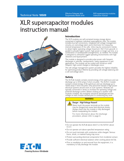
10509XLR supercapacitor modules instruction manualSafetyThe XLR-48 module contains stored energy of 54 watt-hours and can discharge up to 9700 amps if short circuited. The XLR-51 module contains stored energy of 69 watt-hours and can discharge up to 10200 amps if short circuited. Only personnel trained in high power electrical systems should work on such systems. Modules are typically connected in series to increase the operating voltage and potential discharge current. Before working on a system with modules installed, the module(s) should be discharged and the voltage on each module verified prior to conducting any work.IntroductionThe XLR modules are self-contained energy storage devicecomprised of eighteen individual supercapacitor cells. The module includes bus bar connections, integrated cell voltage management circuitry, an overvoltage alarm and a thermistor for measuringinternal temperature of the cells. Units may be connected in series to obtain higher operating voltage (maximum 750 V from ground), in parallel to provide higher current, high power or longer run time, or a combination of series/parallel arrangements, as needed. The module is designed to withstand rugged operating environments with high vibrations and liquid present.The module is designed to provide pulse power with frequent discharges in vehicles, transportation, heavy equipment or grid applications. The module can be cooled with forced air when frequent, high current charges or discharges occur.The cell voltage management system provides the highest reliability for optimizing product lifetime by providing cell voltage balancing and a cell overvoltage alarm.• D o not operate the XLR-48 above 48.6 V or the XLR-51 above 51.3 V .• D o not operate unit above specified temperature rating.• D o not touch terminals with conductors while charged. Serious burns, shock, or material fusing may occur.•P rotect surrounding electrical components from incidental contact.• P rovide sufficient electrical isolation when working above 50 Vdc.• P rior to installation on and removal from the equipment, it is mandatory to fully discharge the module.2Technical Note 10509Effective February 2019XLR supercapacitor modules instruction manualEATON /electronicsTheory of operationSupercapacitors function on electrostatic principles with no chemical reactions and no moving parts. They avoid the lifetime issuesassociated with chemical storage of batteries or mechanical issues associated with fly wheels. The XLR modules are non-toxic and designed for years of maintenance-free operation.Supercapacitors are intended as energy storage with a DC discharge. The module should not be used for AC charging ordischarging. Discharges may be constant current or constant power. Example discharges are shown in Figure 1a and 1b. The voltage of the module drops linearly under a constant current discharge.Figure 1a. E xample voltage and current discharge curves for 5 kW discharge fromone module with 48 V float voltage.S y s t e m V o l t a g e (V o l t s )S y s t e m C u r r e n t (A m p s )504030201002502001501005000 5 10 15 20Time (seconds)Discharge Current (A)Voltage (V)Figure 1b. E xample voltage and current discharge curves for 250 A discharge fromone module with 48 V float voltage.S y s t e m V o l t a g e (V o l t s )S y s t e m C u r r e n t (A m p s )50403020103503002502001501005000 5 10 15 20Time (seconds)Discharge Current (A)Voltage (V)Due to the very low equivalent series resistance (ESR) of the supercapacitors, minimal heat is generated during operation. However, as supercapacitors can handle very high currents, a significant heat rise can occur if the discharges and re-charging is frequent and above 50 Arms continuous current.Most systems require multiple modules connected in series to reach higher operating voltages. The XLR module can be series connected for operation up to 750 V (with respect to ground) to meet system level requirements and connected in parallel without limit to meet longer discharge times.Due to manufacturing variations in capacitance and leakage current, cells in a module can differ in voltage. This voltage difference affects the capacitance and equivalent series resistance over time and results in a shortening of the life of the system.The shunt balance circuit monitors the voltage of each cell. When the voltage on a cell exceeds 2.65 V preset in the XLR-48 and 2.95 V preset in the XLR-51, the balancing circuit will activate to discharge the cell back to appropriate levels.Figure 2. F our mounting points for the module.The module has 4 M8 mounting holes, as shown in Figure 2 and 3. A spacer may be needed between the top and bottom plate in high vibration environments. In moderate or low vibration environments, only the holes on the top or bottom plate are required for securing the module.369.2Negative T erminal M10196170.077Figure 3. D imensional drawing of module, all dimensions in mm.InstallationUnpackingInspect the shipping carton for signs of damage prior to unpacking the module. Damage to the shipping carton or module should be reported to the carrier immediately.Remove the module from the shipping carton and retain the shipping materials until the unit has been inspected and is determined to be operational.NOTE: The original shipping materials are approved for both air and ground shipment. The module should be removed from the shipping carton by lifting it by the body of the module.Contents:1 M odule1 M10 bolt, washer, lock washer (inserted into negative terminal)1 M8 bolt, washer, lock washer (Inserted into positive terminal)1 C ommunications mating connector wired (installed on communications connector)If the unit is found to be defective or any parts are missing, contact your local sales representative. A Return Material Authorization(RMA) number must be issued prior to returning the unit for repair or replacement.MechanicalModules are intended for installation horizontally as shown in Figure 5. The module should be mounted on a shelf as shown in figure 4. The modules should further be secured to the rack using the four mounting holes. See the data sheets for available mounting locations (click here).3Technical Note 10509Effective February 2019XLR supercapacitor modules instruction manual EATON /electronicsFigure 4. N i ne series connected modules mounted in a 24” rack. Modules can berotated 90 degrees for a narrower, deeper rack.Output terminal postsThe output terminals of the module consist of threaded aluminum, female posts . They are designed to connect directly to a ring lug or a bus bar. Apply a layer of high conductivity aluminum-aluminum anti-oxidant joint compound between the mating surfaces. The positive terminal is a threaded M8 female thread and the negative terminal is M10 female threaded. The maximum stack height of the lugs, bus bars and lock washers should be 0.6” (15 mm).The maximum depth of the threaded terminal is 20 mm. When applying torque to the terminals, it is recommended to use a maximum torque of 20 N-m / 14.8 ft-lbs.Attachment to the output terminals should be made with ring lugs or bus bars of an appropriate size for the application current and the M8/M10 terminal size. The energy storage modules have low ESR. As a result, the resistance of the cable connecting the energy storage module to the load can easily exceed the ESR of the module.Connection of modules in series or parallel or combination thereof should utilize the same gauge wire (or equivalent bus bar) asdetermined for final output connections. When connecting in series, connect the positive output terminal of one module to the negative output terminal of the next module (as shown in Figure 6 and Figure 8). For parallel connections, connect positive terminals together and negative terminals together (as shown in Figure 7 and Figure 8). When making parallel connections, it is recommended to make the connections at the load to ensure that the resistance across all strings is the same. It is not recommended to use the module terminals as a parallel connection point. The maximum operating voltage of a series connected system should not exceed 750 V . All cables connected to the module should have a strain relief to avoid damage to the module terminals in high vibrationenvironments. The cables should be secured to avoid free movement and vibrations on the terminals. This includes the monitoring cable.Figure 5.S eries connected modules (top view). In this example, the system couldprovide 20 KW for 15 seconds at 145.8 V maximum voltage when usingthe XLR-48 modules.Figure 6.P arallel connected modules (top view). In this example, the system couldprovide 20 KW for 15 seconds at 48.6 V maximum voltage when usingthe XLR-48 modules.Figure 7. 3 Series x 2 parallel connect modules. In this example, the system wouldprovide 20 kW for 33 seconds or 40 kW for 15 seconds at 145.6 V maximum voltage when using the XLR-48 modules. Recommended connection point for the parallel strings is at the load or a commonterminal block, not on a module terminal.Module-to-module balancingThe modules are equipped with voltage management circuitry that reduces the voltage on cells which exceed the rated voltage. The voltage management functions over hours to minimize the standby current requirements. Module-to-module balancing is not required as the balancing system works on each individual cell.4Technical Note 10509Effective February 2019XLR supercapacitor modules instruction manualEATON /electronicsOvervoltage SignalAn electrically isolated open collector logic output is made available for alarm interface. When the voltage exceeds 2.75 V or 3.0 V on any cell in the XLR-48 or XLR-51 modules, respectively, a signal will be triggered at alarm connector J1 present on module. When several modules are connected in series, parallel or series-parallel combination, the alarm logic output signal can be monitored individually or can be setup in a wire OR configuration to form a single fault signal from the string. It is recommended that each module be monitored individually to provide the greatest diagnostic capability in the field.Below table shows pin out indication of the connector, andmaximum current allowed. 5.0 Vdc can be the maximum open circuit voltage across connector provided.Overvoltage Signal Operation1. Overvoltage Pin 2 goes active (closes the circuit to ground) if any cell inside module exceeds overvoltage limit.2. Since Pin 2 (overvoltage signal) is an open collector transistor output, pull-up resistor (~1K) connected to a 5 V supply should be connected to Pin 2, as shown in Figure 9.3. When a simple pull up circuit is built around Pin 2, Pin 2 will remain ~5 V when there is no overvoltage which indicates normal operating condition. When the cell goes into over-voltage condition, Pin 2 goes low. This alarming signal can be used to signal system electronics to abort charging of module and to permit overcharged cells to appropriately discharge down to set limits, through a built-in active balancer4. The internal overvoltage circuit can sink up to 5 mA with an output signal low voltage of no more than 0.7 V . When there is no over voltage signal, maximum leakage current through pull up resistor is 100 nA. Based on the overall electronic system, proper value of the pull-up resistor should be selected.Temperature monitoringA thermistor is attached to a cell inside the module. This allowsmonitoring of the internal module temperature. The temperature can be monitored with a high impedance, constant current circuit and measuring the voltage.Figure 8. M onitor connector (Deutsch DTM06-4S). Outside the dotted line is arecommended implementation from the system.1423Diode or LEDPull-up resistor Voltage SourcePin #Signal nameOutputMaximumcurrentColor1GND 2Overvoltage High-not active Low-active5 mAWhite3Not used 4TemperatureSee tableBlackT able 1. M onitoring connector pinout where:I = current RMS AC or DC (amps)Resr = resistance Rac for AC current or Rdc for DC current (ohms) Rth = thermal resistance (o C/W) df = duty cycle fractionThis ∆T plus ambient should remain below the specified maximum operating temperature for the module (please refer to the module datasheet).OperationGeneralThe module should only be operated within specified voltage and temperature ratings. Determine whether current limiting is necessary on input/output based on current ratings of ancillary devices. Observe polarity indicated on module. Reverse polarity operation of the module(s) is not allowed for modules. Reverse polarity operation of the module will result in damage to the balancing circuitry.Electric isolation of the module is tested to 2500 V for maximum operating voltage of 750 Vdc.When several modules are connected in series for operating at higher voltage, care must be taken to ensure proper creepage and clearance distances in compliance with national safety standards for electrical equipment. Monitoring connectorA 4-pin connector (Deutsch DTM06-4S, mating connector DTM04-4P) is provided to monitor overvoltage conditions of cells and cell temperature. These provide warning indicators that a problem may exist in the module or can be monitored for extreme conditions. The connector should not be left to freely move. This will cause vibrations to damage the connector or wires to the connector. Secure the connector to the module, rack or cabinet. The pin definition is as follows:Thermal performanceLow internal resistance of the energy storage modules enables low heat generation within the modules during use. As with anyelectronic component, the cooler the part operates the longer the service life. In most applications natural air convection shouldprovide adequate cooling. In severe applications requiring maximum service life, forced airflow may be required.The thermal resistance, Rth, of the units has been experimentally determined assuming free convection at ambient (~ +25 ˚C). The Rth value provided on the data sheet is useful for determining the operating limits for the units. Using the Rth value a moduletemperature rise can be determined based upon any current and duty cycle. The temperature rise can be expressed by the following equation.5Technical Note 10509Effective February 2019XLR supercapacitor modules instruction manual EATON /electronics T (°C)T (°F)Resistance (k W )-40-40.0348.4-39-38.2325.5-38-36.4304.3-37-34.6284.7-36-32.8266.4-35-31.0249.4-34-29.2233.7-33-27.4219.0-32-25.6205.4-31-23.8192.7-30-22.0180.8-29-20.2169.8-28-18.4159.5-27-16.6149.9-26-14.8141.0-25-13.0132.6-24-11.2124.8-23-9.4117.5-22-7.6110.7-21-5.8104.3-20-4.098.33-19-2.292.74-18-0.487.50-17 1.482.59-16 3.277.98-15 5.073.66-14 6.869.61-138.665.81-1210.462.24-1112.258.88-1014.055.73-915.852.76-817.649.97-719.447.35-621.244.88-523.042.55-424.840.36-326.638.29-228.436.35-130.234.51T (°C)T (°F)Resistance (k W )032.032.78133.831.14235.629.6337.428.14439.226.76541.025.46642.824.23744.623.07846.421.96948.220.921050.019.941151.819.001253.618.121355.417.281457.216.481559.015.731660.815.011762.614.331864.413.691966.213.082068.012.502169.811.952271.611.422373.410.922475.210.452577.010.002678.89.5722780.69.1642882.48.7762984.28.4063086.08.0543187.87.7193289.67.4003391.47.0953493.2 6.8053595.0 6.5283696.8 6.2653798.6 6.01338100.4 5.77239102.2 5.543T (°C)T (°F)Resistance (k W )40104.0 5.32441105.8 5.11442107.6 4.91543109.4 4.72444111.2 4.54145113.0 4.36746114.8 4.20047116.6 4.04048118.4 3.88749120.2 3.74150122.0 3.60151123.8 3.46852125.6 3.33953127.4 3.21754129.2 3.09955131.0 2.98656132.8 2.87857134.6 2.77558136.4 2.67559138.2 2.58060140.0 2.48961141.8 2.40162143.6 2.31763145.4 2.23764147.2 2.15965149.0 2.08566150.8 2.01367152.6 1.94568154.4 1.87969156.2 1.81570158.0 1.75571159.8 1.69672161.6 1.64073163.4 1.58674165.2 1.53475167.0 1.48376168.8 1.43577170.6 1.38978172.4 1.34479174.2 1.301T (°C)T (°F)Resistance (k W )80176.0 1.26081177.8 1.22082179.6 1.18183181.4 1.14484183.2 1.10985185.0 1.07486186.8 1.04187188.6 1.00988190.40.978589192.20.948890194.00.920191195.80.892492197.60.865793199.40.840094201.20.815195203.00.791196204.80.767997206.60.745598208.40.723999210.20.7030100212.00.6828101213.80.6633102215.60.6444103217.40.6262104219.20.6086105221.00.5916106222.80.5751107224.60.5591108226.40.5437109228.20.5288110230.00.5144111231.80.5004112233.60.4868113235.40.4738114237.20.4611115239.00.4488116240.80.4369117242.60.4254118244.40.4142119246.20.4034120248.00.3929T able 2. Temperature monitoring Temperature monitoringA thermistor is attached to a cell inside the module. This allows monitoring of the internal module temperature. The resistance vs.temperature is shown in Table 2. The temperature can be monitored with a high impedance, constant current circuit and measuring the voltage.EatonElectronics Division 1000 Eaton Boulevard Cleveland, OH 44122United States/electronics© 2019 EatonAll Rights Reserved Printed in USAPublication No. 10509 BU-MC19023February 2019XLR supercapacitor modules instruction manualTechnical Note 10509Effective February 2019Eaton is a registered trademark.All other trademarks are property of their respective owners.Follow us on social media to get thelatest product and support information.Routine MaintenanceClean exterior surface of dirt/grime• Reason - Improve power dissipation performance.• U se a cleaning cloth dampened with a water/soap solution. Do not use high-pressure sprays or immersion • Frequency - AnnuallyCheck mounting fasteners for proper torque • Reason - Avoid mechanical damage • Frequency - AnnuallyInspect housing for signs of damage• Reason - Allows potential internal damage to be identified • Frequency - AnnuallyCheck signal/ground connections• Reason - Avoid false signals or shock hazards • Frequency - AnnuallyStorageThe discharged module can be stored in the original package in a dry place. Discharge a used module prior to stock or shipment. A wire across the terminals should be used to maintain short circuit after having discharged the module.DisposalDo not dispose of module in the trash. Dispose of according to local regulations for general electronics waste.SpecificationsPlease refer to datasheets (click here).MaintenancePrior to removal from the system, cable removal, or any other handling ensure that the energy storage module is completely discharged in a safe manner. The stored energy and the voltage levels may be lethal if mishandling occurs. Maintenance should only be conducted by trained personnel on discharged modules. Discharge ProcedureProceed as follow to discharge the module:1. Using a voltmeter, measure the voltage between the 2 terminals.2. I f the voltage is above 1 V , a resistor pack (not supplied with the module) will need to be connected between the terminals. Proper care needs to be taken in the design and construction of such a dissipative pack. e.g. At 48 V , for a 2 Ohm pack, the module will be discharged with a peak current of 24 A and will take about 18 minutes to discharge. The heat/power dissipated in the resistor pack will be ~ 1.2 kW. The resistor pack will need to be sized and provided with suitable cooling to handle this power dissipation. Additionally, proper enclosure or other packaging is necessary to ensure safety. In all cases, proper design of the dissipative resis-tor pack is necessary.3. I f the voltage is under 1 V , connect a shorting wire to the + and – connectors.4. T he module is now safe for handling. The shorting wire should be connected at all times until the module is installed in the system and the power cables are connected。
扣式超级电容器 5R5105Z-V 5.5V 1F V型规格书推荐

Rev. date: 08-SEP-17
6 of 8
w w w .liy o u k j.c o m
深圳理悠科技有限公司
SHENZHEN LIYOU TECHNOLOGY CO.,LTD
使用在有纹波电流流经的电路上时注意以下事项: (1)超级电容器内部电阻要比其他电解电容器高,纹波电流会使其发热,在预测其使用寿命时要加入考虑 范围; (2)请在加上纹波电流造成的电压变动部分的最大使用电压以下使用; (3)超级电容器内部电阻较高,一般不适用于纹波吸收,请用符合用途的低内阻产品。 9.3 周围温度对超级电容器的影响
72 h 串联保护电阻两端电压 UV;
R
V
Cx待测电容
根据下式计算漏电流:
LC UV 103 mA R
其中: LC:漏电流(mA) UV: 串联电阻两端电压(V) R: 串联保护电阻,一般 1000 Ω 以下(Ω)。
图 4.漏电流测试电路图
9. 注意事项和使用指导
为了确保安全,需使用超级电容器时,请与本公司联系咨询超级电容器的技术规格以及使用要求。 9.1 超级电容器的极性和使用电压
当主电源关闭时,超级电容器将从电源失效检验模式转为后备电源工作模式,此时由于瞬间启动电流及 电容内阻将导致开路电压下降。请根据相关产品介绍中所列出的阻抗和使用电流确定正确的产品型号。 9.5 串联
串联超级电容器时要保证电压平衡,可考虑将电阻器与超级电容器并联,而起到漏电分压的作用。 9.6 超级电容器的焊接
5. 环境性能指标 ................................................................ ................................ 4
南京超级电容规格

南京超级电容规格一、产品概述南京超级电容是一种高能量密度、高功率密度的新型电容器,具有快速充放电、长寿命、低内阻等优点。
本文将详细介绍南京超级电容的规格。
二、外观与尺寸1. 外观:圆柱形或方形2. 尺寸:- 圆柱形:直径5mm-60mm,长度5mm-100mm- 方形:边长5mm-60mm,高度5mm-100mm三、电气参数1. 额定电压:2.7V-3.0V(可根据客户需求定制)2. 容量范围:0.1F-500F(可根据客户需求定制)3. 最大允许工作电压:超过额定电压10%4. 最大允许泄漏电流:0.01CV(C为容量,V为工作电压)5. 最大允许瞬态电流:10倍额定电流6. 内阻范围:0.02Ω-0.1Ω四、环境参数1. 工作温度范围:-40℃~+85℃(可根据客户需求定制)2. 储存温度范围:-40℃~+70℃3. 湿度范围:≤75%RH五、应用领域南京超级电容广泛应用于以下领域:1. 电动车辆:用于动力回收、启动辅助、高功率加速等。
2. 新能源领域:用于储能系统、风力发电、太阳能发电等。
3. 工业自动化:用于UPS、稳压器、瞬态保护等。
4. 通信设备:用于基站备份、光纤通信等。
六、质量保证1. 产品符合ROHS环保要求。
2. 产品通过CE认证,符合欧洲标准。
3. 产品通过UL认证,符合北美标准。
七、包装方式1. 单个包装:盒装,塑料袋装,真空包装等。
2. 批量包装:纸箱包装,木箱包装等。
八、售后服务1. 提供全面的售前咨询和售后技术支持服务。
2. 对于质量问题的产品提供免费维修或更换服务。
九、结语南京超级电容是一种功能强大的新型电容器,具有诸多优点。
本文介绍了其外观尺寸、电气参数、环境参数、应用领域、质量保证、包装方式和售后服务等方面的规格。
我们相信,南京超级电容将在各个领域发挥重要作用,为人们的生产和生活带来更多便利。
WTC5V51F5Z-0720C 超级电容器 产品规格书说明书
产品规格书产品名称: 超级电容器产品型号: WTC5V51F5Z-0720C变更履历表版本修订人变更内容变更日期R21.1 任倩倩1、增加了最大峰值电流(1s) 2021.09.24目录质量声明 (4)1. 适用范围 (5)2. 标准测试条件 (5)3. 一般特性 (5)4. 包装方式 (5)5. 环境性能指标 (6)6. 产品尺寸及外形 (6)7. 命名规则 (7)8. 测试方法 (7)9. 注意事项和使用指导 (9)10. 免责声明 (11)质量声明正确的使用和维护保养才能确保您的电容(或电容系统)长期可靠稳定地运行。
⚫收到产品后,请检查包装是否完好,若包装破损,可能导致产品损坏。
若有损坏,请于五个工作日内联系我司售后或销售人员。
⚫凡不按本说明书规定进行使用或维护保养者,视同放弃保修权利,上海闻亭实业有限公司及其服务站有权不再予以保修,对由此而产生的一切损失也不予以赔偿,但可以根据情况提供相应的有偿服务。
⚫贵司在收到产品及产品说明书后,请于7日内回复。
7日内未回复,我司将视客户承认此产品及产品说明书符合贵司要求。
公司信息地址:上海市黄浦区广西北路528号电话:+86-021-********邮编:200001邮箱:******************网址:1. 适用范围本产品规格书描述了上海闻亭实业有限公司(以下简称闻亭信息)生产的圆柱式超级电容器的产品性能指标。
2. 标准测试条件一般情况下,在标准大气压下,温度15~35 o C,相对湿度在25%~75%条件下进行测试;测试前样品应该在测试温度下放置12 h以上,本规格书的测试条件为标准大气压,温度为25±2 o C,相对湿度为60±15%。
3. 一般特性测试项目规格/条件1 型号WTC5V51F5Z-0720C2 额定容量 1.5 F3 容量偏差-20 % ~ + 80 %4 工作电压 5.5V5 浪涌电压 6.0 V6 标称内阻交流阻抗20 Ω直流阻抗30 Ω7 产品重量8.5±0.05g8 最大峰值电流(1 s) 90mA9 漏电流(24 h) ≤0.02mA10 工作温度-40 ~ 70 o C11 储存温度-40 ~ 85 o C12 循环寿命25ºC,额定电压到半额定电压间循环充放电50万次,|∆C/C|≤30%,ESR≤4倍初始值(25ºC)4. 包装方式产品型号包装数量(只)包装箱尺寸(L×W×H, mm)整箱重量(Kg)每外箱每吸塑盘每内箱每外箱每吸塑盘每内箱WTC5V51F5Z-0720C80 400 1600 331×228×117 485×355×265 16±15. 环境性能指标项目规格/条件1 温度特性+70 o C时|∆C/C|≤30 %,ESR≤规定值(25 o C)-25 o C时|∆C/C|≤50 %,ESR≤4倍初始值(25 o C)2 高温负荷特性+70 o C ± 2加额定电压,1000h后,|∆C/C|≤30%,ESR≤4倍规定值。
- 1、下载文档前请自行甄别文档内容的完整性,平台不提供额外的编辑、内容补充、找答案等附加服务。
- 2、"仅部分预览"的文档,不可在线预览部分如存在完整性等问题,可反馈申请退款(可完整预览的文档不适用该条件!)。
- 3、如文档侵犯您的权益,请联系客服反馈,我们会尽快为您处理(人工客服工作时间:9:00-18:30)。
®KAMCAP
Create PDF files without this message by purchasing novaPDF printer ()
Kamcap supercapacitor product specification τ 充电至0.632×UR的时间(s); R 串联电阻(Ω)。 选择R值使τ为60s~120s。 (7)设备:开关 直流电压表 电阻 函数记录仪
其中
C 容量(F);
I 放电电流(A);
U1 测量初始电压(V); U2 测量终止电压(V); t1 放电初始到电压达到U1(s)的时间; t2放电初始到电压达到U2(s)的时间。 放电电流I及放电电压下降的电压U1和U2参见表2。
表2 – 放电条件
分类
HT、HV、X
SE、HE
SP、MK
LR、HP、HEV、LEV
■
®KAMCAP
Create PDF files without this message by purchasing novaPDF printer ()
Kamcap supercapacitor product specification 1 适用范围SCOPE:
Kamcap supercapacitor product specification
11 KAMCAP性能测试方法 (1)依据标准
IEC 62391-1《Fixed electric double-layer capacitors for use in electronic equipment – Part 1:Generic specification》
SE-5R5-D224VY 50
800
4800 270×195×95 415×295×310
10.75
®KAMCAP
Create PDF files without this message by purchasing novaPDF printer ()
测量方法 采用恒流放电方法所示的测量电路,采用额定电压。用电压记录仪测量电容器端电压。 将开关S切换至直流源,当恒流恒压源达到额定电压后施加电压充电30min。 在充电30min结束后,切换开关S至恒流放电装置,以表3中规定的恒定电流进行放电。用电 压记录仪记录电容器端电压随时间变化。由电压记录仪得到的电压与时间成直线部分绘制辅 助线,从辅助线与放电开始交点读取电压降ΔU3,如图5所示,根据下式计算内阻Rd。
本产品基于双电层电容器原理,内部采用活性炭作为正负电极,两极间用电解液与隔膜隔 开,不锈钢外壳。引出极在产品同侧。
®KAMCAP
Create PDF files without this message by purchasing novaPDF printer ()
02
0.22
(F 25℃ ΔV=1.5V-1.25V I=0.01A)
03 容量允许偏差Capacitance tolerance
+10%~+30%
04 额定电压Rated Voltage U0 (V) 05 工作温度范围Operating temperature range
5.5 -25℃~70℃
±20%
T
474 -10%~20% U
1.0
105 10%~30% V
2.0
205 -30%~50% W
3.3
335
4.7
475
8.0
805
10
106
20
206
30
306
50
506
90
906
100
107
120
127
150
157
300
307
600
607
1500
158
3500
358
5000
508
引出方式 螺柱型 引线型 接触型
®KAMCAP
Create PDF files without this message by purchasing novaPDF printer ()
Kamcap supercapacitor product specification
6 KAM标识 KAM MARK
电压(V)
图2 电容器的端电压特性
时间(s)
®KAMCAP
Create PDF files without this message by purchasing novaPDF printer ()
Kamcap supercapacitor product specification
高温无负荷特性 11
High temperature without load
+70℃±2,1000±4h后,︱△C/C︱≤30%,ESR ≤2倍规定值。
湿热负荷特性 12
Humidity Resistance
+40℃±2, 90--95%RH,240h,︱△C/C︱≤30%,IL ≤2倍规定值,ESR≤4倍规定值。
Kamcap supercapacitor product specification
PRODUCT SPECIFICATION 产品规格书
PART NO.
产品型号:
Customer
客户名称:
Customer P/N 客户料号:
Issue Date
发布日期:
SE-5R5-D224VY 2007-8-15
应用
后备记忆
能量存储
功率
瞬时功率
充电时间
30min
30min
30min
30min
I(mA)
1×C
0.4×CUR
4×CUR
40×CUR
U1
充电电压的80%值(0.8×UR)
U2பைடு நூலகம்
充电电压的40%值(0.4×UR)
备注 C为额定容量单位为F(法拉),UR为额定电压单位为V(伏)。
注 放电电流I应按以下规定选取:
Q/KMNY001-2006《电化学电容器》 (2) 测试方法
容量capacitance 1、恒流放电方法constant current discharge method 2、测量电路
恒流/恒压源
恒流放电装置
直流电流表 直流电压表 转换开关 待测电容
图1 – 恒流放电方法电路
(3) 测量方法measuring method ◎ 恒流/恒压源的直流电压设定为额定电压(UR)。 ◎ 设定表2中规定的恒电流放电装置的恒定电流值。 ◎ 将开关S切换到直流电源,在恒流/恒压源达到额定电压后恒压充电30min。 ◎ 在充电30min结束后,将开关S变换到恒流放电装置,以恒定电流进行放电。 ◎ 测量电容器两端电压从U1到U2的时间t1和t2,如图2所示,根据下列等式计算电容量值:
温度特性 09
Temperature characteristics
+70℃时︱△C/C︱≤30%,ESR≤规定值(25℃) -25℃时︱△C/C︱≤50%,ESR≤4倍初始值(25℃)
高温负荷特性 10
High temperature load
+70℃±2加额定电压,1000h后,︱△C/C︱≤30% ,ESR≤4倍规定值。
06 最大等效串联电阻ESR(Ω 1KHz)
40
07 最大直流内阻(Ω 0.01A)
60
加额定电压,常温循环充放电实验10
08 循环寿命Cycle life Expectancy
万次。︱△C/C︱≤30%,ESR≤4倍初
始值(25℃)
5 环境指标(Environmental)
项目
规格/条件
Item
Specification/Condition
仪
(5)恒电阻充电方法
测量电路
应根据图3中所示测量电路进行测量。
恒压源
R 串联电阻 S 开关
直流电压表 Cx 待测电容
图3 – 恒电阻充电方法电路 (6)测量方法
进行测量前,将电容器两端短路30min以上进行充分放电; 当施加直流电压UR时,测量时间常数(τ),通过下列等式计算电容量值:
其中 C 容量(F)
○1
○2 ○3
7 KAM型号KAM type
○1 、凯美商标 KAM Brand ○2 、负极标志 Cathode sign ○3 、额定容量及额定电压
Rated capacitance and rated voltage
系列代号
电压符号
结构类型
标称容量
容量偏差 引出方式 附加符号
系列 功率型 能量型
Kamcap supercapacitor product specification
10 实验数据Test result (1) 温度特性Tempercture characteristics
(2) 寿命特性Life characteristics
(3)漏电流曲线:
®KAMCAP
Create PDF files without this message by purchasing novaPDF printer ()
本产品规格书对产品的性能,测试方法进行了规范,作为技术确认的依据。 2 一般特性General Specification: 2.1 产品应用范围:
该产品可在电子装置中如:RAM、智能仪表、马达驱动、时钟电路、玩具等领域使用, 作为后备电源。 2.2 标准测试条件:
一般情况下,在标准大气压,温度5~35℃,相对湿度小于85%条件下进行测试;本规格 书标准测试条件为标准大气压,温度25℃,相对湿度小于60%。 2.3 依据标准:
代号 SP SE
额定电压(V) 电压符号 结构类型