继电器翻译
专业英语考试词汇翻译
可以确保90%以上正确,个别差错敬请谅解1. Feedback ; 反馈2. Error ;误差3. Open-Loop;开环4. Automatic Control System;自动控制系统5. Sensor;传感器6. Actuator;执行器7. Valve;阀8. Control Strategy;控制策略9. Positive feedback;正反馈10. Set point;设定值11. Inertia;惯性12. Centrifugal;离心的13. steam engine;蒸汽机14. mathematical model ;数学模型15. Routh Stability Criteria ;劳斯稳定性判据16. linear system ;线性系统17. amplifier ;放大器18. response ;响应19. artificial;模拟的,人造的20. industrial robot;工业机器人21. Maximum principle;最大值原理22. Dynamic;动态的23. Neural network control;神经网络控制24. Fuzzy control;模糊控制25. Predictive control;预测控制26. Programmable Logic Controller;可编程序逻辑控制器(PLC)27. Distributed Control System;分布式控制系统28. Fieldbus ControlSystem;现场总线控制系统29. Supervisory ControlSoftware;监控软件30. Configuration Software;组态软件31. object;目标32. V ariable Structurecontrol ;可变结构控制33. Sliding-mode control;滑模控制34. Proportional ;比例35 Integral;积分36. Derivative;微分37. offset;补偿38. Avoid overshoot;避免超调39. performance;性能40. logic;逻辑41. function;功能42. Triangle function;三角函数43. Trapezoid function;梯形函数44. robots;机器人45. Instruction ;指令46. Relay;继电器47. Processor;处理器48. Wiring;布线49. mechanisms;机械装置50. nut;螺母51. bolt;螺栓52. concept ;概念,观念53. weld ;焊接54. spray ;喷雾器55. communicate;通讯,传递56. orbit;轨道57. install ;安装58. metal ;金属59. plastics;塑料60. rubber;橡胶61. electronics;电子62. packaging;封装63. complexity;复杂64. millimeter;毫米65. asynchronous;异步的66. accurate;精确67. debug;调试68. slot;槽口69. armature;电枢70. iron core;铁芯71. eddy;涡流72. flux;磁通量73. conductor;导体74. commutator;换向器75. brush;电刷76. stator;定子77. rotor;转子78. bearing;轴承79. aluminium铝80. slip ring;滑环81. copper;铜82. torque;转矩83. opposite;相反84. wound;绕组,缠绕85. squirrel cage rotor;鼠笼转子86. insulate;隔离87. embedded;嵌入式88. cylindrical;圆柱体89. salient;凸出的90. magnetic field;磁场91.efficiency;效率92. permanent magnet;永磁铁93. gear;齿轮94. twisted ;缠绕95. characteristic ;特性96. proportional to ;与。
电梯专业英语中文翻译
main drive sprocket 主驱动链轮
main drive wheel 主驱动装置
main drive wheel 主驱动轮
main floor 基站
main landing 基站
main landing door switch 基站门开关
long wait landing call 候梯时间较长的层站呼梯
longitudinal 纵向的
Long's lay rope 同向捻(顺捻)钢丝绳
loop 环圈
loop circuit 环形电路
loop current 环流
loose bearing 松配轴承
loose fit 动配合
main circuit breaker 主断路器
main circuit control 主电路控制
main contact 主触点
main contactor 主接触器
main drive 主驱动装置
main drive chain 主驱动链
main drive chain guard 主驱动链保护装置
mallet 木槌
managanese bronze 锰青铜
mandatory 强制的
manganese 锰
manhole 人孔
man-hour coutput 人小时产量
manipulation 利用,操纵
manipulator 操纵器,机械手
man-made fiber 人造纤维
magnetic clutch 磁性离合器
magnetic detector 磁力检查器
纸业专业英语词汇翻译(E)

纸业专业英语词汇翻译(E)纸业专业英语词汇翻译(E)纸业专业英语词汇翻译(E)eggshell book paper 蛋壳表面状整饰书籍用纸elastic paper 伸性(牛皮)纸elastic cable paper 电缆纸elastic cable fitting paper 电缆芯衬纸electrical paper 电气用纸electrical discharge recording paper 放电记录纸electrical insulating paper 电(气)绝缘纸electrical electro-chemical sensitive recording paper 电化学感应记录纸electrical-chemical telephotographic paper 电化学传真纸electrical-conductive paper 导电纸electrical-fax paper 直接法静电复印纸,氧化锌静电复印纸electrical-graphic paper 电谱纸electrical-photographic paper 静电复印纸electrical-photographic copy paper 电子感光复印纸electrical-photographic printing paper 电子印刷纸electrical-photographic recording paper 电子记录纸electrical-recording paper 电子记录纸electrical-sensitive paper 电敏金属纸electrical-sensitizing recording paper 电感记录纸electrical-static copying paper 静电复写纸electrical-telephotographic paper 电传真原纸electrical-thermosensitive recording paper 电热感记录纸electrolytic paper 电解纸electrolytic paper(for electroph-oresis) 电泳纸electrolytic capacitor paper 电解电容器纸electrolytic recording paper 电解记录纸embossed paper 提花纸,压印浮雕纸,压花纸blotting 压花吸墨纸blotting cover paper 压花封皮纸blotting glassine paper 提花玻璃纸blotting printing paper 压花印刷纸emery paper 钢砂纸enamel(ed) paper 铜版纸enamel book paper 涂布书籍纸enameled blotting paper 粘附在蜡光纸上的吸墨纸enameled postcard 涂布明信片卡片纸enameled end bands paper 卷简纸端都保护用纸end paper 环衬纸end leaf paper 环衬纸end leaves 环衬纸end sheet 环衬纸engish opacity paper 英国式不透明纸engraver's proving paper 凹版印刷校样纸enrober paper 糖果杯纸envelope-lining tissue 信封衬里薄纸envelope manila 马尼拉信封纸envelope paper 信封纸erasable parchment bond 可擦性仿羊皮纸esparto paper 西班牙草浆制成的纸张etching paper 雕刻用纸excelsior tissue paper 刨花纸excelsior wrapper 木丝包袭纸exercise book paper 练习本用纸expandable paper 伸性纸express fiber paper 货物包装纸express paper 货物包装纸extensible paper 伸性(牛皮)纸extra high bulk book paper 超松厚度书籍纸extras 超令纸extra strong paper 超强统extrusion coated paper 挤压涂布纸eggshell board 蛋壳纸板eleatrical board 电气用纸板eleatrical insulating board 电绝缘纸板eleatrical press board 电气绝缘压榨纸板electro-insulating board for air medium 空气介质电绝缘纸板embossed hard board 提花纤维板embossing board 提花纸板excelsior board 木丝板esparto board 西班牙草浆纸板extrusion coater 挤压式涂布机e folute e极瓦楞纸波形数(每天30厘米,96+-3个)early stage of cooking 蒸煮初期early wood 早材earth flax 石棉ease of solubility 易溶性easily hydrolyzable lindage 易水解的结合键eastern arbor-vitae(thuja occidentalis l.) 香柏,西方金钟柏eastern black walnut(juglans nigra) 黑胡桃eastern hemlock (tsuga laricina k. koch) 美国落叶松eastern red cedar (juniperus virginiana l.) 铅笔柏ebonise 假鸟木eony(wood) (diospyros ebenum) 鸟檀,鸟木ecentric growth 偏心年轮ecentric spindle 偏心轴eclipsed from 重叠形eco filter eco 白液澄清器ecology 生态学economic analysis 经济分析economic feasibility 经济合理性,经济可行性economizer 省煤器;省油器eddy 涡流eddy current 涡流edge 棱,边,边缘edge crush test 边缘压溃试验edge curl 卷边edge cutter 切边器edge doctor 边刮刀edge effect 边缘效应edge grain (木材)纵断面edge guide 纸幅校正器edge protector 边缘护体edge runner 碾磨机,碾子edge tear 边缘撕裂度edge tearing resistance 边缘撕裂强度edgewise compression strength (纸板)边缘抗压强度edgings 边材;纸边eduction pipe 排气管eductor 喷射器,引射器effective alkali 有效碱effective drying surface 有效表面;有效面积effective surface 有效表面;有效面积effervescence 泡腾;起泡(沫)effeciency 效率effeciency of drying 干燥效率effluent 废水,排出污水effluent disposal 废水处理effluent treatment 废水处理effluent treatment plant 废水处理车间effulgence 光泽egg carton 蛋品包装纸盒egg trap 蛋品包装用塑料纸板eggshell rinish 粗装饰;蛋壳状装饰eight mo octave 八开eject valve 排渣阀ejetor 喷射器ekcothern 纸板制品商业名称(供厨房用)elaborated product 加工产品elapsed time counter 越时计数器elastic calender bowl 弹性压光辊elastic fiber 弹性纤维elastic modulus 弹性模量,弹性模数elastic strength 弹性强度elasticity 弹性;弹力;弹性力学elastomer 弹性体elder(samrucus) 接骨木(属)election bristol 选票用纸electric circuit 电路electric conductor 导电体electric connector 电气接插件electric controller 电控制器electric comverter 变压器;变频器;转化器electric data processing 电力处理数据electric discharge 放电electric drive 电力驱动(装置)electric eye 光电池;电眼electric fuse 电熔丝,保险丝electric impedance 阻(电)抗,电阻electric insulation 电绝缘electric moisture meter 电力湿度计electric motor 电动机electric plate precipitator 电板除尘器electric power 电力;电功率electric power distribution 电力分布electric relay 继电器electric resistance 电阻electric saw 电锯electric utility 电气设施electric valve 电动阀门electrical conductivity 电导率electrical double layer 双电层electrical dust precipitation chamber 电气除尘室electrical dust precipitator 电沉降净化器electrical engineering 电工学electrical fiber 电绝缘纤维electrical precipitator 静电除尘器electrical presspahn 电气用纸板electrical properties 电性质electrical repair shop 电气修理工段electrical resistivity 电阻率electrode 电极electrodialysis 电渗析electrofax 电子传真复印;电子传真复印纸eletrograph 电记录器;电版机;电传照像图electrokinetic potential 电动势,动电势electrolysis 电解electrolyte 电解质;电离质;电解液electrolytic cell 电解(电)池electrolytic dissociation 电离(作用)electrolytic printing 电解印刷electromagnetic field 电磁场electron diffraction 电子衍射electronic consistency regulator 电子浓度调节器electronic control 电子控制electronic dirt counter 尘埃度电子测定仪electronic equipment 电子装置electronic instrument 电子仪器electronic microgage 电子厚度计electronic microscope 电子显微镜electronic probe 电子探头electronic probe sensor 电子探头传感器electronic speed regulator 电子调速器electro-osmosis 电渗electrophoresis 电泳electrophoretic mass transfer technique 电泳质量传递技术electrophoretic mobility 电泳淌度electrophotography 静电摄影electro-precipitation 电沉降净化electro-reel 电动(轴式)卷纸机electro-static charge 静电装料electro-static coating 静电涂布electro-staticfacsimile system 静电传真系统electro static gravure printing 静电照相凹版印刷electro-static latent image 静电潜像electro-static precipitator 静电除尘器electrostatic printing 静电印刷electrostatic recording 静电记录electrostatic transfer 静电转写electrostatography 静电记录electrostatics 静电学elementary fibril 原细纤维,原纤维elevator 提升机elm(ulmus) 榆属;榆树elongation 伸长率elongation at rupture 裂断时伸长率elrepho reflectance meter elrepho 白度计eluant 洗提液eluate 洗出液elution 洗提elutriate 淘选,淘析,淘洗elutriation 淘析,淘洗elutriation method 淘选法elutriator 淘析器elutriator 嵌入;埋置;灌封embosser 压纹机,压花机embossing 压花,印花embossing calender 印花压光机embossing capacity 压花能力embossing machine 印花机embossing roll 印花辊embryo 胚emergency pump 备用泵emergency repair 紧急修理emergency valve 安全阀emery 金刚砂emission 放射;发射;辐射emission spectroscopy 放射光谱学empirical formula 经验式emptying 放料;放空emptying device 放料装置emptying door 放料门emptying valve 放料阀emulsification 乳化作用emulsifier 乳化器emulsify 乳化emulsifying agent 乳化剂emulsifying tank 乳化槽emulsion 乳胶,乳液emulsion breaker 乳胶分解剂emulsion xanthation 乳态黄酸酯化enamel 搪瓷encapsulated emulsion 微囊化encode 编码encrust 结壳end band 卷筒纸端部用保护纸end crush test 垂直抗压强度试验end product 成品end (surface)hardness 端面硬度end wall 侧壁;端墙endless chain log haul-up (无端)链条拉木机endless felt 无端毛毯endless wire 无端铜网endless woven felt 无端毛毯endosperm (种子)内胚乳endothermal 吸热的endothermic 吸热的endothermic reaction 吸热反应endurance test 耐久试验energy consumption 能量消耗;动力消耗energy transfer 能量传递engelmann's spruce 恩氏云杉engine dyeing 机内染色engine sizing 机内施胶english finish 低光泽低平滑度装饰english plane (platanus acerifolia) 英国悬铃木english reel 英国式卷纸机engraver's bristol 凹版厚纸engraving roll 刻花辊,雕刻辊engraving steel 雕刻板enolic hydroxyl 烯醇羟基enriched water 浓白水entanglement 交织entering reel 待裁切纸卷,待退纸卷enthalpy 焓,热函entomology 昆虫学entrainment 雾沫entrainmentn separator 雾沫分离器entrapped air 留截空气entropy 熵entry end 入口端envelope 信封;外壳;外套;包皮envelope cartridge 信封纸envelope machine 信封制造机envelope manila 马尼拉信封纸environment (周围)环境environmental pollution 环境污染environmental protection 环境保护environmental stress cracking 环境应力分裂enzymatically liberated lignin 酵素游离木素enzyme 酶,酵素enzyme converted corn starch 酶化玉米淀粉enzyme treated starch 酶处理淀粉enzymolysis 酶解ephemeral 一年生epibromohydrin 表溴醇,3-溴-1,2-环氧丙烷epichlorohydrin 表氯醇,3-氯-1,2-环氧丙烷epidermal tissue 表皮组织epidermis 表皮epidermis cell 表皮细胞epimanool 表甘露糖醇epins (木材)扭纹斑epithelial cell 分泌;细胞层;沟周细胞epithelial parenchyma 上皮薄壁细胞epithelium 上皮epoxy resin 环氧树脂epsom salt 七水合硫酸镁;泻盐(商业名称)equalization basin 稳定糖equalizing basin 稳定糖equilibrirm concentration 平衡浓度equilibrirm moisture 平衡湿度equilibrirm water 平衡水equipment 设备equivalent weight (化合)当量erasability 耐擦性能erasable parchment bond 耐擦高级羊皮纸erasing quality 耐擦性能erasure 耐擦性erect 安装eremacarsis 缓慢氧化;(木材露天堆放)慢腐侵蚀erkensator 立式离心除砂机erosion 腐蚀;侵蚀er-we-pa former er-we-pa 成形器escape pipe 排气管;放空管esparto 西班牙草essential oil 香精油ester 酯ester group 酯基ester number 酯化值ester value 酯化值esterification 酯化(作用)etched roll 蚀刻辊ethane 乙烷ethanol 乙醇ethanol lignin 乙醇木素ethanolamine 乙醇胺ether 乙醚ether extract 乙醚抽出物ether soluble substance 乙醚可溶物etherification 醚化(作用)ethyl acetate 醋酸乙酯ethyl acrylate 丙烯酸乙酯ethyl alcohol 乙醇ethyl amine 乙胺ethyl cellulose 乙基化纤维素ethyl group 乙基ethyl meraptan 乙硫醇ethylated starch 乙基化淀粉ethylation 乙基化(作用)ethylene 乙烯;乙撑;次乙基ethylene group 乙烯基;乙撑基;次乙基ethylene diamine 乙(撑)二胺,乙二胺1,2 ethyleneimine 乙(撑)亚胺,吖丙啶,氮丙环eucalyptus (eucalyptus) 桉树属eucalyptus (eucalyptus globulus) 蓝桉eugenol 丁子香粉eureca refiner eureca 磨浆机european ash (fraxinus excelsior) 欧洲白蜡树european beech(fagus sylvatica l.) 欧洲山毛榉european birch(betrla alba. l) 欧洲桦european chestnut (castanes sativa mill.) 欧洲粟european fir (abies pectinata) 欧洲白冷杉european hophorn beam (ostrya carpinifolia) 欧洲铁木european horse-chestnut(aesculus hippocustanum) 欧洲七叶树european larch(larix decidua) 欧洲落叶松european lime (tilia vulganis) 欧洲椴木european plane(platanus acerifolia) 英国悬铃木european yew (taxus baccata) 欧洲紫杉eutrophication 营养质量鉴定试验evacuate 抽空evaluation 评价,评定evaluation test 评价试验evaporate 蒸发evaporated liquor 蒸发液evaporating capacity 蒸发能力evaporation 蒸发作用evaporation area 蒸发面积evaporation feed liquor 蒸发器进料evaporator 蒸发器evaporator man 蒸发工evaporator room 蒸发工段evaporator tank 蒸发槽even-aged forest 同龄材even-edged stand 同龄幼树even-side 双面同性evener plate 匀浆板evener (roll) 匀浆辊evergreen oak(quercus ilex l.) 常绿楮,常青栎evolution 展开;演变;进化ewnn solution 酒石酸钠溶液excavator 挖掘机;挖土机excelsior 刨花excelsior cutting machine 木丝机excelsior plate 木丝板excelsior wrapper 木丝包装纸excess air 过剩空气excessive cutting 过量裁切exchange capacity 交换能力exchange reaction 交换反应exchanger 交换器excited state 激发态excrescence burl 异状瘤(树病)exhaust 抽空;排气;使疲劳exhaust end 排出端;卸料端exhaust fan 排风机exhaust gases 排出气体exhaust hood 排气罩exhaust steam 排出蒸汽exhaust valve 排气阀;放气阀exhauster 排气机exharstion 排气;抽空;疲劳exit end 出口端exothermic 放热的exothermic reaction 放热反应expand 扩张;膨胀;延伸expandable box 可伸纸盒expandable mandrel 可伸支架,可伸骨架expander roll 展毯辊;舒展辊expanding shaft 胀缩(卷纸)轴expajnsion 膨胀expansion shell type heater 膨胀壳式加热器expansion trap 膨胀式除水器expansiveness 膨胀性能expansivity 膨胀性expediting setting 快速凝固experimental beater 实验室打浆机experimental paper machine 试验纸机experimental station 试验站experimentation 实验工作,试验(方法)exploded fibers 爆炸法纤维explosion chamber 扩散室;爆炸室exposed bark pocket 外夹皮express mill wrapper 货物包装纸expulsion of water 脱水extender 伸长器,拉伸器extensibility 伸长性extensible 可伸长extension 伸展,扩建;伸出部分extensometer 伸长计exterior plywood 耐风化胶合板external bus 外汇流条,外部总线external fibrillation 表面细纤维化,表面纤细化,表面帚化external protective tissue 表面防护薄纸external screw 阳螺丝external treatment 厂外处理exlinction coefficient 消光系数extra hour work 加班extract 抽提,萃取extract of log wood 洋苏木浸青extraction 抽提,萃取extraction chamber 碎浆机(排浆区)extraction -free wood 无抽提物木材试料extractor 抽提器,提取器extraction plate (碎浆机)底部筛板extractive 抽提物;萃取物extractive-free wood 无抽提物木材试料extractor roll 分离辊,剥纸辊extraneous components 杂质extruder 挤压机extruding laminator 挤压裱糊机extruding machine 挤压机extrusion 挤压extrusion coating 挤压涂布extrusion die 挤压模extrusion head 挤压器端部,挤压头exudation 渗出exudation of resin 树脂渗出eye screw 环首螺丝elastic paper 伸性(牛皮)纸elastic cable paper 电缆线elastic cable fitting paper 电缆芯衬纸electrical paper 电气用纸electrical discharge recording paper 放电记录纸electrical insulating paper 电(气)绝缘纸electro-chemical sensitive recording paper 电化学感应记录纸electrolytic paper 电解纸electrolytic paper(for electrophoresis) 电泳纸electrolytic capacitor paper 电解电容器纸electrolytic recording paper 电解记录纸embossed paper 提花纸,压印浮雕纸,押花纸embossed glassine paper 提花玻璃纸embossed printing paper 压花印刷纸emery paper 钢砂纸enamel(ed) paper 铜版纸enameled blotting paper 粘附在蜡光纸上的吸墨纸end paper 环衬纸english opacity paper 英国式不透明纸engraver's proving paper 凹版印刷校样纸enrober paper 糖果杯纸envelope paper 信封纸electro-conductive paper 导电纸electro-fax paper 直接法静电复印纸,氧化锌静电复印纸electro-graphic paper 电谱纸electro-photographic paper 静电复印纸electro-photographic copy paper 电子感光复印纸electro-photographic printing paper 电子印刷纸electro-photographic recording paper 电子记录纸electro-recording paper 电子记录纸electro-sensitive metallic paper 电敏记录纸electro-static copying paper 静电复写纸electro-sensitizing recording paper 电感记录纸electro-telephotographic paper 电传真原纸electro-thermosensitive recording paper 电热感记录纸esparto paper 西班牙草浆制成的纸张etching paper 雕刻用纸exercise book paper 练习本用纸expandable paper 伸性纸extensible paper 伸性(牛皮)纸extrusion coated paper 挤压涂布纸electrographic process (复制)电显影法easy bleach pulp 易漂浆esparto pulp 西班牙草浆eucalyptus pulp 桉木浆exploded pulp 爆炸法纸浆export pulp 出口纸浆embossed cigarettetissue 罗纹卷烟纸electrolytic tissue 电解用薄纸envelope lining tissue 信封衬里薄纸excelsior tissue 高级薄纸external protective tissue 表面保护用纸ec embedded costs插入成本的缩写ecf elemental chlorine free无元素氯(漂白)的缩写edta ethylene eiamine tetraacetic acid乙二胺四乙酸的缩写epc experimental prismatic calcite实验棱镜方解石的缩写erv estimated replacement value预计取代值的缩写esp electrostatic precipitator静电滤尘器的缩写esp emergency shutdown procedure事故停机程序的缩写eva ethylene vinyl acetate乙烯乙酸乙烯酯的缩写espra empire state paper research associates国立造纸研究会的缩写evoh ethylene-vinyl alcohol乙烯-乙烯醇的缩写eurocell 欧洲林产品有限公司的司标纸业专业英语词汇翻译(E) 相关内容:。
电气工程及其自动化专业英语 Chapter 7 Power System Protections

Section 1 Introduction
(6)Phase sequence relays such as (i) negative sequence relays and, (ii) zero sequence relays, (7)Differential relays and percentage differential relays, (8)Distance relays such as (i) plane impedance relays, (ii) angle impedance relays, i.e. Ohm or reactance relays, (iii) angle admittance relays, i.e. Mho relays and, (iv) offset and restricted relays, (9)Pilot relays such as (i) wire pilot relays, (ii) carrier channel pilot relays, (iii) microwave pilot relays.
Chapter 7
Power System Protections
Section 1 Introduction
Text
New Words and Expressions Resume
Exercises
End
Section 1 Introduction
The steady-state operation of a power system is frequently disturbed by various faults on electrical equipment. To maintain the proper operation of the power system, an effective, efficient and reliable protection scheme is required. Power system components are designed to operate under normal operating conditions. However, if due to any reason, say a fault, there is an abnormality, it is necessary that there should be a device which senses these abnormal conditions and if so, the element or component where such an abnormality has taken
AD元器件英文对照
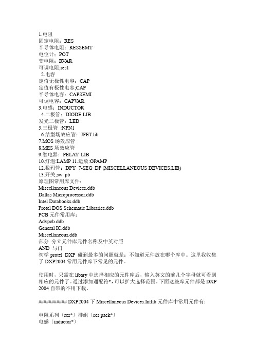
1.电阻固定电阻:RES半导体电阻:RESSEMT电位计;POT变电阻;RV AR可调电阻;res12.电容定值无极性电容;CAP定值有极性电容;CAP半导体电容:CAPSEMI可调电容:CAPV AR3.电感:INDUCTOR4.二极管:DIODE.LIB发光二极管:LED5.三极管:NPN16.结型场效应管:JFET.lib7.MOS场效应管8.MES场效应管9.继电器:PELAY. LIB10.灯泡:LAMP 11.运放:OPAMP12.数码管:DPY_7-SEG_DP (MISCELLANEOUS DEVICES.LIB)13.开关;sw_pb原理图常用库文件:Miscellaneous Devices.ddbDallas Microprocessor.ddbIntel Databooks.ddbProtel DOS Schematic Libraries.ddbPCB元件常用库:Advpcb.ddbGeneral IC.ddbMiscellaneous.ddb部分分立元件库元件名称及中英对照AND 与门初学protel DXP 碰到最多的问题就是:不知道元件放在哪个库中。
这里我收集了DXP2004常用元件库下常见的元件。
使用时,只需在libary中选择相应的元件库后,输入英文的前几个字母就可看到相应的元件了。
通过添加通配符*,可以扩大选择范围。
下面这些库元件都是DXP 2004自带的不用下载。
########### DXP2004下Miscellaneous Devices.Intlib元件库中常用元件有:电阻系列〔res*〕排组〔res pack*〕电感〔inductor*〕电容〔cap*,capacitor*〕二极管系列〔diode*,d*〕三极管系列〔npn*,pnp*,mos*,MOSFET*,MESFET*,jfet*,IGBT*〕运算放大器系列〔op*〕继电器〔relay*〕8位数码显示管〔dpy*〕电桥〔bri*bridge〕光电耦合器( opto* ,optoisolator )光电二极管、三极管〔photo*〕模数转换、数模转换器〔adc-8,dac-8〕晶振〔xtal〕电源〔battery〕喇叭〔speaker〕麦克风〔mic*〕小灯泡〔lamp*〕响铃〔bell〕天线〔antenna〕保险丝〔fuse*〕开关系列〔sw*〕跳线〔jumper*〕变压器系列〔trans*〕????〔tube*〕〔scr〕〔neon〕〔buzzer〕〔coax〕晶振〔crystal oscillator〕的元件库名称是Miscellaneous Devices.Intlib, 在search 栏中输入*soc 即可。
电子工程专业词汇英语翻译
a frame a 形杆a pole a 形杆a register 累加寄存器abend 任务异常结束abnormal current 异常电流abnormal end of task 任务异常结束abnormal glow discharge 反常辉光放电abnormal radiation 异常辐射abnormal reflection 异常反射abnormal voltage 异常电压abrasion 磨蚀abrasion resistance 抗磨性abrupt change 突然变化abruption 断裂abscissa 横坐标absolute 绝对的absolute accuracy 绝对准确度absolute block 绝对闭塞absolute calibration 绝对校准absolute capacity 绝对容量absolute coding 绝对编码absolute constant 绝对常数absolute delay 绝对延迟absolute electrical units 绝对电单位absolute electrode potential 绝对电极电势absolute electromagnetic unit 绝对电磁单位absolute electrometer 绝对静电计absolute electrostatic unit 绝对静电单位absolute error 绝对误差absolute galvanometer 绝对检疗absolute humidity 绝对湿度absolute level 绝对级absolute measurement 绝对测量absolute method of measurement 绝对测量法absolute peak 绝对峰值absolute permeability 绝对磁导率absolute permittivity 绝对电容率absolute potential 绝对电势absolute pressure 绝对压力absolute sensitivity 绝对灵敏度absolute slip 绝对转差率absolute speed drop 绝对转速降absolute speed rise 绝对转速升absolute speed variation 绝对转速变动absolute stability 绝对稳定性absolute system of electrical units 绝对电单位制absolute temperature 绝对温度absolute term 绝对项absolute unit 绝对单位absolute voltage drop 绝对电压降absolute voltage rise 绝对电压上升absolute zero 绝对零度absorption 吸收absorption band 吸收带absorption circuit 吸收电路absorption coefficient 吸收系数absorption control 吸收控制absorption current 吸收电流absorption curve 吸收曲线absorption plane 吸收面absorption wavemeter 吸收式波长计absorptive dielectric 吸收性电介体absorptive power 吸收能力abstract 文摘ac 交流ac analog computer 交粒拟计算机ac distribution 交龄电ac servomechanism 交僚服机构ac servomotor 交僚服电动机ac shunt motor 交林激电动机ac transmission 交龄电ac watt hour meter 交羚度表ac welder 交羚焊机accelerated ageing test 加速老化试验accelerated life test 加速寿命试验accelerating chamber 加速室accelerating force curve 加速力曲线accelerating relay 加速继电器accelerating torque 加速转矩acceleration 加速acceleration constant 加速常数acceleration lag 加速滞后acceleration relay 加速继电器acceleration time 加速时间accelerative force 加速力accelerator 加速器accelerometer 加速度计acceptance tests 验收试验acceptor 受主access arm 存取臂access mechanism 存取机构access time 存取时间accessibility 可达性accessor 存取机构accessory apparatus 辅助设备accidental coincidence 偶然符合accidental error 偶然误差accommodation 第accounting routine 费用计算程序accumulated dose 累积剂量accumulated error 累积误差accumulation 积蓄accumulator 二次电池accumulator battery 蓄电池accumulator cell 蓄电池单元accumulator charge 蓄电池充电accumulator discharge 蓄电池放电accumulator drive 蓄电池牵引accumulator insulator 蓄电池绝缘体accumulator plate 蓄电池极板accumulator railcar 电瓶机动车accumulator rectifier 蓄电池整流accumulator room 蓄电池室accumulator switch 蓄电池开关accumulator voltage 蓄电池电压accuracy 准确accuracy class 精度等级accuracy grade 准确度accuracy of measurement 测量准确度accuracy of reading 读数准确accuracy rating 准确度acid 酸acid proof 耐酸的acid resisting 耐酸的acknowledge character 肯定字符acknowledgement 肯定应答aclinic line 无倾线acoustic material 吸音材料acoustic memory 音存储器acoustic oscillation 声振荡acoustic signal 音响信号acoustic wave 声波acoustical frequency 声频across the line moter 直接起动电动机across the line starter 直接起动器across the line starting 直接起动acryl resin 丙烯尸acsr 钢芯铝线action correction 动作校正action current 动作电流action potential 动作电位action principle 作用(量)原理activated substance 激活物质activation 激活activator 活化剂active 活动的active circuit 有效电路active component 有效部分active current 有效电流active electric network 有源电网络active energy meter 有功电度表active load 有效负载active material 活性物质active polar surface 有效极面active power 有功功率active power relay 有功功率继电器active quadripole 有源四端网络active transducer 有源换能器active voltage 有功电压active wires 有效导线active zone 有效区activity coefficient 活度系数activity curve 放射性曲线actual current 有效电流actual efficiency 实际效率actual flux density 有效感应密度actual loading test 实际负载试验actual output 有效输出actual size 实际尺寸actual tooth density 有效齿端磁通密度actual value 实际值actual value sensor 有效值传感器actuating mechanism 操作机构actuating motor 伺服电机actuating quantity 作用量actuating signal 起动信号actuator 执行机构acute exposure 急性暴露acyclic dynamo 单极发电机acyclic generator 单极发电机acyclic machine 单极电机ad converter 模拟数字转换器adaptation 适应adaptation time 适应时间adapter 转接器adaptive control 自适控制adaptive control of machine tool 机床自适应控制adaptive equalizer 自适应均衡器adc 模拟数字转换器add even check 奇偶校验add pulse 加法脉冲added circuit 加法电路addend 加数adder 加法器adder subtracter 加减器adding element 加法元件adding network 加法网络addition agent 助剂addition cascade 相加级联ear 线夹earth 接地earth bar 接地棒earth capacity 对地电容earth circuit 大地电earth clamp 地线夹earth conductivity 大地电导率earth conductor 接地导线earth connection 接地earth current 大地电流earth current meter 大地电另earth dam 土坝earth detector 泄漏指示器earth electrode 接地电极earth fault 接地故障earth fault protection 接地保护装置earth fault relay 接地故障继电器earth jack 接地插孔earth lead 接地导线earth leakage circuit breaker 漏电保护断路器earth leakage current 漏地电流earth magnetic field 地磁场earth magnetism 地磁earth plate 接地板earth plate resistance 接地板电阻earth potential 地电位earth pressure 地压earth resistance 接地电阻earth resistance meter 接地电阻测量计earth resistor 接地电阻earth return 大地回路earth return circuit 地回路earth return system 地回路方式earth rod 接地棒earth terminal 接地端子earth wire 架空地线earthed 接地的earthed circuit 接地电路earthed neutral 接地中线earthed neutral system 接地中线系统earthenware conduit 陶瓷管道earthenware duct 陶瓷管道earthenware pipe 陶瓷管earthing bus 接地母线earthing conductor 接地导线earthing contact 接地接点earthing device 接地装置earthing inductor 接地感应线圈earthing resistance 接地电阻earthing switch 接地开关earthing system 接地网络earthing terminal 接地端子earthing transformer 接地变压器earthquake 地震earthwork 土方工程ebonite 硬橡胶ebonite plate 硬橡胶板ebullition 沸腾eccentric 偏心轮eccentric position 偏心位置eccentricity 偏心率echo check 返回检查economic dispatch 经济等economic life 经济寿命economic load dispatching 经济负荷等economical current density 经济电淋度economical loading 经济负载economical operation 经济运行economizer 省煤器economy 经济eddy 涡流eddy current 涡流傅科电流eddy current brake 涡疗动器eddy current braking 涡疗动eddy current circuit 涡羚路eddy current damping 涡凌尼eddy current dynamometer 涡力率计eddy current field 涡痢eddy current loss 涡琉失eddy current loss factor 涡琉耗系数eddy current motor 涡羚动机eddy currents 涡流edge effect 边缘效应edge notched card 边缘切口卡片edge position control 边缘位置控制edgewise winding 扁绕绕组edison accumulator 铁镍蓄电池edison effect 爱迪生效应edison screw cap 爱迪生灯泡头edison socket 螺口插座education of automatics 自动化教学effect 效应effect of capacity 电容效应effect of inductivity 感应率效应effective 有效的effective admittance 有效导纳effective area 有效面积effective current 有效电流effective energy 有效能量effective half life 有效半衰期effective head 净落差effective impedance 有效阻抗effective inductance 有效电感effective load 有效负载effective mass 有效质量effective output 有效功率effective payload 有效营业载荷effective permeability 有效磁导率effective power 有效功率effective radius 有效半径effective range 有效测量范围effective reactance 有效电抗effective resistance 有效电阻effective steepness 有效陡度effective value 均方根值effective voltage 有效电压effective work 有效功effectiveness 有效性efficiency 效率efficiency curve 效率曲线efficiency test 效率试验effluent 溢流egg insulator 蛋形绝缘子eigenfunction 本寨数eigenvalue 本盏eigenvector 固有向量ejector 喷射器elastance 倒电容elastic collision 弹性碰撞elastic control 弹性控制elastic deformation 弹性变形elastic feedback 弹性反馈elastic feedback controller 弹性反馈控制器elastic limit 弹性极限elastic modulus 弹性模数elastic scattering 弹性散射elasticity 弹性elbow 弯管electric 电的electric alarm 电警报electric apparatus 电气装置electric appliance 电气七electric arc 电弧electric arc furnace 电弧炉electric balance 电力秤;电平衡electric bell 电铃electric blanket 电毯electric bleaching 电漂白electric boiler 电热锅炉electric brake 电力制动器electric braking 电气制动electric brazing 电热铜焊electric bread toaster 电气烘面包炉electric breakdown 电哗electric brooder 电热式育雏器electric bus 电动公共汽车electric calorimeter 电气量热器electric capacity 电容electric car 电车electric charge 电荷electric charge surface density 电荷表面密度electric charge time constant 充电时间常数electric charge volume density 电荷体密度electric chronograph 电动记时器electric circuit 电路electric clock 电钟electric conduction 电气传导electric conductivity 电导率electric conductor 导体electric contact 电接点electric control 电力控制正方翻译网作者:正方翻译网l network l 形网络label 标记labile equilibrium 不稳定平衡laboratory 实验室laboratory equipment 实验设备labyrinth packing 迷宫式密封lac 漆lacquer 漆lacquer film 喷漆薄膜ladder 梯子ladder network 梯形网络lag 滞后lag theorem 延迟定理lagging current 滞后电流lagging device 滞后装置lagging load 滞后负载lagging phase 滞后相位lagging power factor 滞后功率因数lambert 朗伯lamella 薄板lamellar field 非旋场lamina 薄板laminar flow 层流laminated brush 叠片电刷laminated brush switch 叠片刷触点开关laminated core 叠片铁心laminated dielectric 叠片介质laminated insulation 叠片绝缘laminated magnet 叠片磁铁laminated plastic 层压塑料lamination factor 叠层系数lamination insulation 叠钢片绝缘lamp 灯lamp bracket 灯架lamp bulb 玻璃泡lamp circuit 电灯电路lamp cord 灯绳lamp efficiency 电灯效率lamp globe 灯泡lamp guard 灯泡保护网lamp holder 灯座lamp load 电灯负载lamp post 灯杆lamp shade 灯罩lamp signal 灯光信号lamp socket 灯座lamp test 灯泡试验lamp with internal diffusion coating 内扩散灯泡land 陆landing 登陆landing area floodlight 着陆探照灯landing light 着陆灯language processor 语言处理程序lap joint 叠式焊接lap parallel winding 迭绕组lap welding 搭接焊lap winding 迭绕组laplace operator 拉普拉斯算符laplace plane 拉普拉斯平面laplace transformation 拉普拉斯变换laplace's equation 拉普拉斯方程laplace's law 拉普拉斯定律laplacian 拉普拉斯算符lapping 重叠large scale integrated circuit 大规模集成电路large scale integration 大规模集成laser 睐泽;激光laser beam 激光束laser cutting 激光切割laser heating 激光加热laser machining 激光加工laser optics 激光学laser welding 激光焊接last in first out list 后进先出表latch 闭锁latch locking 插销锁定latching electromagnet 闭锁电磁铁latching relay 闭锁继电器latency 等待时间latency time 等待时间latent electricity 束缚电latent heat 潜热latent oscillations 潜伏振荡latitude effect 纬度效应latour motor 自励单相换向歧动机lattice 格子lattice coil 蜂房式线圈lattice network 桥型网络lattice tower x 形塔lattice type filter 桥式滤波器law 定律law of electromagnetic induction 电磁感应定律law of electrostatic attraction 库仑定律law of regulating action 第酌定律law of similarity 相似定律lawrence tube 彩色显象管lay 绞lay ratio 扭绞系数layer 层layer insulation 层间绝缘layer insulation test 层间绝缘试验layer of a distributed winding 分布绕组的层layer short 层间短路laying 敷设laying of cable 敷设电缆layout 布置lead 铅;超前;导线lead accumulator 铅蓄电池lead acid cell 铅酸电池lead covered cable 铅皮电缆lead covered wire 铅皮线lead covering 铅皮lead foil 铬箔lead in 引入lead in insulator 引入绝缘子lead in wire 引入线lead inductance 引线电感lead lag circuit 超前滞后电路lead loss 铅耗lead network 超前网络lead screen 铅屏蔽lead sheath 铅皮lead sheathed cable 铅皮电缆lead sheathing 铅皮lead shield 铅屏lead sleeve 铅套筒lead zirconate titanate 锆钛酸铅leader 先导;引线leader cable 引线电缆leading current 超前电流leading edge of brush 电刷前缘leading in cable 引入电缆leading in pole 引入杆leading in tube 引入线套管leading in wire 引入线leading load 电容性负载leading phase 超前相位leading pole tip 前极边leading power factor 超前功率因数leading through 引入套管leads 引线leaf electrometer 箔验电计leaf electroscope 箔验电器leak 漏leak detector 漏泄检验器leak resistance 泄漏电阻leak test 泄漏试验leakage 漏leakage coefficient 漏泄系数leakage conductance 漏电导leakage current 漏电流leakage factor 漏泄系数leakage field 漏泄场leakage flux 漏磁通leakage indicator 检漏计leakage inductance 漏磁电感leakage loss 漏泄损失leakage meter 漏泄计leakage path 泄漏通道leakage path length 漏电路径长度leakage rate 泄电率leakage reactance 漏电抗leakage reactance voltage 漏电抗电压leakage transformer 漏磁变压器leakance 漏泄电导leakance per unit length 每单位长度的漏泄电导learning control 学习控制least squares method 最小二乘法least squares technique 最小二乘法leaving signal 起动信号leblanc connection 勒布朗克接法leblanc exciter 勒布朗克励磁机lecher wires 勒谢尔线leclanche cell 勒克朗谢电池left hand rule 左手定则left handed twist 左扭转leg 变压弃芯柱legal ohm 法定欧姆legal unit 法定单位length 长度length of span 跨度距离lens 透镜lens turret 透镜旋转台lenz's law 楞次定律leonard control 伦纳德控制lepton 轻子lethal dose 致死射线量lethal exposure 致死性照射letharge 勒letter 字母level 水平level compensator 电平补偿器level compound excitation 平复励level crossing 平面交叉level diagram 电平图level fixing 电平固定level measurement 电平测量level meter 电平计level recorder 能级分布;能级记录仪level regulator 电平第器level transmitter 能级传送器lever 杠杆lever drive 杠杆式传动lever light 操纵杆指示灯lever lock 杆锁lever switch 杠杆开关leyden jar 莱登瓶lichtenberg's figure 李庭博图lid 盖life 寿命life curve 寿命曲线life test 寿命试验life time 寿命lift 升降机lifting magnet 起重磁铁lifting motor 起重电动机lifting speed 提升速度light 光light beam 光束light beam oscillograph 光束示波器light center 光中心light conductor 光导管light distribusion curve 配光曲线light distribution 光分配light filter 滤光器light flash 闪光light house lamp 灯塔灯light industry 轻工业light load 轻负载light output ratio 照莽率light output ratio of a fitting 光源效率light pen 光笔light relay 光继电器光控继电器light resistance 耐光性light running 无载运转light sensitiveness 光敏度light sensitivity 光敏度light signal 灯光信号light source 光源light spectrum 光谱light spot galvanometer 光电检疗light spot instrument 光点指示式仪表light spot scanner 光点扫描设备light valve 光阀light water power reactor 轻水动力堆light water reactor 轻水堆light wave 光波lighting 照明lighting cable 照苗缆lighting circuit 照苗路lighting engineering 照盲程lighting equipment 照描备lighting fitting 照娩件lighting load 照煤载lighting network 照螟路lightning 闪电lightning arrester 避雷器lightning conductor 避雷针lightning current 雷电流lightning discharge 雷闪放电lightning disturbance 雷害lightning generator 人造闪电发生器lightning path 雷痪径lightning proof transformer 避雷变压器lightning protection 避雷设备lightning resistant power line 耐雷输电线lightning rod 避雷针lightning stroke 雷击lightning stroke current 雷荤流lightning stroke recorder 雷磺录器lightning surge 雷电过电压lightning switch 避雷篇关like charges 同极性电荷like poles 同名极limit 界限limit cycle 界限周期limit indicator 极限指示器limit load 极限负载limit load operation 极限负载运行limit of measurement 测量范围limit switch 限制开关limit tolerances 界限公差limit value 极限值limit value threshold 极限值阈limiter 限制器limiter circuit 限制电路limiting characteristic function 有限特性函数limiting no damage current 不溶极限电流limiting resistance 限羚阻limiting value 极限值line 线路line absorption 线吸收line battery 线路电池line break 断线line breaker 断路器line capacity 线路容量line charging capacity 线路充电容量line conductor 线路导线line constant 线路常数line construction 线路架设line current 线路电流line drop 线路电压降line drop compensation 线路压降补偿line equipment 线路设备line fault 线路故障line feeder 补强馈电导线line hardware 线路金具line impedance 线路阻抗line insulation 线路绝缘line insulator 线路绝缘子line insulator string 线路绝缘子串line isolating switch 线路断路器line length 线路长度line location 线路勘查line losses 线路损耗line of electric force 电力线line of flow 吝line of force 力线line of magnetic force 磁力线line of magnetic induction 磁感应线line of magnetization 磁化线line of zero variation 无偏线line pattern 电力网图line protection 线路保护line reactor 线路感应器line relay 线路继电器line resistance 线路电阻line section 线段line short circuit 线路短接line simulator 仿真线line switch 线路开关line terminals 线路线端line to earth voltage 线路对地电压line to line short circuit 线间短路line to line voltage 线间电压line voltage 线路电压line voltage drop 线路电压下降linear actuator 线性传动装置linear attenuation 线性衰减linear characteristic 线性特性linear circuit 线性电路linear conditions 线性状态linear control 线性控制linear control system 线性控制系统linear detection 线性检波linear device 线性装置linear distortion 线性失真linear element 线性元件linear expansion 线性膨胀linear expansion coefficient 线性膨胀系数linear filter 线性滤波器linear four terminal network 线性四端网络linear function 线性函数linear induction motor 线性感应电动机linear integrated circuit 线性集成电路linear interpolation 线性内插法linear motor 线性电动机linear network 线性网络linear operator 线性算符linear oscillations 线性振荡linear polarization 线性极化linear potentiometer 线性电位计linear power amplifier 线性功率放大器linear programming 线性规划linear resistance 线性电阻linear scale 线性标度linear synchronous motor 线性同步电动机linear system 线性系统linearity 直线性linearity control 线性蝶linearity error 线性误差linearity in phase 相位的线性linearity theorem 线性理论linearization 线性化linearization range 线性区linearizing circuit 线性化电路lineman 线路工人lineman climbers 线路工脚扣lines of force density 力线密度lining 衬里link 环节link fuse 熔线片;链熔线link insulator 串式绝缘子link line 连络线linkage 连锁linkage coefficient 磁链系数liquefied natural gas 液化天然气liquid 液体liquid cooling 液体冷却liquid crystal 液晶liquid damper 液体阻尼器liquid damping 液体阻尼liquid dash pot 液体阻尼器liquid dielectric 液体电介质liquid expantion type thermostat 液体膨胀式恒温器liquid fuel 液体燃料liquid fuse 液体熄弧保安器liquid helium 液氦liquid insulation 液体绝缘liquid junction potential 液体接触电位liquid level control 液面第器liquid level controller 液面第器liquid level governor 液面第器liquid level indicator 液面仪liquid level recorder 液面记录器liquid level switch 液位开关liquid metal coolant 液态金属冷却介质liquid metal fueled reactor 液体金属燃料堆liquid resistance 液体电阻liquid resistance transducer 液体电阻传感器liquid resistor 液体电阻器liquid rheostat 液体变阻器liquid waste 液体废料lissajous figures 李萨如图形list processing 表处理liter 升litharge 氧化铅litz wire 绞合线live axle 织轴live conductor 带电导线live line 带电线路live part 有电部件live tank oil circuit breaker 贫油断路器live wire maintenance 带电线维修load 负载load admittance 负载导纳load and go 装入立即执行load angle characteristic 负载角特性load area 负载区域load break switch 负载断路开关load capacity 负载能力load center 负载中心load characteristic 负载特性load characteristic curve 负载特性曲线load circuit 负载电路load control 负载第load current 负载电流load curve 负载曲线load dispatch 负载等load dispatcher 负载等员load dispatching board 负载等盘load dispatching office 配电所load diversity 负载不同时率load drop 负载降低load duration curve 负载持续时间曲线load factor 负载系数load flow calculation 潮疗算load fluctuation 负载变化load frequency control 负载频率控制load hauled 牵引载荷load impedance 负载阻抗load limit 负载极限load losses 负载损耗load module 输入模块load node 负载节点load peak 负荷峰值load per axle 轴负重load power 负载功率load power factor 负载功率因数load pulse 负载脉冲load ratio adjuster 带负载电压蝶器load regulation 负载第load removing 负载除去load resistance 负载电阻load resistor 负荷电阻器load rise 负载升高load saturation curve 负载饱和曲线load scheduling 负载编制load shedding 甩负荷load shifting 负载转移load tap change 带载抽头切换load test 负载试验load torque 负载转距load transfer 负载转移loaded cable 负载感电缆loaded line 负载线路loaded q 负载时q 值loading back method 反馈法loading coil 加感线圈loading coil pot 加感线箱圈loading gauge 装载限界local 局部的local action 局部酌local back up 地方备用local circuit 局部电路local coil 局部线圈local control 局部控制local current 局部电流local feedback 局部反馈local heating 局部加热local illumination 局部照明local lighting 局部照明local line 局部线路local oscillation 局部振荡local resonance 局部共振localization 测位location parameter 位置参数lock magnet 锁定磁铁lock test 锁定试验lock up relay 闩锁继电器locked rotor current 锁定转子电流locked rotor test 锁定转子试验locked rotor torque 锁定转子转矩locking 锁定locking circuit 锁定电路locking device 闭锁装置locking list 连锁图表locking pulse 锁定脉冲locking range 同步范围lockout 闭塞lockout relay 闭锁继电器locomotive 机车locomotive kilometer 机车公里locus 轨迹log 记录表log characteristic 对数特性logarithm 对数logarithmic amplifier 对数增幅器logarithmic amplitude characteristic 对数振幅特性logarithmic decrement 对数减缩量logarithmic gain phase characteristic 对数增益相位特性logarithmic phasefrequency characteristic 对数相位频率特性logarithmic ratemeter 对数强度计logarithmic scale 对数刻度logbook 记录表logger 记录器logging device 记录器logic 逻辑logic instruction 逻辑指令logic structure 逻辑结构logic symbol 逻辑符号logic unit 逻辑运算器logical 逻辑的logical address 逻辑地址logical circuit 逻辑电路logical comparison 逻辑比较logical design 逻辑设计logical expression 逻辑表达式logical function 逻辑函数logical gate 逻辑门logical iocs 逻辑输入输出控制系统logical multiplication 逻辑乘积logical operation 逻辑运算logical operator 逻辑算符logical product 逻辑积logical program 逻辑程序logical shift 逻辑移位logical sum 逻辑和long 长的long chort winding 长距绕组long distance line 长途线long distance transmission 长途输电long distance transmission line 长途输电线long line effect 长线效应long persistence screen 长余辉荧光屏long pitch winding 长距绕组long power transmission line 长输电线路long rod insulator 长杆绝缘子long scale instrument 长刻度仪表long term dynamics 长时间过渡过程long term overloading 长时间过载longitudinal differential protection 纵联差动保护longitudinal field 纵向场longitudinal load 纵向负载longitudinal magnetisation 纵向磁化longitudinal oscillation 纵向振动longitudinal redundancy check 水平冗余校验longitudinal section 纵切面longitudinal stay 纵向拉线longitudinal stress 纵向应力longitudinal vibration 纵向振动longitudinal wave 纵波loom motor 织布机电动机loop 回线loop current 回路电流loop current equation 回路电两程loop gain 环路增益loop gain characteristic 环路增益特性loop galvanometer 回线检疗loop line 环形线路loop method 环形法loop network 环形网络loop oscillograph 回线示波器loop phase angle 环路相位角loop system 环形系统loop test 环线试验loop transfer function 环路传递函数loose contact 接触不良loose coupling 弱耦合loss 损失loss angle 损耗角loss angle measurement 损耗角测量loss angle measuring bridge 损耗角测量用电桥loss factor 损失率loss factor measurement 损耗系数测量loss free dielectric 无损耗电介质loss meter 损耗电度表loss of load 甩负荷loss of phase 断相loss of stability 失去稳定性loss resistence 损耗电阻lossfree condenser 无损失电容器lossfree line 无损耗线路lossless circuit 无损失电路loudspeaker 扬声器low capacity cable 小容量电缆low carbon steel 低碳钢low energy relay 低耗能继电器low enriched uranium 低浓铀low frequency 低频low frequency distortion 低频失真low frequency furnace 低频炉low frequency induction furnace 低频感应电炉low frequency transistor 低频晶体管low head hydroelectric power station 低水头发电厂low loss line 低损耗线路low noise lever transformer 低噪声变压器low oil content circuit breaker 少油断路器low pressure 低压low pressure mercury lamp 低压水银灯low speed 低速low tension 低压low tension arc 低压电弧low tension cable 低压电缆low tension circuit 低压电路low tension coil 低压线圈low tension side 低压侧low tension winding 低压绕组low voltage 低压low voltage circuit 低压电路low voltage installation 低压设备low voltage insulator 低压绝缘子low voltage line 低压线路low voltage network 低压配电网low voltage protection 低电压保护装置low voltage relay 低压继电器low voltage switch gear 低压开关low voltage system 低压系统low voltage transformer 低压变压器low voltage winding 低压绕组low water level 低水位lubricant 滑润剂lubrication 润滑lubricator 加油器lug 接线片lumen 流lumen hour 列∈摈lumen second 撩膑lumenmeter 疗lumens per watt 每瓦流luminaire 发光体luminaire efficiency 照莽率luminance 亮度luminescence 发光luminescent material 发光物质luminescent screen 荧光屏luminosity 光度luminous 发光的luminous body 发光体luminous ceiling 照渺棚luminous center 发光中心luminous efficiency 发光效率luminous emittance 发光度luminous exitance 发光度luminous flux 光通量luminous flux density 光通量密度luminous intensity 光度luminous paint 发光涂料luminous radiation 光辐射luminous ray 光线luminous source 光源luminous standard 标准测光器lumminaire efficiency 光源效率lump coal 块煤lumped capacity 集中电容lumped circuit 集中常数电路lumped constant 集中常数lumped inductance 集中电感lumped parameter system 集中参数系统lumped resistance 集中电阻lux 勒克司lux ampere characteristic 勒克司安培特性lux second 勒秒luxmeter 照度计m n contours m n 轨迹mach number 马赫数machine 机器machine elements 机械零件machine equation 计算机方程machine in explosion proof enclosure 防爆隔爆型电机machine instruction 计算机指令machine language 机械语言machine oil 机械油machine time 计算机时间machine variable 运算变数machine with inherent self excitation 内在自励磁电机machine with natural cooling 自然冷却电机machine word 机浦machine work 机械加工machining 机械加工maclaurin expansion 马克劳林展开macro instruction 宏指令macro molecule 高分子macroscopic 宏观的macroscopic cross section 宏观截面maesuring error 测量误差magma power generation 岩浆发电magnesium 镁magnesium ferrite 镁铁氧体magnet 磁铁magnet coil 电磁线圈magnet keeper 永久磁铁衔铁magnet pole 磁极magnet steel 磁钢magnet wire 线圈线magnet yoke 磁轭magnetic 磁的magnetic action 磁酌magnetic aftereffect 剩磁效应magnetic aging 磁老化magnetic alloy 磁性合金magnetic alternating induction 交变磁感应magnetic amplifier 磁放大器magnetic analyzer 磁分析器magnetic anisotropy 磁蛤异性magnetic annealing 磁场退火magnetic attraction 磁吸引magnetic axis 磁轴magnetic balance 磁秤magnetic bearing 磁方位magnetic blow out 磁吹magnetic blow out arrester 磁吹避雷器magnetic blow out circuit breaker 磁吹式断路器magnetic blowout coil 磁性灭弧线圈magnetic blowout fuse 磁吹式熔断器magnetic brake 电磁制动器magnetic characteristic 磁特性magnetic charge 磁荷magnetic chuck 电磁卡盘magnetic circuit 磁路magnetic clutch 电磁离合器magnetic compass 磁罗盘magnetic confinement of plasma 等离子体磁约束magnetic confining field 封闭磁场magnetic constant 磁性常数magnetic core 磁心magnetic core memory 磁芯存储器magnetic core storage 磁芯存储器magnetic coupling 磁耦合magnetic damping 磁阻尼magnetic declination 磁偏角magnetic deflection 磁致偏转magnetic detector 磁性检波器magnetic dip 磁倾角magnetic dipole 磁偶极子magnetic disc memory 磁盘存储器magnetic disk 磁盘magnetic dispersion losses 磁漏损耗magnetic displacement 磁位移magnetic domain 磁畴magnetic drive 磁力传动magnetic element 磁性元件magnetic energy 磁能magnetic erase head 去磁头magnetic exploration 磁性探矿magnetic fatigue 磁力疲劳magnetic field 磁场magnetic field energy 磁场能magnetic field intensity 磁场强度magnetic field potential 磁势magnetic field strength 磁场强度magnetic figure 磁力线图magnetic film 磁膜magnetic flaw tester 磁探伤仪magnetic fluid clutch 磁铃离合器magnetic flux 磁通magnetic flux density 磁通密度magnetic focusing 磁聚焦magnetic force 磁力magnetic full voltage starter 电磁全电压起动器magnetic head 磁头magnetic hysteresis 磁滞magnetic inclination 磁倾角magnetic indicator for lightning currents 闪电电僚性指示器magnetic induction 磁感应magnetic interrupter 磁力断续器magnetic keeper 永磁衔铁magnetic leakage 磁漏magnetic leakage factor 磁漏系数magnetic lens 磁透镜magnetic levitation 磁力悬浮magnetic line of force 磁力线magnetic link 闪电电僚性指示器magnetic loading 磁负载magnetic logical element 磁气逻辑元件magnetic loss 磁损耗magnetic map 地磁图magnetic material 磁性材料magnetic measurement 磁测定magnetic memory 磁存储器magnetic meridian 磁子午线magnetic modulator 磁灯器magnetic moment 磁矩magnetic needle 磁针magnetic ore separator 磁选机magnetic particle fluorescent test 磁粉检查法magnetic path 磁路magnetic permeability 磁导率magnetic pickup 变磁阻拾音器magnetic polarity 磁极性magnetic polarization 磁极化magnetic pole 磁极magnetic potential 磁势magnetic potential difference 磁势差magnetic property 磁性magnetic prospecting 磁性探矿magnetic recording 磁性记录magnetic recording head 录音磁头magnetic reproducing head 再生磁头magnetic repulsion 磁推斥magnetic resistance 磁阻magnetic resonance 磁谐振magnetic reversal 逆磁化magnetic rigidity 磁刚性magnetic saturation 磁饱和magnetic screen 磁屏蔽magnetic screening 磁屏蔽magnetic separator 磁选机magnetic shielding 磁屏蔽magnetic shunt 磁分路magnetic stabilization 磁稳定化magnetic starter 磁力起动器magnetic steel 磁性钢magnetic storage 磁存储器magnetic substance 磁性体magnetic susceptibility 磁化率magnetic suspension 磁悬浮magnetic tape 磁带magnetic tape memory 磁带存储器magnetic tape reader 磁带阅读器magnetic thin film storage 磁性薄膜存储器magnetic transducer 电磁式变换器magnetic video recording 磁性录象magnetic viscosity 磁粘滞性magnetic wedge 磁性楔magnetic well 磁阱magnetically hard material 硬磁材料magnetics 磁学magnetism 磁magnetite 磁铁矿。
电气英文翻译
电气英文翻译电气英文翻译2011-02-06 三绕组变压器:three-columntransformerThrClnTrans双绕组变压器:double-columntransformerDblClmnTrans电容器:Capacitor并联电容器:shuntcapacitor电抗器:Reactor母线:Busbar输电线:TransmissionLine发电厂:powerplant断路器:Breaker刀闸隔脱离关:Isolator分接头:tap电动机:motor有功:activepower无功:reactivepower电流:current容量:capacity电压:voltage档位:tapposition有功损耗:reactiveloss无功损耗:activeloss功率因数:power-factor防护等级:IPcode重量毛重:GROSSWT净重:NETWT额定电压:ratedvoltage额定电流:ratedcurrent功率:power功角:power-angle电压等级:voltagegrade空载损耗:no-loadloss铁损:ironloss铜损:copperloss?赵氐缌?no-loadcurrent阻抗:impedance正序阻抗:positivesequenceimpedance负序阻抗:negativesequenceimpedance零序阻抗:zerosequenceimpedance电阻:resistor电抗:reactance电导:conductance电纳:susceptance无功负载:reactiveload或QLoad有功负载:activeloadPLoad遥测:YCtelemetering遥信:YX励磁电流转子电流:magnetizingcurrent常用的电气专业英语词汇inductionmachine感应式电机horseshoemagnet马蹄形磁铁magneticfield磁场eddycurrent涡电流right-handrule右手定则left-handrule左手定则slip转差率inductionmotor感应电动机rotatingmagneticfield旋转磁场winding绕组stator定子rotor 转子inducedcurrent感生电流time-phase时间相位excitingvoltage励磁电压solt槽lamination叠片laminatedcore叠片铁芯short-circuitingring短路环squirrelcage鼠笼rotorcore转子铁芯cast-aluminumrotor铸铝转子bronze青铜horsepower马力random-wound散绕insulation绝缘acmotor交流环电动机endring端环alloy合金coilwinding线圈绕组form-wound模绕performancecharacteristic工作特性frequency频率revolutionsperminute转/分motoring电动机驱动generating发电per-unitvalue标么值breakdowntorque极限转矩breakawayforce起步阻力overhauling检查修理wind-drivengenerator风动发电机revolutionspersecond转/秒numberofpoles极数speed-torquecurve转速力矩特性曲线plugging反向制动synchronousspeed同步转速percentage百分数locked-rotortorque锁定转子转矩full-loadtorque满载转矩primemover 原动机inrushcurrent涌流magnetizingreacance磁化电抗line-to-neutral线与中性点间的staorwinding定子绕组leakagereactance漏磁电抗no-load空载fullload满载Polyphase多相的iron-loss铁损compleximpedance复数阻抗rotorresistance转子电阻leakageflux漏磁通locked-rotor锁定转子choppercircuit斩波电路separatelyexcited他励compounded复励dcmotor直流电动机demachine直流电机speedregulation速率调节shunt并励series串励armaturecircuit电枢电路opticalfiber光纤interoffice局间的waveguide波导波导管bandwidth带宽lightemittingdiode发光二极管silica硅石二氧化硅regeneration再生后反馈放大coaxial共轴的同轴的high-performance高性能的carrier载波mature成熟的SingleSideBandSSB单边带couplingcapacitor结合电容propagate传导传播modulator调制器demodulator解调器linetrap限波器shunt分路器AmplitudeModulationAM调幅FrequencyShiftKeyingFSK移频键控tuner调协器attenuate衰减incident入射的two-wayconfiguration二线制generatorvoltage发电机电压dcgenerator直流发电机polyphaserectifier多相整流器boost增压timeconstant时间常数forwardtransferfunction 正向通报函数errorsignal误差信号regulator调节器stabilizingtransformer稳定变压器timedelay延时directaxistransienttimeconstant直轴瞬变时间常数transientresponse瞬态响应solidstate固体buck赔偿operationalcalculus算符演算gain增益pole极点feedbacksignal反馈信号dynamicresponse动态响应voltagecontrolsystem电压节制体系mismatch掉配errordetector误差检测器excitationsystem励磁体系fieldcurrent励磁电流transistor晶体管high-gain高增益boost-buck升压去磁feedbacksystem反馈体系feedbackloop反馈回路automaticVoltageregulatorAVR自动电压调解器referenceVoltage基准电压magneticamplifier磁放大器amplidyne微场扩流发电机self-exciting自励的limiter限幅器manualcontrol手动节制blockdiagram方框图linearzone线性区potentialtransformer电压互感器stabilizationnetwork稳定网络stabilizer稳定器air-gapflux气隙磁通saturationeffect饱以及效应saturationcurve饱以及曲线fluxlinkage磁链perunitvalue标么值shuntfield并励磁场magneticcircuit磁路load-saturationcurve负载饱以及曲线air-gapline气隙磁化线polyphaserectifier多相整流器circuitcomponents电路元件circuitparameters电路参数electricaldevice电气设备electricenergy电能primarycell原生干电池energyconverter电能转换器conductor导体heatingappliance电热器direct-current直流timeinvariant时不变的self-inductor自感mutual-inductor互感thedielectric电媒质storagebattery蓄干电池e.m.felectromotiveforce 电动势Loopsystem环网体系Demagnetization退磁去磁Distributionsystem配电体系Relaypanel继电器屏Tripcircuit跳闸电路Tertiarywinding第三绕组Switchboard配电盘开关屏Eddycurrent涡电流Instrumenttransducer测量互感器Copperloss铜损Oil-impregnatedpaper油浸纸绝缘Ironloss铁损Bareconductor裸导线Leakageflux漏磁通Reclosing重合闸Autotransformer自耦变压器Distributiondispatchcenter配电调度中间Zerosequencecurrent零序电流Pulverizer磨煤机Seriesshuntcompensation串并联赔偿Drum汽包炉筒Restriking电弧重燃Superheater过热器Automaticoscillograph自动录波仪Peak-load峰荷Tidalcurrent潮流Primegridsubstation主网变电站Tripcoil跳闸线圈Reactivepower无功功率Synchronouscondenser同步调相机Activepower有功功率Mainandtransferbusbar单母线带旁路Shuntreactor并联电抗器Feeder馈电线Blackout断电、停电Skineffect集肤效应Extra-highvoltageEHV超高压Potentialstress电位应力电场强度Ultra-highvoltageUHV特高压Capacitorbank电容器组Domesticload平易近用电crusher碎煤机Reservecapacity备用容量pulverizer磨煤机Fossil-firedpowerplant火电厂baghouse集尘室Combustionturbine燃气轮船上的发动机Stationarymovingblade固定可动叶片Right-of-way线路走廊Shaft转轴Rectifier整流器Kineticpotentialenergy动势能InductiveCapacitive电感的电容的Pumpedstoragepowerstation抽水蓄能电站Reactanceimpedance电抗阻抗Synchronouscondenser同步调相机Reactor电抗器Lightboiling-waterreactor轻沸水反应堆Reactive电抗的无功的Statorrotor定转子Phasedisplacementshift相移Armature电枢Surge冲击过电压Salient-pole凸极Retainingring护环Slipring滑环Carbonbrush炭刷Arcsuppressioncoil消弧线圈Short-circuitratio短路比Primarybackuprelaying主后备继电保护Induction感应Phaseshifter移相器Autotransformer自藕变压器PowerlinecarrierPLC电力线载波器Bushing套管Linetrap线路限波器Turnturnratio匝匝比变比Uninterruptiblepowersupply 不间断电源Powerfactor功率因数Spotpowerprice实时电价Tap分接头Time-of-usetariff 分时电价Recoveryvoltage恢复电压XLPECrossLinkedPolyethylene交联聚乙烯电缆Arcreignition电弧重燃Rmsrootmeansquare均方根值Operationmechanism操动机构RFradiofrequency射频Pneumatichydraulic气动液压Rpmrevolutionperminute转/分Nameplate铭牌LANlocalareanetwork局域网Independentpoleoperation分相操作LEDlightemittingdiode发光二极管Malfunction掉灵Singledualringbus单双环形母线Shieldwire避雷线ICintegratedcircuit集成电路Creepdistance爬电距离FFTfastFouriertransform快速傅立叶变换Siliconrubber硅橡胶Telemeter遥测Compositeinsulator合成绝缘子Loadshedding甩负荷Converterinverter换流器逆变器Lateral支线Bustiebreaker母联断路器Power-flowcurrent工频续流Protectiverelaying继电保护sparkover放电Transferswitching倒闸操作Siliconcarbide碳化硅Outgoingincomingline出进线Zincoxide氧化锌PhaseLeadlag相位超前滞后Withstandtest耐压试验StaticvarcompensationSVC静止无功赔偿Dispatcher调度员FlexibleACtransmissionsystemFACTS灵活交流输电体系SupervisorycontrolanddataacquisitionSCADA监控与数据采集EMCelectromagneticcompatibility电磁兼容ISOinternationalstandardizationorganization 国际标准化组织GISgasinsulatedsubstationgeographicinformationsystem气体绝缘变电站地理信息体系IECinternationalElectrotechnicalCommission国际电工技术委员会IEEEInstituteofElectricalandElectronicEngineers电气与电子工程师学会美IEEInstitutionofElectricalEngineers电气工程师学会英scale刻度量程calibrate校准rated 额定的terminal接线端子fuse保险丝熔丝humidity湿度resonance谐振共振moisture潮湿湿气analytical解析的operationamplifier运算放大器numerical数字的amplitudemodulationAM调幅frequency-domain频域frequencymodulationFM调频time-domain时域binary二进制operationamplifier运算放大器octal八进制activefilter有源滤波器decimal十进制passivefilter无源滤波器hexadecimal十六进制generator发电机gasinsulatedsubstationGIS气体绝缘变电站turbogenerator汽轮发电机neutralpoint中性点hydrogenerator水轮发电机movingcontact动触头hydraulicturbine水轮船上的发动机fixedcontact静触头steamturbine汽轮船上的发动机arc-extinguishingchamber灭弧室dynamo直流发电机straycapacitance杂散电容motor电动机strayinductance杂散电感stator定子spheregap球隙rotor转子bushingtapgroundingwire套管末屏接地线powertransformer电力变压器electrostaticvoltmeter静电电压表variabletransformer调压变压器ammeter电流表tapedtransformer多级变压器groundingcapacitance对地电容stepupdowntransformer升降压变压器voltagedivider分压器circuitbreakerCB断路器surgeimpedance波阻抗deadtankoilcircuitbreaker多油断路器Scheringbridge西林电桥livetankoilcircuitbreaker少油断路器Rogowskicoil罗可夫斯基线圈vacuumcircuitbreaker真空断路器oscilloscope示波器sulphurhexafluoridebreakerSF6断路器peakvoltmeter峰值电压表potentialtransformerPT电压互感器conductor导线currenttransformerCT电流互感器cascadetransformer串级变压器disconnector隔脱离关couplingcapacitor耦合电容earthingswitch接地开关testobject被试品synchronousgenerator同步发电机detectionimpedance检测阻抗asynchronousmachine异步电机substation变电站Insulator绝缘子hydropowerstation水动力发电站lightningarrester避雷器thermalpowerstation火力发电站metaloxidearresterMOA氧化锌避雷器nuclearpowerstation核电站busbar母线oil-filledpowercable充油电力电缆overheadline架空线mixeddivider阻容混合分压器transmissionline传输线XLPEcable交链聚乙烯电缆coaxialcable同轴电缆relay继电器ironcore铁芯tunedcircuit调协电路winding绕组suspensioninsulator悬式绝缘子bushing套管porcelaininsulator瓷陶绝缘子fronttailresistance波头尾电阻glassinsulator玻璃绝缘子inverterstation换流站flashcounter雷电统计器chargingdampingresistor充电阻尼电阻steel-reinforcedaluminumconductor钢芯铝绞线tank箱体pointplanegap针板间隙earthgroundwire接地线excitingwinding激磁绕组gradingring均压环triggerelectrode触发电极highvoltageengineering高电压工程glowdischarge辉光放电harmonic谐波highvoltagetestingtechnology高电压试验技术Powerelectronics电力电子Automaticcontrol自动节制Principlesofelectriccircuits电路原理Digitalsignalprocessing 数字信号处理powersystem电力体系impulsecurrent冲击电流powernetwork电力网络impulseflashover冲击闪络insulation绝缘inhomogenousfield不均匀场overvoltage过电压insulationcoordination绝缘配合aging老化internaldischarge内部放电alternatingcurrent交流电lightningstroke雷电波ACtransmissionsystem交流输电体系lightningovervoltage雷电过电压arcdischarge电弧放电lossangle媒质损耗角attachmentcoefficient附着系数magneticfield磁场attenuationfactor衰减系数meanfreepath平均自由行程anodecathode阳极阴极meanmolecularvelocity平均分子速率breakdown电击穿negativeions负离子bubblebreakdown气泡儿击穿non-destructivetesting非破坏性试验cathoderayoscilloscope阴极射线示波器non-uniformfield不均匀场cavity空穴腔partialdischarge局部放电corona电晕peakreversevoltage反向峰值电压compositeinsulation组合绝缘photoelectricemission光电发射criticalbreakdownvoltage临界击穿电压photon光量子Discharge放电phase-to-phasevoltage线电压Dielectric电媒质绝缘体polarityeffect极性效应dielectricconstant媒质常数powercapacitor电力电容dielectricloss媒质损耗quasi-uniformfield稍不均匀场directcurrent直流电radiointerference无线干扰dividerratio分压器分压比ratingofequipment设备额定值grounding接地routingtesting常规试验electricfield电场residualcapacitance残余电容electrochemicaldeterioration电化学腐化shielding屏蔽electronavalanche电子崩shortcircuittesting短路试验electronegativegas电负性气体spacecharge空间电荷epoxyresin环氧树脂streamerbreakdown流注击穿expulsiongap灭弧间隙surfacebreakdown外貌击穿fieldstrength场强sustaineddischarge自持放电fieldstress电场力switchingovervoltage操作过电压fielddistortion场畸变thermalbreakdown热击穿fieldgradient场梯度treeing树梢放电fieldemission场致发射uniformfield均匀场flashover闪络wavefronttail波头尾gaseousinsulation气体绝缘withstandvoltage耐受电压Primemover原动机Powerfactor功率因数Torque力矩Distributionautomationsystem配电网自动化体系Servomechanism伺服体系Automaticmeterreading自动抄表Boiler锅炉Armature电枢Internalcombustionengine内燃机Brush电刷Deenergize断电Commutator换向器Undergroundcable地下电缆Counteremf反电势历史上的今天: 电气专业英语一览英文全称缩写中文【A-G】2011-02-06。
电气英文翻译

目录电气自动化英文翻译常用专业词汇翻译-义乌翻译公司发布时间:2009-12-17 浏览次数:784 来源:发布人:义乌翻译公司A (2)B (3)C (4)D (6)F (9)G (10)H (11)I (11)J (13)K (13)L (13)M (14)N (16)O (16)P (17)Q (19)R (19)S (21)T (24)U (25)V (26)W (27)Y (27)Z (27)Aable [`eibl] adj.能够abnormal [Qb`n•:m«l] adj.异常abort [«`b•:t]中断,停止absent [`Qbs«nt] adj. 不在的,缺少的acceleration [Qk.sel«`reiS«n] n. 加速,加速度access [`Qkses] vt. 存取,进入,接近action [`QkS«n]. 动作actuator [`Qktjueit«]n.操作(执行)机构,执行器address [«`dres] 地址adjust [«`dÎÃst] 调整,校正adjustable wrench 活扳手adjustable [«`dÎÃst«bl] 可调整的adjusting screw 调整螺钉adjustment [«`dÎÃstment] 调节、调节装置air compressor空压机[k«m`pres«] 压缩机air exhaust fan排气扇[ig`z•:st] 排气,抽完air [e«]风,空气alarm [«`lam] 报警align [«`lain] 定位,对准,调整alternating current AC 交流电[•:l`tÎ:n«t] 轮流,交替ambient temp 环境温度ambient [`Qmbi«t] 周围的,环境的ammeter [`Qmit«] n. 电流表,安培计amp [Qmp] n. 安培ampere [`QmpE«] n. 安培amplifier [`Qmplifai«] n. 放大器,扩音器analog input [`Qn«l•g] 模拟量输入analog output 模拟量输出analog signal 模拟信号[`Qn«l•g] [`signl]analog [`Qn«l•g] 模拟analog-to-digital A/D 模数转换[`didÎit«l]angle valve 角伐angle [`QNgl] 角度application program 应用程序[.Qpli`keiS«n] 请求,应用arc [a:k] 电弧,弧光area [`e«ri«] 面积,区域arrester [e`rest«] 避雷器assemble line装配线,生产线[«`sembl]assemble [«`sembl] 安装,组装asynchronous motor 异步马达[ei`siNkr«n«s]atomizing [`Qtm«s.fi«] 雾化attention [«`tenS«n] 注意auto reclose 自动重合闸autoformer 自耦变压器automatic [.•:t«``mQtik] AUTO 自动automatic voltage regulator 自动调压器[`regjuleit«] auxiliary [•:g`zilj«ri] AUX 辅助的avoid [«`v•id] 避免,回避avometer [«`v•mit«]万用表,安伏欧表计axis [`Qksis] 轴,轴线Bback pressure 背压back up 支持,备用back wash 反冲洗baffle [`bQfl] 隔板bag filter 除尘布袋balance [`bQl«ns] 平衡,称,天平ball [bc:l] 球bar [ba:] 巴,条杆base [beis] 基础、根据battery [`bQt«ri] n. 电池bearing [`bE«riN] BRG 轴承bell [bel] 铃,钟(ring 铃声,环)belt tension 皮带张力[`tenS«n]belt [belt]带,皮带bi rate [bai reit] n.比特率binary [`bain«ri] 二进制,双bit [bit] 比特(二进制)black [blQk] 黑色blade [bleid] 叶片bleed [bli:d] 放气,放水blow [bl«u] 吹blown [`bl«un] 熔断的blue [blu:] 蓝色boiler BLR [`b•il«] 锅炉bolt [b«ult] 螺栓、拧螺丝boolean [`bu:li«n] n. 逻辑boost [bu:st] BST增压,提高boost pump BP 升压泵bore [b•:] 孔,腔both [b«UT] 双方,两者都bottom [`b•t«m] 底部bracket [`brQkit]支架,托架,括号brake [breik] 刹车,制动器,闸break [breik] 断开,断路、破裂、折断breaker coil 跳闸线路breaker [`breik«]断路器,隔离开关brown [braun] 棕色brush [brÃS] 电刷,刷子bucket [`bÃkit] 斗,吊斗buffer n. [`bÃf«] 缓冲器bump [bÃmp] 碰,撞击burner [`b«:n«] 燃烧器button [`bÃtn] 按钮bypass/by pass BYP 旁路byte [bait] 字节(八位)Ccabinet [`kQbinit] 厨柜,机箱、柜cable [`keibl] 电缆calculator [`kQlkjuleit«] 计算器caliber [`kQlib«] 管径、尺寸、大小cam [kQm] 凸轮cancel [`kQns«l] 取消、省略capacitance [k«`pQsit«ns] n. 容量,电容capacitor [k«`pQsit«] n. 电容器=capacitator card [ka:d](电子)板、卡carton [`ka:t«n] 纸板箱casualty [`kQÎju«lti] 人身事故、伤亡、故障center [`sent«] 中心central control room 中控室central processing unit CPU 中央处理器centrifugal fan 离心风机centrifugal [sen`trifjug«] 离心的change [tSeindÎ] 改变character [`kQrikt«] 字符charge indicator 验电器、带电指示器charge [tSA:dÎ] n. 充电,电荷chassis earth 机壳接地chassis [`SQsi] 底座、机壳check [tSek] 检查chimney [`tSmni] 烟囱、烟道circuit [`s«:kit] n. 电路circuit breaker 电路断路器circuit diagram 电路图[`dai«grQm] circuitry [`s«:kitri] n.电路,线路circulating water pump 循环水泵circulating 循环[`s«:kjuleitiN]clamp [klQmp] 夹具、钳class of insulation 绝缘等级[.insju`leiS«n] class [kla:s] 类、等级、程度clean [kli:n] 清洁的、纯净的cleanse [klenz] 净化、洗净、消毒CLEARING OF FAULT 故障清除clockwise [`kl•kwaiz] 顺时针、右旋的clog [kl•g] 障碍,塞满,粘注close [kl«uz] 关闭closed-loop 闭环[lu:p]coarse [k•:s] 粗的、不精确的code [k«ud] 代号、密码coder [`k«ud«] 编码器coil [k•il] n.线圈cold [k«uld] 冷,冷的,感冒collect [k«`lekt] 收集colour [`kÃl«] 颜色command [k«`ma:nd] 命令、指挥communication [k«.mju:ni`keiSn] 通信、通讯compensation [k•mpen`seiS«n]补偿,矫正component [k«m`p«un«nt] 元件compress air 压缩空气[E«]compress [k«m`pres] 压缩compressor [k«m`pres«] 压缩机computer [k«m`pju:t«] 计算机condensate [k•n`denseit] 冷凝、使凝结condition [k«n`diS«n] 条件、状况、环境conduct [`k•ndÃkt] 传导conductivity [.k•ndÃk`tiviti] 导电率conductor [k«n`dÃkt«] n.导体,导线configure [k«n`fig«] 组态congealer [k«n`dÎi:l«] 冷却器、冷冻器connect [k«`nekt] 连接connection [k«`nekS«n] 联接connector [k«`n«kt«] 联接器、接线盒console [k«n`s«ul] 控制台constant [`k•nst«nt] 恒定的contact [`k•ntQkt] n.接触,触点,vt.接触,联系contact to earth 接地、触地、碰地[«:P]contact [`k•ntQkt] 触点contactor [`k•ntQkt«] (电流)接触器、触头continuous [k«n`tinju«s] 连续的control [k«n`tr•l] CNTR/CNTPL 控制control panel 控制盘[`pQnl] 面板,仪表板,屏幕control valve 调节阀[vQlv]controller [k«n`tr«ul«] 控制器convert [k«n`v«:t]n.转换vt.使转变,转换…. conveyor [k«n`vei«] 传送带,输送机cooktop [`kukt•p] n.炉灶cool [ku:l] 冷的cooler [`ku:l«] 冷却器cooling fan 冷却风机[fQn]cooling tower 冷却塔[`tau«] 塔,城堡cooling water pump 冷却水泵cooling [`ku:liN] 冷却copy [`k•pi] 拷贝core [k•:] 铁心、核心、磁心correct [k«`rekt] 正确的,改正correction [k«`rekS«n] 修正、改正corrosion [k«`r«uΫn] 腐蚀counter [`kaunti«] n.计数器couple [`kÃpl] CPL 联轴器curdle [`k«:dl] 凝固currency [`kÃr«nsi] 流动、流通current [`kÃr«nt] n. 电流,水流、当前、气流current transformer CT 电流互感器[trQns`f•:m«] cursor [`k«:s«] 光标curve [k«:v] 曲线cutter [`kÃt«] 切削工具,刀具ccycle 循环、周期、周波cylinder [`silind«] CYL 汽缸,圆柱体cymometer [sai`m•mit«] 频率表,频率计Ddamage [`dQmidÎ] 损坏、破坏danger zone 危险区[z«un]danger [`deindΫ] 危险、危险物dangerous [`deindÎr«s] 危险的dank [dQNk] 潮湿data base 数据库[beis] 底部,基层,灯座data pool 数据库[pu:l]data [`deit«] 数据deactivate [di:`Qktiveit] 使无效dead band 死区[ded] [bQnd] 区,队debugging [di:`bÃgiN] n.调试deceleration [di:.sel«`reiS«n] n. 减速,减速度decrease [di:`kri:s] DEC 减少deep [di:p] 深度、深的、深default [di`f•:lt] n. 默认(值),缺省(值)degree [di`gri:] 度、等级delay time 延时[di`lei] 延迟,滞后relay [`ri:lei] 继电器delay [di`lei] 延迟,滞后delete [di`li:t] 删除,作废defective [di`fektiv] 有缺陷的,损坏,次品,不完全description [dis`kripS«n] 说明、描述detect [di`tekt] 发现、检定detector [di`tekt«] 检测器,探测器deviate [`di:vieit] 背离、偏差device [di`vais] 设备、仪器,装置diagnosis [.dai«g`n«usis] 诊断diagram [`dai«grQm] 图形、图表diameter [dai`Qmit«] 直径dielectric [.daii`lektrik] 介质、绝缘的diesel generator 柴油发电机[`di:z«l] [`dÎen«reit«]发电机,振荡器differential [.dif«`renS«] 差别的,差动的,微分differential pressure DP/DSP 差压[`preS«]digital input/output 数字量输入/输出[`didÎitl] 数字的,数字digital signal 数字信号[`didÎitl][`signl]digital [`didÎitl] 数字的digital-to-analog D/A 数/模转换[`Qn«l•g]direct current DC 直流(电)[di`rekt] 直接的disassembly [.dis«`sembli] 拆卸disaster shutdown 事故停机[`SÃtdaUn] 停工(机),关机disaster [di`za:st«] 事故、故障discharge 排除、放电、卸载disconnect switch 隔离开关disconnect 断开,分离disconnector 隔离器、隔离开关discrete [dis`kri:t] adj.不连续的,离散的discrete input 开关量输入discrete output 开关量输出disk [disk] 磁盘diskette [dis`ket] 磁盘,磁碟display [di`splei] 显示、列屏dissipation [.disi`peiS«n] n. 分配,分发distance [`dist«ns] 距离,间隔distilled water DISTL WTR 蒸馏水[dis`tild] 由蒸馏得来的distributed control system DCS 集散控制系统distributed [dis`tribju:tid] 分布的distributing board 配电盘[dis`tribju:tiN] [b•:d]double [`dÃbl] 两倍的,双重的dowel pin 定位销[`dau«l] 销子[pin]down [daun] 向下的,向下download 下载downtime 停机时间drain DRN 疏水、排放drawing [`dr•:iN] 画图.制图,图样、牵引drill [dril] 钻孔、钻头、钻床drive nail 钉钉子drive [draiv] 驱动、强迫drop [dr•p] 滴,点滴,落下dry [drai] 干、干燥duct [dÃkt] 风道、管道dust catcher 除尘器、吸尘器[`kQtS«] 捕捉器dust [dÃst] 灰尘duty [`dju:ti] 责任,义务dynamic [dai`nQmik] 动态的dynamometer [.dain«`m•mit«] 功率表Eearth connector 接地线、接地[«:T] [k«`n«kt«]earth fault 接地故障[f•:lt]earth lead 接地线、接地[li:d] 引线,领导earth 大地[«:T]eccentricity [eksen`trisiti] 偏心、扰度edit [`edit] 编辑efficiency [i`fiS«ns] 效率ejected [i`dÎekt] 喷射,驱逐,被放出的ejection [i`dÎekS«n] 弹出,排出,喷出,喷射electric failure 触电[i`lektrik] 电的[`feilj«] 故障,失败electric spark 电火化[spa:k]electric [i`lektrik] 电的、电动的、导电的electrical machine 电机[m«`Si:n] 机器,机械electrical service 供电[`s«:vis] 维修,服务,管理electrical [i`lektrikl] 电的、电气的electric-hydraulic control 电/液控制[hai`dr•:lik] [k«n`trol] electrician [ilek`triSn] 电工electrode [i`lektreUd] 电极electronic [ilek`tr•nik] 电子的、电子学的electrostatic [i`lektr«u`stQtik] 静电的electrotechnics [i`lektr«u`tekniks] 电工学、电工技术element [`elim«nt]元件、零件、单元] n.电梯,升级机 elevator [`eliveitemergency [i`m«:dÎnsi] EMERG 紧急事故empty [`empti]排空enable [i`neibl] 使能够,允许enclosure [in`kl«uΫ] n.密封,外壳,包围encoder [in`k«ud«] 编码器end cover 端盖end 末端、终结energy meter 电度表energy [`en«dÎi] 能、能量engineer [.endÎi`ni«] 工程师enter [`ent«] 开始、使进入entry [`entri] 输入equipment [i`kwipm«] 设备error [`er«] 错误escape valve 安全阀[is`keip]event [i`vent] 事件exceed [ik`si:d] 超过excess [ik`ses] 超过、过度exciter [ik`sait«] 励磁机exit [`eksit] 出口expansion [iks`pQnS«n] EXP 膨胀explosion [iks`pl«uΫn] 爆炸external [eks`t«:nl] 外部的、表面的extra-high voltage 超高压[`ekstr«] 额外的,特大的Ffactor [`fQkt«] 因素、因数factory [`fQkt«ri] 工厂、制造厂failure [`feilj«] FAIL 失败,故障false [f•:ls] 假的、错误的fan [fQn] 风扇、风机fault [f•:lt] 故障faultless [`f•:ltlis]没有缺陷、完美的faulty operation 误操作[`f•:lti] [.•p«`reiS«n]运算,工作features [`fi:tS«] 特点feed [fi:d] 馈、供给feedback [`fi:dbQk] 反馈fiber optic 光纤[`faib«] 光纤,纤维[`•ptik] 光学上的,视觉的field [fi:ld] n.现场,原野file [fail] 文件、锉刀fill [fil] 装填filter [`filt«] n. 过滤器,滤波器,滤网,filter differential pressure FILTR DP 滤网压差final [`fain«l] 最后的fire pump 消防水泵fire [`fai«] 燃烧、火焰fireproof [`fai«pru:f] 防火的、阻燃的fixed [fikst] 固定的、固定、确定、保护屏flank [flQNk] 侧翼、侧面flash lamp 闪光灯flash light 闪光flash [flQS] 闪光、闪烁、闪蒸float-charge浮充电[fl«ut] 浮动[tSa:dÎ] 充电,电荷flow [fl«u] 流量、流动flowmeter [`fl«umi:t«] 流量计flue gas 烟气[gQs] 气体,煤气,毒气,汽油flue [flu:] 烟道fluid [`fluid] 液体flux [flÃks] n. 流量,通量forbid [f«`bid] 禁止force draft fan 送风机[drA:ft] 通风force [f•:s] 强制form [f•:m] 形式、形状、形成、构成format [`f•:mQt] 形式、格式frequency [`fri:kw«nsi] 频率friction [`frikS«n] n. 摩擦,摩擦力from [fr•m] 从、来自、今后full speed 额定频率fully [`fuli] 充分的、完全的fume [fju:m] 烟,冒烟function [`fÃNkS«n] 功能fuse holder 保险盒[`h«uld«]fuse [fju:z] 保险丝、熔断器fusible cutout 熔断开关[`fju:z«bl]溶解的,可融的[`kÃtaut]断流,保险装置Ggauge [gedÎ] 仪表、标准gear pump 齿轮泵[gi«] [pÃmp]gear shift housing 变速箱[Sift]换挡,变化[`h«uziN]外壳,套gear [gi«] 齿轮gearbox 齿轮箱general control panel总控制屏[`dÎen«r«l]普通的,全面的,综合的generator [`dÎen«reit«] n. 发电机gland seal 轴封[glQnd]填料函盖,密封压盖[si:l] 封,密封,填料glass-paper 砂纸go on 继续goal [g«ul] 目的、目标graphics [`grQfiks] 调节阀grease [gri:s] 图形green [gri:n] 绿色ground [graUnd]地面,场所、接地earth[«:T]地球,接地、大地,泥土guide [gaid] 领路人、向导Hhalf [hA:f] 一半、一半的halt instruction 停机指令[h•:lt]停机,中断,暂停[in`strÃkS«n]halve [ha:v] vt. 二等分,平分hammer [`hQm«] 锤子hand [hQnd] 手,指针handle[`hQndl]vt.触摸,运用,买卖,处理,操作vi.搬运,易于操纵handwheel [`hQndwi:l] 手轮,驾驶盘hardware [`hA:dwE«] 硬件havoc [`hQv«k] n.严重破坏vt.损害heat [hi:t] 热、加热heater [`hi:t«] 加热器heating [`hi:tiN] 加热,供暖hertz [`h«:ts] HZ 赫兹high pressure HP 高压history [`hist«ri] 历史hold [h«uld] 保持hopper [`h•p«] 漏斗、料斗hose [h«uz] 软管、水龙带hot circuit 通电线路[`s«:kit]hot start 热态启动[stA:t]hot [h•t] 热的,热情的,辣的hydraulic [hai`dr•:lik] 水力的,液压的,油压的,水压的II/O point 输入/输出点inboard [`inb•:d] 内侧idle [`aidl] 空闲的,空载的、无效的ignitor [ig`nait«] 点火,点燃,点火器impedance [im`pi:d«ns] 阻抗import [im`p•:t] 进口、输入、引入impulse [`impÃls] 脉冲、冲击、冲量inch [intS] IN 英寸inching [`intSiN] 缓动、点动increase [in`kri:s] INC 增加increment [`inkrim«nt] 增量,加1,递增index [`indeks] 索引、指标,指针,指数indicate [`indikeit] 指示,显示,表明indicator [`indikeit«] 指示器inductance [in`dÃkt«ns] 电感,自感应induction motor 异步电动机[in`dÃkS«n] 感应[`m«ut«] inductive reactance 感抗[in`dÃktiv]电感的,感应的[ri`Qkt«ns]电抗inductor [in`dÃkt«] n.电感器,感应器inhibit [in`hibit] 禁止,抑制,约束init 初使化initial [i`niS«l] 初始的,最初的inlet [`inlet] 入口input/output I/O 输入/输出insert [in`s«:t] 插入inside [`in`said] 内侧、内部inspection [in`spekS«n] 观察、检查inspector [in`spekt«] n.检测install [in`st•:l] 安装instruction [in`strÃkS«n] n. 指令,指导,指示,说明书,instrument panel 仪表盘[`pQnl]instrument [`instrum«nt] 仪器insufficient [.ins«`fiS«nt] 不足的,不够的insulate [`insjuleit] 绝缘、隔离insulation [.insju`leiS«n] 绝缘insulator [`insjuleit«] n.绝缘体integer [`intidΫ] 整数integral [`intigr«l] 积分,积分的interface [`int«.feis] n.分界面,界面,接口interface [`int«.feis] 接口interference [.int«`fi«r«ns] 干扰、干涉intermediate relay 中间继电器[.int«`mi:dj«t]中间的,中级,中频internal [in`t«:nl] 内部的,内部interrupt [.int«`rÃpt] 中断into [`intu] 向内、进入,到…里,进入到…之内inverter [in`v«:t«] 逆变器、反相器、非门isolator [`ais«leit«] 隔离器、刀闸,分离器,绝缘体Jjob [dΕb] 工作jumper [`dÎÃmp«] 跳线、跨接junction box 接线盒[`dÎÃNkS«n]Kkey [ki:] 键销、钥匙、键槽keyboard [`ki:b•:d] 键盘kilovolt-ampere KVA 千伏安[`kil«Uv«Ult`Qmpe«] kink [kiNk] 弯曲、缠绕knack [nQk] 技巧、窍门、诀窍knife-switch 闸刀开关Llabel [`leibl] 标号、标签,商标,标志laboratory [l«`b•r«t«ri] 实验室ladder diagram 梯形图[`lQd«] [`dai«grQm]ladder logic Diagram 逻辑梯形图[`l•dÎik][`dai«grQm] ladder [`lQd«] 梯子、阶梯lamp [lQmp] n.灯、光源last [la:st] 最后的,末尾的leak [li:k] 泄漏,漏,漏洞(动词)leakage [li:kidÎ] n. 漏,泄漏,渗漏least [li:st] 最少的、最小的left [left] 左length [leNT] 长度level [`levl] 液位、水平lever [`li:v«] 杆,杠杆,控制杆lifebelt [laifbelt] 安全带、保险带lift [lift] 提、升light run 空转[lait] [rÃn]light [lait] 光,灯,轻,淡,日光,光亮,点,点燃,照亮lightning [`laitniN] 雷电limit [`limit] LMT 极限、限制limit switch [`limit] 限位开关limiter [`limit«] 限制器、限位开关line [lain] 线、直线list [list] 列表、目录liter [`li:t«] 公升little [`litl] 小的,少许,少的load [l«ud] n. 负荷,负载load thrown on 带负荷[Tr«un]local attendant 现场值班员[«`tend«nt]维护人员,值班人员,服务员local repair 现场检修[ri`pE«] 修理,修补local [`l«uk«l] 当地的,局部,本地location [l«u`keiS«n] 位置,定位,单元,场所lock [l•k] 闭锁、密封舱、固定logger [`1•g«] 记录器、拖车logic [`l•dÎik] 逻辑long [l•N] 长loop [lu:p] 环、回路loose [lu:s] 松的、不牢固的loosen [`lu:sn] 松开、松动loss [l•s] 损失、减少low [l«u] 低lower [`l«u«] 较低的、降低low-half 下半[hA:f]lub oil pump 润滑油泵lub oil 润滑油lubricate [`lu:brikeit] LUB 润滑Mmachine [m«`Si:n] 机器,机械magnet [`mQgnit] 磁main wire 电源线[`wai«]main [mein] 主要的,主群组maintain [men`tein] 维修、维持、保养maintenance manual 检修手册[`mQnju«l]maintenance [`meintin«ns] 维护、维护,检修、小修make [meik] 制造,是成为make sure 确定[Su«] 的确,对…有把握make up 补充(补给)malfunction [mQl`fÃNkS«n] 故障,出错、误动、失灵management [`mQnidÎm«nt] 管理、控制、处理man-machine interaction 人机对话[mQn][m«:`Si:n][.int«`QkS«n] man-machine interface MMI 人机接口[`int«.feis] 界面,接口manometer [m«`n•mit«] 压力表manual reject MRE 手动切换[ri`dÎekt]拒绝,排斥manual [`mQnju«l] 手动、手册manual/Auto station M/A STATION 手动/自动切换站mark [mA:k] 型号、刻度、标志、特征master control room 主控室、中央控制室[k«n`trol]master [`mA:st«]主人,主要,控制,师傅,正版material [m«`ti«ri«l] n. 材料,原料maximum [`mQksim«m] 最大,最大值,最高,mean [mi:n] 平均,平均值、中间的measure [`meΫ] 度量、测量,量,尺寸mechanical trip vlv 机械跳闸阀[mi`kQnikl] [trip] 脱扣,解扣mechanical [mi`kQnikl] 机械的、力学的mechanism [`mek«niz«m] 机械、力学、方法、装置、机构medial [`mi:dj«l] 中间的、平均的medium [`mi:dj«m] 中间的、中等的、装置、介质、工质melt [melt] 溶解,熔化memory [`mem«ri]存储,存储器,记忆menu [`menju:] n. 菜单metal [`metl] 金属meter [`mi:t«] n.仪表,米,表meter switch 仪表开关method of operation 运行方式[.•p«`reiS«n]操作,运转method [`meT«d] 方法、规律、程序microphone [`maikr«f«Un] 麦克风、话筒,传声器,扩音器microprocessor [maikr«u`pr«uses«] n.微处理器middle [`midl] MID 中间的,中间,当中,中型mill [mil] 磨、磨粉机、压榨机,铣刀mind [maind] 头脑、精神、介意minimum [`minim«m] 最小的minor overhaul 小修[main«]次要,副修科目[.auv«`h•:l]检修,大修minute [mai`nju:t] 分钟misfill 误装mishandle [`mis`hQndl] 胡乱操作、误操纵misread [mis`ri:d] 错读miss [mis] 过错,避免,小姐,姑娘,故障,失败miss operation 误动作、误操作[.•p«`reiS«n]mistake [mis`teik] 错误、事故mixer [`miks«] n. 搅拌器,混合器,混频器modem [`m«ud«m] 调制解调器modify [`m•difai] 修改、更改modulating valve 调节阀[`m•djuleit] [vQlv]module [`m•dju:l] n.模块,组件,模数moisture [`m•istS«] 湿度、湿汽mold [m«uld]模具monitor [`m•nit«] n.******,监视器,监控器vt.&vi.监控month [mÃnT] 月more than 超过[m•:] 更多的[D«n] 与…相比较,比motor MTR 马达[`m«ut«]motor winding 电动机组绕组[`waindiN] 绕组,线圈,绕,缠mount [maunt] 安装、固定mouse [maus] 鼠标move [mu:v] 移动multimeter [`mÃltimit«] 万用表Nnail [neil] 钉子、钉钉子naught line 零线[`n•:t] 零,无neck [nek] 颈,管颈needlepoint vlv 针阀[`ni:dlp•int]negative pressure NEG PRESS 负压negative [`neg«tiv] 负的network [`netw«:k] 网络neutral line 中性线[`nju:tr«l]中性的newly [`nju:li] 最近,重新、新地nipper [`nip«] 钳子、镊子noise remove 消音器[n•iz][ri`mu:v]noise [n•iz] 噪音no-loading 空载nominal power 额定功率[`n•minl]标称的,额定的[`pau«] nominal [`n•minl] 标称的、额定的normal closed contact 常闭触点[`k•ntQkt]触头,触点,接点normal [`n•:m«l] 正常的、常规的normally [`n•:m«li] 正常地not available 无效、不能用[«`veil«bl] 可用的,有用的nozzle [`n•zl] 喷嘴number [`nÃmb«] 数字、号码、数目nut [nÃt] 螺母、螺帽Ooccur [«`k«:] 发生ohm [«um] n.欧姆oil breaker 油开关[`breik«]oil gun 油枪[gÃn]oil level 机油平面[`levl]oil [•il] 油oiler [`•il«] 注油器,油商oilless [•illes] 缺油的on/off 开/关online [•nlain] 联机的,在线的open circuit 开路[`«up«n][`s«:kit]open-loop 开环[lu:p]operating panel 操作盘[`•p«reitiN][`pQnl] operation [.•p«`reiS«n] 操作、运行operational log 运行记录[Ñ.•p«`reiS«n][l•g] operator keyboard 操作员键盘[`ki:b•:d]operator station 操作员站[`steiS«n]operator [`•p«reit«] 操作员option switch 选择开关optional [`•pS«n«l] 可选的,选择orbit [`•:bit] n. 轨道,轨迹orientation [.•rien`teiS«n] 方位,定向,定位original [«`ridΫn«l] 初始的、原始的out 出、出口outboard [`autb•:t] 外侧的outage [`autidÎ] 断电,停机,出故障outlet [`autlet] 出口output [`autput] 产量、产品、输出oven [`Ãvn] n.烤箱over current 过流[`kÃr«nt]over loading 过载[`l«udiN]over voltage 过压[`v«UltidÎ]over [`«uv«] 结束,上面的,过分的overcool [`«uv«ku:l] 过冷却overflow [`«uv«`fl«u] 溢流overhaul [.«uv«`h•:l] 大修,检修overhead [`«uv«hed] 顶部,高空,架空overheat [.«uv«`hi:t] 使过热overload [`«uv«`l«ud]n.过载overload protection 过载保护[`«uv«`l«ud][pr«`tekS«n] Ppackage [`pQkidÎ] 组件、包,插件packaging [`pQkidÎiN] n.包装panel [`pQnl] 屏、盘parameter [p«`rQmit«] 参数part [pA:t] 部分、部件password [`pA:sw«:d] 口令,密码peak [pi:k] 峰值percent [p«`sent] PCT 百分数percentage [p«`sentidÎ] 百分比perfect [`p«:fikt] 完全的、理想的performance [p«`f•:m«ns] 完成、执行、性能periodic inspection 定期检查[in`spekS«n]periodic [pi«ri`•dik] 周期的、循环的peripheral equipment 外围设备[i`kwipm«nt]peripheral [p«`rif«r«l] 周围的,外围设备,周边的permanent [`p«:m«n«nt] 永久的、持久的permit [p«`mit] 允许PG 编程器phase not together 缺相、失相[feiz]相[t«`geD«]共同phase [feiz] PH 阶段、状态、方面、相phase sequence 相序[`si:kw«ns] 次序,顺序,时序phase voltage 相电压phase-failure protection 断相保护[`feilj«]phase-in 同步photoelectricity [.f«ut«uilek`trisiti] 光电piezometer [.pai«`z•mit«] 压力计pilot [`pail«t] 导向、辅助的、控制的pipe [paip] 管、管道plan [plQn] 计划plant [plA:nt] 工场、车间plastic [`plQstik] 塑料PLC(programmable Logic Controller) 可编程序逻辑控制器pliers [`plai«z] 钳子、老虎钳plug socket 插座[`s•kit]plug [plÃg] 塞子、栓、插头plus [plÃs] 加pneumatic [nju`mQtik] 气动的point [p•int] 点pointer [`p•int«] 指针,指示器pole [p«ul] 极、柱,极点,电极,电杆pollution [p«`lu:S«n] 污染portion [`p•:S«n] 一部分position [p«`ziS«n] POS 位置potential [p«`tenS l] 电势,电位potential transformer PT 电压互感器[p«`tenS l][trQns`f•:m«] power failure 停电[`pau«] [`feilj«]故障,失败power [`pau«] PWR 功率、电源,能力,动力PPI(point-to-point Interface)点对点接口preblow 预吹preferential [.pref«`renS«l] n. 优先的,优先权perform [p«`f•:m] 预先形成,预制,预成型坯,粗加工的成品preheat [`pri:hi:t] 预热preheater [`pri:hi:t«] 预热器preliminary [pri`limin«ri] 准备工作present [pri`zent] 出现preset [`pri:`set] 预设、预置press [pres] 压,按,压力pressure [`preS«] PRES 压力primary [`praim«ri] 初级的、一次的principle [`prins«pl] 原理、原则printer [`print«] 打印机probe [pr«ub] 探头process [pr«`ses] 过程、方法production [pr«`dÃkS«n] 生产、产品、作品program [`pr«ugrQm] 程序programmable [`pr«ugrQm«bl] adj.可设计的,可编程的prohibit [pr«`hibit] 禁止proportional / integral / derivative PID 比例/积分/微分protection [pr«`tekS«n] PROT 保护、预防protocol [`pr«ut«k•l] n.协议pull [pul] 拖,拉pulse [pÃls] 脉冲、脉动pump body 泵体pump [pÃmp] 泵purge [p«:dÎ]净化、吹扫push and pull switch 推拉开关push button 按钮push [puS] 推pushbutton [puS`bÃtn] n. 按钮pyod [`pai«d] 热电偶Qquality [`kw•liti] 质量quit [kwit] 停止、离开、推出Rrack earth 机壳接地[rQk] 机架,机柜,导轨[«:T] radiation fin 散热片[.reidi`eiS«n] 辐射,发散fin] 散热片radiator [`reidieit«] n. 散热器,冰箱raise [reiz] 升高range [reindÎ] 范围、量程rate [reit] 速度,速率rated power [`reitid] 额定功率rated [`reitid] 额定的、比率的ray [rei] 光线、射线read out 读出、结果传达reading 读数real time 实时的[`ri:«l]receive tank 回收箱、接收箱[ri`si:v] [tQNk]receive [ri`si:v] 收到,接到,接收,接待recipe [`resipi] 处方、配方reclosing 重合闸recovery time 恢复时间[ri`kÃv«ri]recovery [ri`kÃv«ri] 恢复、再生rectification [.rektifi`keiS«n] 整流、检波、调整rectifier [`rektifai«] n.整流器,矫正器red 红色reduction [ri`dÃkS«n] 还原、缩小、降低redundancy [ri`dÃnd«nsi] 冗余、多余reference [`refr«ns] REF 参考、参照、证明书reflux [`ri:flÃks] 倒流、回流register [`redÎist«] 寄存器regulate [`regjuleit] 调节、控制relay [`ri:lei] n. 继电器release [ri`li:s] 释放reliability [i«`biliti] 可靠性、安全的relief [ri`li:f] 去载、卸载、释放、解除relieve valve 安全阀、减压阀[ri`li:v] [vQlv]remove 除去、拆卸renewal [ri`nju«l] 更新、更换repair [ri`pE«] 修理repairer 修理工、检修工repeat [ri`pi:t] 重复、反复replace [ri`pleis] 重新、启动、更换、替换replacement parts 备件、替换零件[ri`pleism«nt][pA:t] request [ri`kwest] REO 请求require [ri`kwai«] 要求reserve parts 备件[ri`z«:v]reserved [ri`z«:vd] 备用的reset [`ri:set] 复位resist [ri`zist] n.阻抗resistance [ri`zist«ns] n.电阻、阻抗resolution [.rez«`lju:S«n] n. 分辨率response [ris`p•ns] 响应restart [ri:`stA:t] 重新启动retighten [ri`tait«n] 重新紧固retract [ri`trQkt] 可伸缩的、缩回return oil 回油[ri`t«:n]return [ri`t«:n] 返回reverse rotation 反转[ri`v«:s]rig [rig] 安装、装配、调整right [rait] 右right-of-way 公用线路ring [riN] 环roller [`r«ul«] 滚筒、辊子rotary switch 转换开关[`r«ut«ri]rotate [r«u`teit] 旋转rotation [r«u`teiS«n] 旋转,转动,回转rotor [`r«ut«] 转子routine [ru:`ti:n] 例行的、日常的routing inspection 日常检查、日常检测[in`spekS«n] routing maintenance 日常维护[`ru:tiN] [`meintin«ns] rubber [`rÃb«] 橡胶run back 返回run 运行Ssafe [seif]安全的、可靠的、稳定的safety cap 安全帽safety [`seifti] 安全sample [`sQmpl] 取样、举例sampling [`sA:mpliN] 采样、抽样、取样saw [s•:]锯scale [skeil] 刻度、衡量、比例尺、测量、铁锈水垢scan [skQn] 扫描schedule [`Sekju:l] 时间表、计划表screen [skri:n]] 屏幕screw driver 螺丝刀screw socket 螺口插座screw [skru:] 螺杆、螺丝、旋转seal [si:l] 密封search [s«:tS] 寻找、查找second [`sek«nd] 秒、第二seep [si:p] 渗出、渗漏seepage [`si:pidÎ] 渗漏现象select [si`lekt] 选择selector [si`lekt«] 选择器self-hold [self] [h«uld]自保持self-running 自启动send [send] 发送,寄,发射sensor [`sens«] 传感器sequence [`si:kw«ns] 顺序、序列service manual 维修说明书series [`si«ri:z] n.连续,串联service [`s«:vis] 维修.保养.服务、伺服servo [`s«:v«u] 伺服servomotor [`s«:v«u.m«ut«] 伺服电机set up 安装、调整、建立set [set] 设定shaft [SA:ft] 轴、手柄、矿井shake [Seik] 摇动、振动shield [S i:ld] 屏蔽shift [S ift] 值、替换shock [S•k] 震动,使受电击short circuit 短路short [S •:t] 短的、短路、使短路should [S ud]应该,将要show [S «u] 展览,显示,指示shut off 关闭[S Ãt] 关闭,关上shut [SÃt] 关上,更加shutdown [`SÃtdaUn] 停止、停机siccative [`sik«tiv] 干燥剂,使干燥的,side [said] 侧边siemens [`si:m«z] 西门子sifter [`sift«] 筛子、滤波器sign [sain] 标记、注册signal lamp 信号灯signal [`signl] 信号,发信号silencer [`sail«ns«] 消音器simulation [.simju`leiS«n]n.仿真,模拟simulator [`simjuleit«] 仿真机single blade switch 单刀开关[bleid] 刀刃,刀片single [`siNgl] 单个的、个体的site [sait] 现场size [saiz] 尺寸、大小skip [skip] 空指令、跳跃smoke [sm«uk] 烟、冒烟smokes-stack 烟囱[stQk] 烟囱,堆,堆栈smooth [smu:D] 平滑的、光滑的socket wrench 套筒扳手socket [`s•kit] 插座software [`s•ftwE«] 软件solenoid [`s«ulin•id] 电磁线圈solid wrench 呆扳手solid [`s•lid] 固体、坚固的、固体的source [s•:s] 源、电源spanner [`spQn«] 扳手spare [spΫ] 备用的、空余的spare parts 备件、备品spark [spA:k] 火花special tool 专用工具special [`speS«l] 特别的、专门的specification [.spesifi`keiS«n] 技术要求,说明书speed [spi:d] 速度spray nozzle 喷嘴[sprei] 喷雾,喷射spring clutch 弹簧离合器[klÃtS] 离合器spring [spriN] 弹簧、春天stack [stQk] 烟囱,堆栈stall [st•:l] 停车、阻止standard [`stQnd«d] 标准standby [`stQndbai] 备用、待机star [stA:] 星、星形连接start up 启动start [stA:t] 启动、开始starter [`stA:t«]n.启动器,启动钮starting conditions 启动条件[`sta:tiN] 启动,开始,出发start-up sequence 启动程序[`si:kw«ns] 程序,次序,顺序,序列state [steit] 状态statement [`steitm«nt] 声明、语句station [`steiS«n] 站、台,岗位,身份,地点,发电厂,位置stator coil 定子线圈stator core 定子铁芯[k•:]stator [`steit«] 定子status display 状态显示status [`steit«s] 状态stability [st«`biliti] 稳定性steam [sti:m] STM 蒸汽step [step] 步,步幅step-by-step 步进式,逐步,按部就班的step-by-step motor 步进电动机step-down transformer 降压变压器step-up transformer 升压变压器still [stil] 仍然,还,更stop [st•p] 停止storage battery 蓄电池storage [`st•ridÎ] 储存。
- 1、下载文档前请自行甄别文档内容的完整性,平台不提供额外的编辑、内容补充、找答案等附加服务。
- 2、"仅部分预览"的文档,不可在线预览部分如存在完整性等问题,可反馈申请退款(可完整预览的文档不适用该条件!)。
- 3、如文档侵犯您的权益,请联系客服反馈,我们会尽快为您处理(人工客服工作时间:9:00-18:30)。
继电器1 继电器的定义继电器是一种当输入量(电、磁、声、光、热)达到一定值时,输出量将发生跳跃式变化的自动控制器件。
2继电器的工作原理和特性继电器是一种电子控制器件,它具有控制系统(又称输入回路)和被控制系统(又称输出回路),通常应用于自动控制电路中,它实际上是用较小的电流去控制较大电流的一种“自动开关”。
故在电路中起着自动调节、安全保护、转换电路等作用。
2.1电磁继电器的工作原理和特性电磁式继电器一般由铁芯、线圈、衔铁、触点簧片等组成的。
只要在线圈两端加上一定的电压,线圈中就会流过一定的电流,从而产生电磁效应,衔铁就会在电磁力吸引的作用下克服返回弹簧的拉力吸向铁芯,从而带动衔铁的动触点与静触点(常开触点)吸合。
当线圈断电后,电磁的吸力也随之消失,衔铁就会在弹簧的反作用力返回原来的位置,使动触点与原来的静触点(常闭触点)吸合。
这样吸合、释放,从而达到了在电路中的导通、切断的目的。
对于继电器的“常开、常闭”触点,可以这样来区分:继电器线圈未通电时处于断开状态的静触点,称为“常开触点”;处于接通状态的静触点称为“常闭触点”。
2.2热敏干簧继电器的工作原理和特性热敏干簧继电器是一种利用热敏磁性材料检测和控制温度的新型热敏开关。
它由感温磁环、恒磁环、干簧管、导热安装片、塑料衬底及其他一些附件组成。
热敏干簧继电器不用线圈励磁,而由恒磁环产生的磁力驱动开关动作。
恒磁环能否向干簧管提供磁力是由感温磁环的温控特性决定的。
2.3固态继电器(SSR)的工作原理和特性固态继电器是一种两个接线端为输入端,另两个接线端为输出端的四端器件,中间采用隔离器件实现输入输出的电隔离。
固态继电器按负载电源类型可分为交流型和直流型。
按开关型式可分为常开型和常闭型。
按隔离型式可分为混合型、变压器隔离型和光电隔离型,以光电隔离型为最多。
2.4继电器主要产品技术参数1额定工作电压是指继电器正常工作时线圈所需要的电压。
根据继电器的型号不同,可以是交流电压,也可以是直流电压。
2直流电阻是指继电器中线圈的直流电阻,可以通过万能表测量。
3吸合电流是指继电器能够产生吸合动作的最小电流。
在正常使用时,给定的电流必须略大于吸合电流,这样继电器才能稳定地工作。
而对于线圈所加的工作电压,一般不要超过额定工作电压的1.5倍,否则会产生较大的电流而把线圈烧毁。
4释放电流是指继电器产生释放动作的最大电流。
当继电器吸合状态的电流减小到一定程度时,继电器就会恢复到未通电的释放状态。
这时的电流远远小于吸合电流。
5触点切换电压和电流是指继电器允许加载的电压和电流。
它决定了继电器能控制电压和电流的大小,使用时不能超过此值,否则很容易损坏继电器的触点。
2.5继电器测试1测触点电阻用万能表的电阻档,测量常闭触点与动点电阻,其阻值应为0;而常开触点与动点的阻值就为无穷大。
由此可以区别出那个是常闭触点,那个是常开触点。
2测线圈电阻可用万能表R×10Ω档测量继电器线圈的阻值,从而判断该线圈是否存在着开路现象。
3测量吸合电压和吸合电流找来可调稳压电源和电流表,给继电器输入一组电压,且在供电回路中串入电流表进行监测。
慢慢调高电源电压,听到继电器吸合声时,记下该吸合电压和吸合电流。
为求准确,可以试多几次而求平均值。
4测量释放电压和释放电流也是像上述那样连接测试,当继电器发生吸合后,再逐渐降低供电电压,当听到继电器再次发生释放声音时,记下此时的电压和电流,亦可尝试多几次而取得平均的释放电压和释放电流。
一般情况下,继电器的释放电压约在吸合电压的10~50%,如果释放电压太小(小于1/10的吸合电压),则不能正常使用了,这样会对电路的稳定性造成威胁,工作不可靠。
2.6继电器的电符号和触点形式继电器线圈在电路中用一个长方框符号表示,如果继电器有两个线圈,就画两个并列的长方框。
同时在长方框内或长方框旁标上继电器的文字符号“J”。
继电器的触点有两种表示方法:一种是把它们直接画在长方框一侧,这种表示法较为直观。
另一种是按照电路连接的需要,把各个触点分别画到各自的控制电路中,通常在同一继电器的触点与线圈旁分别标注上相同的文字符号,并将触点组编上号码,以示区别。
继电器的触点有三种基本形式:动合型(H型)线圈不通电时两触点是断开的,通电后,两个触点就闭合。
以合字的拼音字头“H”表示。
动断型(D型)线圈不通电时两触点是闭合的,通电后两个触点就断开。
用断字的拼音字头“D”表示。
转换型(Z型)这是触点组型。
这种触点组共有三个触点,即中间是动触点,上下各一个静触点。
线圈不通电时,动触点和其中一个静触点断开和另一个闭合,线圈通电后,动触点就移动,使原来断开的成闭合,原来闭合的成断开状态,达到转换的目的。
这样的触点组称为转换触点。
用“转”字的拼音字头“z”表示。
3继电器的发展微电子技术、电子计算机技术、现代通讯技术、光电子技术以及空间技术的飞速发展,对继电器技术提出了新的要求,新工艺、新技术的发展无疑对继电器技术的发展起到促进作用。
微电子技术和超大规模IC的飞速发展对继电器也提出了新的要求。
第一是小型化和片状化。
如IC封装的军用TO-5(8.5×8.5×7.0mm)继电器,它具有很高的抗振性,可使设备更加可靠;第二是组合化和多功能化,能与IC兼容、可内置放大器,要求灵敏度提高到微瓦级;第三是全固体化。
固体继电器灵敏度高,可防电磁干扰和射频干扰。
计算机技术的普及使得微机用继电器的需求量显著增加,带微处理器的继电器将迅速发展。
80年代初,美国生产的数字式时间继电器就可用指令对继电器进行控制,继电器与微处理器的组合发展,可形成一个小巧完善的控制系统。
由计算机控制的工业机器人目前以每年3.5%的速度增长,现在,计算机控制的生产体制已能在一条生产线上生产多种低成本的继电器,并可自动完成多种操作及测试工作。
通讯技术的发展对继电器的发展具有深远的意义。
一方面是由于通讯技术的迅速发展使整个继电器的应用增加。
另一方面,由于光纤将是未来信息社会传输的主动脉,在光纤通讯、光传感、光计算机、光信息处理技术的推动下将出现光纤继电器、舌簧管光纤开关等新型继电器。
光电子技术对于继电器技术将产生巨大的促进作用,为实现光计算机的可靠运行,目前已试制出双稳态继电器。
为了提高航空、航天继电器的可靠性,期望继电器失效率应由目前的0.1PPM降至0.01PPM;载人空间站则要求达到0.001PPM。
耐温要达到200℃以上,耐振要求高于490m/s,同时应能承受2.32×10(4)C/Kg的α射线辐射。
为满足空间要求,必须加强可靠性研究,并建立专门的高可靠生产线。
新型特殊结构材料、新分子材料、高性能复合材料、光电子材料,还有吸氧磁性材料、感温磁性材料、非晶体软磁材料的发展对研制新型磁保持继电器、温度继电器、电磁继电器都具有重要的意义,并必将出现新原理、新效应的继电器。
随着微型和片式化技术的提高。
继电器将向二维、三维尺寸只有几毫米的微型和表面贴装化方向发展;现在国际上有些厂家生产的继电器,体积只有5~10年前的1/4~1/8。
因为电子整机在减小体积时,需要高度不超过其它电子元件的更小的继电器。
通讯设备厂家对密集型继电器的需求更加热切,日本Fujitsu Takamisawa 公司生产的一种BA系列超密集信号继电器的大小只有14.9(W)×7.4(D)×9.7(H)mm,主要用于传真机和调制解调器,能承受3kV的波动电压。
该公司推出的AS系列表面安装继电器的体积仅为14(W)×9(D)×6.5(H)mm。
在功率继电器领域尤其需要安全可靠的继电器,如高绝缘性继电器。
日本Fujitsu TaKamisawa推出的JV系列功率继电器内含五个放大器,采用高绝缘性小截面设计,尺寸为17.5(W)×10(D)×12.5(H)mm。
由于机芯和外缘之间采用强化绝缘系统,其绝缘性能达到5kV。
日本NEC 推出的MR82系列功率继电器的功耗只有200mW。
在继电器内部装入各种放大、延时、消触点抖动、灭弧、遥控、组合逻辑等电路可使其具有更多的功能。
随着SOP技术(Small Outline Package)的突破,生产厂家有可能把越来越多的功能集成到一起。
而继电器与微处理器的组合将具备更广泛的专门控制功能,从而实现高智能化。
新技术的成群崛起,将促进不同原理、不同性能、不同结构和用途的各类继电器竞相发展。
在科技进步、需求牵引以及敏感、功能材料发展的推动下,特种继电器,如温度、射频、高压、高绝缘、低热电势以及非电量控制等继电器的性能将日臻完善。
电磁继电器(EMR)从最初使用电话继电器算起,至今已有150多年的历史了。
伴随着电子工业的发展,特别是20世纪70年代初期光耦合技术的突破,使固态继电器(SSR,亦称电子继电器)异军突起。
同传统继电器相比,它具有寿命长、结构简单、重量轻、性能可靠等优点。
固态继电器没有机械开关,而且具有诸如与微处理器高度兼容、速度快、抗冲击、耐振、低漏电等重要特性。
同时,由于这种产品没有机械接点,不产生电磁噪声,从而不需要附加诸如电阻和电容等元件来保持静音。
而传统继电器则需要这些附加元件,因此,传统继电器往往笨重而复杂,且成本较高。
今后,小型密封继电器市场开发的重点是与IC兼容的TO-5继电器和1/2晶体罩继电器。
军用继电器将加速向工业/商业化转移。
美国军用继电器约占继电器总额的20%。
通用继电器市场继续向小型、薄型和塑封方向发展。
小型印制板用继电器仍将是通用继电器市场发展的主流产品,固体继电器将更趋广泛,价格将继续下降,并向高可靠、小体积、高抗浪涌电流冲击和抗干扰性靠拢。
舌簧继电器市场将继续扩大。
表面安装继电器的应用领域和需求量将呈上升之势。
Relay1 The definition of relayRelay is a relay when you enter the capacity (electric, magnetic, acoustic, lig ht, heat) reaches a certain value, the output will occur for a dramatic change of automatic control device.2 The working principle and characteristics of relays2.1 The working principle and characteristics of electromagnetic relaysElectromagnetic relay works and the characteristics of electromagnetic relay fr om the General core and coil, keeper, contact Reed, etc. As long as the coil at both ends with a certain voltage coils will flow through a certain amount of curr ent, which results in electromagnetic effects, keeper will attract the electromagneti c force and the role of the pull of overcoming the return spring towards core, th ereby driving the keeper of the moving contact and static contact (normally open contacts). When the coil is powered off, electromagnetic suction map, keeper in t he spring of dosing, return to the original location, so that the dynamic contact a nd the original static contact (normally closed contact). Then pick-up, release, so as to achieve a circuit conductor, cutting purposes. For relay "normally open and close regular contacts," to distinguish between: relay coil has no power is disconn ected static contact, known as "normally open contacts"; is powered by static cont act is called "close contact".2.2 The working principle and characteristics of thermal Reed relaysThermal Reed of works and characteristic thermal Reed is a thermal magnetic materials detection and control temperature of new thermal switch. It consists of constant temperature steepness, steepness, Reed, thermal installation pieces, the pl astic substrate, and other accessories. Thermal Reed without coil excitation, and p roduced by permanent toroidal magnetic switch action. Can the constant magnetic ring Reed provides magnetic ferrite core temperature is the temperature characteris tics.2.3 The working principle and characteristics of thermal Reed relays solid state rela y (SSR)solid state relay (SSR) works and the characteristics of the solid state relay i s a two terminal for input, the other two terminals for outputs four terminal devi ces, Middle isolation device input and output electrical isolation. Solid state relays press load power types can be divided into AC-and DC-type. Press the switch ty pe can be divided into normal and normally closed. By isolating the type can be divided into hybrid, transformer isolated and opto-isolated, with isolated type.2.4 Relay product technical parameters1 rated voltage is the relay function coil voltage is needed. According to rel ay a different model, can be AC voltage, can also be a DC voltage.2 DC resis tance refers to a relay coil DC resistance, can be measured by universal table.3 pull current refers to relay capable of generating a snap-action action mini mum current. In normal use, given current must be current, slightly larger than s uck so relay to a steady work. And for the work of the coil voltage, typically d o not exceed the nominal operating voltage of 1.5 times, otherwise the results ina large current and burnt.4 release current refers to relay the resulting release large electric current.Wh en the status of current pick-up is reduced to a certain extent, the relaywill rever t to the release status is not powered on. Then pick-up of current far less than t he current.5 contact switching voltage and current refers to relay allows load voltage and current. It determines the relay control voltage and current size, use cannot be longer than this value, otherwise it's easy to damage the relay.2.5 Relay test1 Measuring contact resistance with universal table of resistance rail, measuri ng close regular contact and fixed point of resistance, the resistance should be 0; but always contact and fixed points of resistance that is infinite. It can be the d ifference between the is normally closed contact, which is normally open contact.2 Me asuring coil resistance available universal table R × 10 Ω measurement relay coil resistance, to determine the existence of the coil taken phenomenon.3 Measurement pull-in voltage and current find pick-up to adjustable and a mmeter, to enter a set of voltage relay, and power supply circuit in ammeter for monitoring. Slowly increase the power supply voltage, when you hear the sound o f the pick-up, note the pull-in voltage and current pick-up. For the sake of more accurate, you can try several times and averages.4 Measuring voltage and release the current release is like the above in that connection test, when the relay then pick-up occurs gradually reduced after the p ower supply voltage, when heard relay occurs when you release the voice again, make a note of this point voltage and current may try a few times and scored a n average of release voltage and current release. In Generalthe relay of release v oltage in about 10 pull-in voltage of ~ 50%, if you release the voltage is too sm all (less than 1/10 of the pull-in voltage), it doe not work as expected, this will have on the circuit of stability threats, is not reliable.2.6 Relay electrical symbols and contact formRelay coil in a circuit with a long box notation, if relay has two coils, draw ing two parallel long box. At the same time in a long box orlong box next to th e marked text symbols on the relay "J". Relay has two methods: one is to put th em directly in the long box side, this notation is more intuitive. The other is in accordance with the needs of circuit connection, which individual contacts to the respective control circuit,usually in the same relay and coil respectively annotation s on the same text symbols, and the contact group number, to show the differenc e. Relay there are three basic forms: fixed genotype (h) coil does not power up t wo contact points is broken, energized, two contacts on closed. To close the wor d Ruby-prefix "H". Fixed broken type (D) coil does not power up two contacts are closed, powered two contacts on disconnect. Use hyphenation of Ruby-prefix " D". Transformational (z)-this is the contact group. The contact group, a total of three contacts, that is, in the middle is moving contacts, a static contact below. Coil does not power up,moving contact and one of the static contact disconnect a nd another closed, coils up, moving contacts on the move, the original broken int o closed, the original closed into a disconnected state, to achieve the purpose of the conversion. The contact group called convert contacts. Use the "go" words of Ruby-prefix "z".3 The development of relaysMicroelectronic technology, computer technology, modern communication techn ology, electronic technology and the rapid development of space technology, on re lay technology new requirements, new processes and new technology development undoubtedly on relay technology to promote. Microelectronic technology and lar ge-scale IC's rapid development on relay also proposed new requirements. The firs t is the miniaturization and flaky. If IC packaging of military TO-5 (8.5 ×8.5 ×7.0mm) relays,it has high anti-vibration, can make the device more reliable; the second is a co mbination of and and multi-functional, compatible with IC, built-in amplifiers, req uire sensitivity to the micro-level; and the third is solid. Solid state relay high se nsitivity, prevents electromagnetic interference,andradio frequency interference. Th e popularity of computer technologymakes the computer with a significant increase in the demand for relay,band microprocessor relay will rapidly. In the early 198 0s, American production of the digital time relay is available on the relay control directive, the relay and microprocessor development, can be combined to form a compact and comprehensive control system. Computer-controlled industrialrobot is now an annual growth rate of 3.5%, now, computer-controlled production system has been able in a production line for production of diverse low-cost relay, and a variety of operations and tests.Communications technology development on the development of the relay, w ith profound significance. On the one hand because of the rapid development ofco mmunications technology enables the entire application of. relay On the other han d, due to the fiber will be the future information society transport of aortic, in fi ber optic communications, optical sensor, optical computer, optical information pro cessing technology promotion appears fibrerelays, Reed tube fiber switch new rela y. Electronic technology for relay technology will result in a huge role, in order to achieve reliable optical computer is currently running, producing a bistable rel ay.In order to improve aviation, aerospace relay for reliability, expect relay fail ure rate should be reduced to present 0.1PPM 0.01PPM; manned space stationrequ ires reached 0.001PPM. Temperature resistance to reach 200 °c or above, vibrati on-proof requirements than the 490m/s, while at the same time should be capable of withstanding a 2.32 ×10 (4) C/kg for the α-ray radiation. To meet the space requirements, we must strengthen the reliability of, and to establish specialized h igh reliable production lines.New special structural materials, new molecular materials, high-performancec omposites, Opto-Electronics materials, as well as oxygen magnetic materials, magn etic materials, non-Crystal soft magnetic materials development on the developmen t of new magnetic latching relays, temperature relays, electromagnetic relays have important significance, and will appear anew principle, new effects of relay.With micro-and v-chip technology. Relay will provide two-dimensional and th ree-dimensional dimensions areonly a few millimeters of micro-and surface-mount direction; now international some producers in the relay, volume only 5-10 years ago to 1/4 to 1/8. Because the electronic equipment in the decrease volume, requi re a high degree of not more than other electronic components of smaller relay.Communications equipment manufacturers on intensive demand moreeagerly rel ay, Japan Fujitsu Takamisawa company produced a series of hyper-BA-intensive si gnal relay size only 14.9 (W) ×7.4 (D) ×9.7 (H) mm, mainly used for fax and modem, can withstand voltage fluctuation of 3kV. The company launched the AS series of surface-mount relay volume of only 14 (W) ×9 (D) x 6.5 mm (H). In particular, need powerrelay in the field of secure, reliable, such as high insulat ion relay relay.Japan's Fujitsu TaKamisawa launched JV series power relay contain s fiveamplifier, with high insulation small section design, size is 17.5 (W) ×10 (D) x 12.5 mm (H). Due to the movement and between the outer edge of temper ed insulation system, its insulation performance achieved 5kV. Japanese NEC laun ched MR82 series power relay power only 200mW.In the relay internal mount a variety of zoom, delay and contact jitter, arc, remote control, combo-logic circuits may make it more functional.With the SOP technology (Small Outline Package) breakthroughs, manufacture rs may put more functionality into together. While the relays and microprocessor combinations will have a wider range of specialized controlfunction, thus achievin g high intelligence. The rise of the new technology of crowds, will promote the different principles, with different properties, different structure and purpose of t he development of various relaycompete. In scientific and technological progress, demand driven and sensitive, functionality, material development promotion, special relay, such a temperature, radio frequency, high-voltage, high insulation, low heat potential as well as non-power control relay performance has been improved.Elec tromagnetic relay (EMR) from the first telephone relay side, has been in operatio n for more than 150 years of history. With the electronics industry, especially in the early 1970s with optical coupling technology breakthrough, the solid state rel ay (SSR, also known as electronic relays).Compared with traditional relay, it is lo ng, the structure is simple, lightweight, reliable performance. Solid state relay wit hout a mechanical switch, and with compatible, such as the microprocessor height,speed and vibration resistance, low leakage and other important characteristics. A t the same time, since this product is not mechanical contact, not produce electro magnetic noise, so you do not need additional features such as resistors and capa citors, and other components to keep quiet. Traditional relay you need these addit ional components, therefore, traditional relay often heavy and complex, and costly.Next, small sealed relay market development focus and IC-compatible TO-5 rela y and 1/2 lens hood relay. Military relay will speed up the transfer of industrial/ commercial. United States military relay accounted for about 20% of the total rel ay. Universalrelay markets continue to small, thin and encapsulating the direction. Asmall printed circuit board used relays will continue to be a universal relay market development of mainstream products, solid state relay more widely, the pri ce will continue to decline, and highly reliable, small, highsurge current impact a nd immunity. Reed relay market will continue to expand. Surface mount relay app lications and demand will upward trend.。