诺帝菲尔FSS-VCC说明书
诺帝菲尔3200用户手册-修改后

1.0目的规范操作程序,确保消防系统运行正常。
2.0适用范围适用于消防主机的操作。
3.0方法和过程控制3.1功能说明3.1.1指示灯A.火警指示灯:探测器报警或手动报警按钮被按下。
B.联动指示灯:输入输出模块动作或有回授信号。
C.运行指示灯:主CPU工作正常。
D.异常指示灯:系统工作异常。
E.故障指示灯:系统或编址单元异常。
F.隔离指示灯:系统中有编址单元被隔离。
G.消音指示灯:消音键被按下。
H测试指示灯:系统正处于测试中。
I.主电运行指示灯:主电源的工作状态。
J.备电运行指示灯:备用电源的工作状态。
K.电源故障指示灯:主电或备电异常。
L.自动指示灯:控制器的控制输出置于自动方式。
M.延时控制指示灯:控制器有正在延时的控制输出。
N.传输信息指示灯:控制器与外部设备进行数据传输。
3.1.2操作键A.消音键:消除控制器的报警音响。
B.检测键:预留。
C.自检键:瞬间点亮控制器面板上的所有指示灯。
D.复位键:清除系统当前状态,使整个系统重新工作运行。
3.1.3功能键A.F1~F5键:用于控制器编程操作。
B.0~9键:用于控制器编程操作。
C.Enter键、Esc键、方向键:用于控制器编程操作。
总线控制盘的指示灯和按键D.允许/禁止指示灯:表示该控制盘有效。
E.1~16号键输出指示灯:表明对应编号的按键已被按下。
F.1~16号键回授指示灯:表明收到对应编号联动设备动作的回授信号。
G.允许/禁止按键:切换有效/无效状态。
H.1~16号启动键:按下该键,启动对应的联动设备。
多线控制盘的指示灯和按键I.允许/禁止指示灯:表示该控制盘有效。
J.1~8号键输出指示灯:表明对应编号的按键已被按下。
K.1~8号键故障指示灯:表明控制盘到对应编号联动设备的线路异常。
L. 手动/自动键:只有置于“自动”时,该控制盘可接收自动启动信号(1组无源触点),启动对应的联动设备。
M.1~8号启动/停止键:按下该键,启动对应的联动设备。
诺帝菲尔3030安装技术

通过手自动转换开关实现手自动转换
5
机箱安装图
6
箱体安装要求和注意事项
各个消防控制室内设置的火灾自动报警控制盘,挂墙安装,现场安装时需在督 导的指导下安装。 在设备进场安装前应对控制盘的外观进行检查,检查外观只否完好,内部安装 支架只否变形或元器件脱落等。若设备外观出现导常现象务必及时上报有关部 门和FAS督导。 在安装控制盘机箱之前应先将CPU等内部电路板拆卸,防止铁屑进入电路板。 在安装好机箱后清理内部杂物后再安装控制盘内的内部设备。 火灾报警控制器采用墙上安装时,其底边距地(楼)面高度不应小于1m; 控制器应安装牢固,不得倾斜,安装在轻质墙上时,应采取加固措施;控制器 的主电源引入线,应直接与消防电源连接,严禁使用电源插头。主电源应有明 显标志;控制器的接地,应牢固,并有明显标志;引入控制器的电缆或导线, 应符合下列要求: 配线应整齐,避免交叉,并应固定牢靠; 电缆芯线和所配导线的端部,均应标明编号,并与图纸一致,字迹清晰不易退 色; 端子板的每个接线端,接线不得超过2根; 电缆芯和导线,应留有不小于20cm的余量; 导线应绑扎成束; 导线引入线穿线后,在进行管处应封堵。 交流供电与回路线应分开进线。
诺帝菲尔FSS-VCC说明书
功率放大器说明书一.概述FSS-TCC是我公司专为消防广播而设计的扩音机,其具有语音循环报警和数字录音器,内部采用进口ISD录音芯片,不怕断电,永久保留,可反复录制十万次以上。
扩音机功率部分余量大, 可靠性高,不论是在负载开路、短路、各种过激、过载等状态下, 均能得到较好的保护,并能承受数小时长时间短路。
二.各部名称及功能各部名称和标号参见连接图。
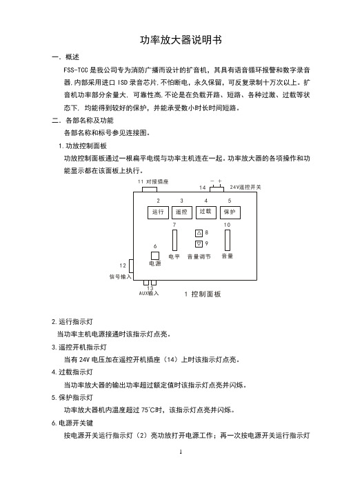
1.功放控制面板功放控制面板通过一根扁平电缆与功率主机连在一起。
功率放大器的各项操作和功能显示都在该面板上执行。
运行遥控过载保护2345电源电平音量调节音量678910-+24V遥控开关1411 对接插座信号输入121 控制面板A U X输入132.运行指示灯当功率主机电源接通时该指示灯点亮。
3.遥控开机指示灯当有24V电压加在遥控开机插座(14)上时该指示灯点亮。
4.过载指示灯当功率放大器的输出功率超过额定值时该指示灯点亮并闪烁。
5.保护指示灯功率放大器机内温度超过75℃时,该指示灯点亮并闪烁。
6.电源开关键按电源开关运行指示灯(2)亮功放打开电源工作;再一次按电源开关运行指示灯(2)灭功放关闭电源停止工作。
7. 输出电平指示指示输出电平的大小,0dB灯点亮输出电压为120V。
8. 音量向上调节键每按一次音量向上调节一档,音量指示(10)发光管就向上点亮一档。
9. 音量向下调节键每按一次音量向下调节一档,音量指示(10)发光管就向下灭一档。
10.音量指示指示音量调节的大小,满刻度为十档。
11.对接插座本功率放大器设计成控制和放大二大部件,通过对接插座和扁平电缆相连接而成一体。
12.信号输入插座0dB平衡信号输入端。
13.AUX输入插座CD或卡座不平衡信号输入端。
注意:该输入端是直接信号,没有优先级切换控制。
14. 遥控开机插座当有24V电压加在遥控开机插座上时,功放打开电源工作。
此时如按电源开关键(6)将不起作用。
15. 输出电平指示录放板输出电平指示,根据输出电平大小而点亮。
FST800-101S 液位压差式静力水准仪 产品说明书
液位压差式静力水准仪产品说明书(V1.0)湖南菲尔斯特传感器有限公司Hunan Firstrate Sensor Co.,Ltd●重要声明非常感谢您购买菲尔斯特产品,我们为您真诚服务到永远。
菲尔斯特追求卓越的品质,更注重优良的售后服务,如有需要请拔打:400-607-8500(7×24h)。
操作错误会缩短产品的寿命,降低其性能,严重时可能引起意外事故。
请您将本说明书交到最终用户手中,在产品使用前务必仔细熟读。
并请妥善保管好,以备需要时查阅。
本说明书仅供参考所用,具体产品外形以实物为准。
●产品概述FST800-101S液压式静力水准仪,也叫沉降监测静力水准仪,是一种高精密液位测量仪器,用于测量基础和建筑物各个测点的相对沉降。
由储液器、高精度芯体和特殊定制电路模块、保护罩等部件组成。
主要应用于综合管廊沉降监测。
广泛应用于大型建筑物、高层建筑物、大坝、水电站、核电站、水利枢纽工程、铁路、地铁、高铁、综合管廊等各测点不均匀沉降的测量。
●工作原理地基沉降是一个缓慢过程,在任何较短时期,反映到储液罐液面的变化都会非常细微,能否实时、精确地检测到这个微小变化,反映出地基的微小沉降,做到防微杜渐,是衡量一个静力水准仪产品好坏的关键,这对系统所集成液位传感器的实时性、精密性提出了极高要求。
由于是户外安装,液位传感器的温度系数、防水性、防雷击都是关键技术。
另外,静力水准仪整机的安装尺寸和易更换性也是重要的技术指标,加上储液罐、保护罩、调平支架、通联气、水管等部件组成。
液压式静力水准仪是基于连通器原理,通过测量若干个相互联通的安装于被测量点储液罐液位压力与测量基点(不动点)液罐液位压力的相对变化,反推出各个储液罐安装位置相对位置沉降变化量的一种精密仪器。
●应用领域3、隧道上部山体及建筑物;4、高速公路路基、边坡沉降检测;5、桥墩、基坑沉降检测;6、大坝及水利枢纽、高层建筑的基础;7、核电站、大型水电站;8、综合管廊沉降监测。
诺蒂菲尔FSB-200S红外线对射说明书

图 1 FSB-200S 智能红外光束感烟探测器
- 工作温度:-30℃~55℃ - 相对湿度:10%-93%,无凝结 - 外形尺寸:254mm × 191mm ×
84mm
附件
BEAMLRK:长距离反射镜附件(距离超过 70m 时需要)
本文不是以安装为目标。我们的产品 信息尽量做到最新最准确,我们无法 覆盖所有的具体应用或预见所有的需 求。参数的改变恕不通知。详细资料 请联系 -6886
FSB-200S
反射式红外光束感烟探测器
智能可编址设备
概述
对于使用环境温度范围宽(-30℃~ 55℃)、点型探测器安装维护困难的区 域,如车库、厂房、体育场馆、 大型仓 库等处,一般可采用红外光束感烟探测 器。NOTIFIER 的 FSB-200S 型探测器就 是为此而设计的。
2005.4.14
DN-6886
FSB-200S
反射式红外光束感烟探测器
智能可编址设备
BEAMMMK:安装附件(天花板或墙面安装, 可以增加调整角度)
BEAMSMK:表面安装附件
图 2 FSB-200S 安装示意图
图 2 FSB-200S 接线及功能示意图
本文不是以安装为目标。我们的产品 信息尽量做到最新最准确,我们无法 覆盖所有的具体应用或预见所有的需 求。参数的改变恕不通知。详细资料 请联系 NOTIFIER。
FSB-200S 型探测器为智能可编址反 射式红外光束感烟探测器,可直接接入 信号回路,占一个回路设备地址。该型 探测器红外线发射机和接受机合二为 一,单端接线,另一端仅是一个反射镜, 无需接线,从而极大地方便了现场布线。
特性
- 信号回路供电,无需附加电源
- 单端接线,直接接入信号回路 - 独立的报警、故障、正常状
诺帝菲尔 FSB-200产品说明书

FSB-200(A) and FSB-200S(A)Single-Ended, Reflector-TypeAddressable Beam Smoke DetectorDN-6985:C • H-212GENERALThe Notifier FSB-200 and FSB-200S are intelligent,addressable reflected beam smoke detectors for protectingopen areas with high and sloping ceilings, and wide-openareas, where spot-type smoke detectors are difficult to installand maintain. Ideal applications are atriums, cathedralceilings, aircraft hangars, warehouses, sporting arenas,concert halls, and enclosed parking facilities. They arecompatible with the NFS-3030, NFS2-3030, NFS-640, NFS2-640, and NFS-320 in FlashScan® or CLIP mode, as well aslegacy addressable panels. Installation of the single-endedreflective design is much quicker than a dual-ended projectedbeam detector. Alignment is easily accomplished with anoptical sight and a two-digit signal strength meter incorporatedinto the beam detector. Listed for operation from –22°F to131°F, the FSB-200 and FSB-200S are usable in open areaapplications where temperature extremes exceed the designlimits of other types of smoke detection.The FSB-200 and FSB-200S are a transmitter/receiver unitand a reflector. When smoke enters the area between the unitand the reflector it causes a reduction in the signal strength.When the smoke level (signal strength) reaches thepredetermined threshold, an alarm is activated. The detectorshave four standard sensitivity selections as well as twoAcclimate® settings. When either Acclimate® setting is selected, the detector’s advanced software algorithms automatically adjust to the optimum sensitivity for the specific environment.The FSB-200S has an integral sensitivity test feature of a filter attached to a servomotor inside the detector optics. Activation of the RTS151 or RTS151KEY remote test stations moves the filter into the pathway of the light beam, testing the detector’s sensitivity. This sensitivity test feature allows the user to quickly and easily meet the annual maintenance and test requirements of NFP A 72, without physical access to the detector. The servomotor must be powered by +24 VDC, not SLC power.FEATURES•Listed to UL 268, ULC CAN/ULC S529.•T ransmitter/receiver built into same unit.•Six user-selectable sensitivity levels.•16' to 328' (use BEAMLRK beyond 230') protection range.•Removable plug-in terminal blocks.•Digital display — no special tools required.•Built-in automatic gain control compensates for signal dete-rioration from dust buildup.•Optional remote test station.•Optional long-range kit (BEAMLRK) for applications in excess of 230' (70 m).•Optional multi-mount kit (BEAMMMK) providing ceiling or wall mount capability with increased angular adjustment.•Optional heater kits (BEAMHK and BEAMHKR) for prevention of condensation (not intended to increase orreduce the specified operating temperature).•Paintable cover.SPECIFICATIONSOPERATIONAL SPECIFICATIONSProtection Range: 16 to 230 feet (5 to 70 m), 230 to 328 feet (70 to 100 m) using optional BEAMLRK kit.Adjustment Angle: ±10° horizontal and vertical. Note that the optics move independently of the unit.Sensitivity (6 levels):NOTE: Sensitivity settings are a feature of specific control panels.•Level 1 — 25%.•Level 2 — 30%.•Level 3 — 40%.•Level 4 — 50%.•Acclimate® Level 5 — 30% to 50%.•Acclimate® Level 6 — 40% to 50%.Fault Condition (trouble):•96% or more obscuration blockage.•In alignment mode.•Improper initial alignment.•Self-compensation limit reached.Alignment Aid:•Optical gunsight.•Integral signal strength indication.•Two-digit display.Indicators:•Alarm — local red LED and remote alarm.•Trouble — local yellow LED and remote trouble.•Normal — local flashing green LED.FSB-200 withReflective PlateFSB-200 withBEAMMMK6975reflect.jpg6975beammk.jpgTest/reset features:•Integral sensitivity test filter (FSB-200S only, requires external power supply).•Sensitivity filter (incremental scale on reflector).•Local alarm test switch.•Local alarm reset switch.•Remote test and reset switch (compatible with RTS151 and RTS151KEY test stations).Smoke Detector Spacing: On smooth ceilings, 30 – 60 feet (9.1 to 18.3 m) between projected beams and not more than one-half that spacing between a projected beam and a sidewall. Other spacing may be used depending on ceiling height, airflow characteristics, and response requirements. See NFPA 72.ENVIRONMENTAL SPECIFICATIONS Temperature: –22°F to 131°F (–30°C to 55°C).Humidity: 10 – 93% RH noncondensing.ELECTRICAL SPECIFICATIONS •Voltage: 15 to 32 VDC.•Average Standby Current (24 VDC): 2 mA maximum (LED flashing, SLC @ 24 V).•Alarm Current (LED on): 8.5 mA maximum.•Trouble Current (LED on): 4.5 mA maximum.•Alignment Current: 20 mA maximum.•External Supply (FSB-200S only):Voltage — 15 to 32 VDCCurrent — 0.5 A maximum.•Remote Output (Alarm):Voltage - 15 to 32 VDC (Output voltage same as deviceinput voltage)Current - 15 mA maximum, 6 mA minimum (Output current is limited by 2.2K ohm resistor)•Heater Kit BEAMHK:Voltage - 15 to 32 V; Current - 92 mA maximum @ 32 V (heater only); Power Consumption -nominal 1.6 W @ 24 V, maximum 3.0 W @ 32 V.•Reflector Heater Kit BEAMHKR:Voltage - 15 to 32 V;Current - 450 mA maximum @ 32 V (per reflector); Power Consumption (per reflector) - nominal 7.7 W @ 24 V,maximum 15.0 W @ 32 V.MECHANICAL SPECIFICATIONSShipping Weight: 3.7 lbs (1.68 kg)Detector Dimensions: 10.0" H x 7.5" W x 3.3" D (254 mm H x 191 mm W x 84 mm D).Reflector Dimensions for 16' to 230' (5 to 70m) Applications: 7.9" x 9.1" (200 x 230 mm).Reflector Dimensions for Applications Beyond 230'/70m: 15.7" x 18.1" (400 x 460 mm).SENSITIVITY SELECTIONThe detector has six sensitivity selections (sensitivity settings are a feature of specific control panels). Each of these selections is only acceptable over a specific distance separation between the detector and the reflector per UL 268. The chart below determines which selections are acceptable for your installed distance. The sensitivity of the detector can be set only when the housing is removed and the detector is not in the fine adjustment step of the alignment mode, indicated by the illumination of the dual digital display. T o set the sensitivity, depress the sensitivity button one time. See Switch Locations diagram. Once the switch is pressed, the digital display will illuminate and read the current sensitivity setting in percent obscuration. To change the sensitivity, continue to depress the sensitivity switch until the desired setting is achieved. The digital display will turn off automatically if no further switch presses occur.In addition to the four standard sensitivity selections, the detector has two Acclimate® settings. When either Acclimate®setting is chosen the detector will automatically adjust its sensitivity using advanced software algorithms to select the optimum sensitivity for the environment. The sensitivity will be continuously adjusted within the ranges specified in the chart above.Total obscuration can be converted to percent per foot, assuming uniform smoke density for the entire length of the beam. The chart below converts total obscuration percent per foot for all acceptable sensitivity settings.SensitivitySettingPercentObscurationDisplayReadingAcceptableDISTANCEbetweenDetectorandReflector(ft)AcceptableDISTANCEbetweenDetectorandReflector(m) Level 125%2516.4 to 120 5.0 to 36.6 Level 230%3025 to 1507.6 to 45.7 Level 340%4060 to 22018.3 to 67 Level 450%5080 to 32824.4 to 100 Acclimate ®Level 130% to 50%A180 to 15024.4 to 45.7 Acclimate ®Level 240% to 50%A280 to 20024.4 to 67Table 1: Total ObscurationWiring Diagram with RTS151/KEYWiring Diagram6985graph.tif6985wirerts151.tif Alignment and Adjustment Locations6985adjloc.tif Housing Screw Locations6985screwlocs.tifPARTS LISTItem QuantityT ransmitter/Receiver Unit 1Paintable Trim Ring 1Reflector 1Plug-In Terminal Blocks 3Isolator Shunts 2Instruction Manual 1Orange Sticky Paper 1FSB-200/FSB-200SSee RTS151/KEY Installation Instructionsfor electrical ratings of the RTS151/KEYRTS151/KEYPin 1Pin 2Pin 4Pin 3Pin 5Remote Alarm OutAUX (-)Reset InputTest InputSee electricalratings.or Previousdevice.32 VDC MaximumTwisted pair isrecommendedDeviceAcclimate® Plus™ is a trademark of Honeywell International Inc.©2009 by Honeywell International Inc. All rights reserved. Unauthorized use of this document is strictly prohibited.This document is not intended to be used for installation purposes. We try to keep our product information up-to-date and accurate. We cannot cover all specific applications or anticipate all requirements.All specifications are subject to change without notice.For more information, contact Notifier. Phone: (203) 484-7161, FAX: (203) 484-7118.AGENCY LISTINGS AND APPROVALSThese listings and approvals apply to the devices specified in this document. In some cases, certain modules or applications may not be listed by certain approval agencies, or listing may be in process. Consult factory for latest listing status.•UL Listed: S2522 (FSB-200, FSB-200S)•ULC Listed: S2522 (FSB-200A, FSB-200SA)•CSFM: 7260-0028:228•MEA: 95-04-E•Maryland State Fire Marshal: Permit # 2167•FM ApprovedPRODUCT LINE INFORMATIONFSB-200: Intelligent beam smoke detector FSB-200A:Same as FSB-200 with ULC Listing.FSB-200S:Intelligent beam smoke detector with integral sen-sitivity test.FSB-200SA: Same as FSB-200S with ULC Listing.BEAMLRK: Long range accessory kit (required for applica-tions in excess of 230 ft/70 m).BEAMMMK:Multi-mount kit (provides ceiling or wall mount capability with increased angular adjustment).BEAMSMK: Surface-mount kit.RTS151: Remote test station.RTS151A: Same RTS151 with ULC listing.RTS151KEY: Remote test station with key lock.RTS151KEYA: Same as the RTS151KEY with ULC listing.BEAMHK: Heating kit for use with the transmitter/receiver unit of FSB-200S. For prevention of condensation.BEAMHKR: H eating kit for use with the reflector on FSB-200S. For prevention of condensation6500-MMK: Heavy-duty multi-mount kit for installations prone to vibration or where there is difficulty mounting the set angle.When installed with the transmitter/receiver unit, the 6500-SMK must be used as well.6500-SMK: Surface-mount kit (required when using 6500-MMK to mount transmitter/receiver).BEAMMMK(ceiling or wall mount kit sold sepa-rately)RTS151RTS151KEYBEAMHK6975b e a m m k .j p gr t s 151.w m frts151key.wmf6985hk.tif。
诺帝菲尔 302系列 说明书
302 SeriesRate-Anticipation Heat Detectorsdn-1271:A1 • I-307GeneralThe Thermotech 302 Series rate-anticipation heat detectorsoperate within a controlled range of two to three degrees oftheir set points, regardless of the speed or rate of temperaturerise. These detectors are available in either 135°F (57.2°C) or194°F (90°C) ratings.The 302 Series are normally-open devices designed espe-cially for fire detection and alarm systems.Features•Immediate response. The 302 Series activate wheneverambient air temperature reaches a detector’s setting, elimi-nating the thermal time lag inherent in conventional heatdetectors.•Eliminates false alarms. The 302 Series do not respondto momentary temperature fluctuations below the selectedtemperature.•Universal application. The 302 Series can be used in allareas for any type of occupancy.•Self-restoring.•Hermetically sealed. Shock resistant, corrosion resistant,and tamper-proof.Principles Of OperationThe 302 Series rate-anticipation heat detectors respond and activate the fire alarm immediately whenever the ambient tem-perature reaches the preset temperature setting. Under rapid heat rise conditions, the rate-anticipation feature enables the detector to respond one to three degrees ahead of the setting. At the same time, however, it does not respond to momentary temperatu re flu ctu ations below the selected protection level, thus eliminating false alarms. When temperature drops back down below the protection level, the detector au tomatically resets itself.Dimensions (Model 302)Total overall length: 4-1/8" (10.48 cm).Base diameter: 2" (5.08 cm).Electrical RatingsApplication Information302 Series detector have a smooth ceiling UL rating of 50' x 50' (15.24 x 15.24 meters) and are the only type of heat detec-tors having such a rating on both fixed temperature and rate anticipation. Agency Listings and ApprovalsThese listings and approvals apply to the modules specified in this document. In some cases, certain modules or applications may not be listed by certain approval agencies, or listing may be in process. Consult factory for latest listing status.•UL Listed: S539 (302-AW-135/-194; 302-ET-135/-194;302-135-194)•FM Approved: (302-AW-135/-194; 302-ET-135/-194;302-135/-194)•CSFM: 7270-0021:001Voltage Current 6 - 125 VDC 5 amps 6 - 25 VDC 1 amp 125 VDC0.5 amp1271pho1.jpgCut-Away View1271dia1.tifdn-1271:A1 • 12/23/08 — Page 1 of 2Page 2 of 2 — dn-1271:A1 • 12/23/08NOTIFIER® is a registered trademark of Honeywell International Inc.©2008 by Honeywell International Inc. All rights reserved. Unauthorized use of this document is strictly prohibited.This document is not intended to be used for installation purposes. We try to keep our product information up-to-date and accurate. We cannot cover all specific applications or anticipate all requirements.All specifications are subject to change without notice.For more information, contact Notifier. Phone: (203) 484-7161, FAX: (203) 484-7118.NOTE 1: For interior mounting in any atmosphere that is compatible with terminal-screw-type connections. UL rating 50' x 50' (15.24 x15.24 meters).NOTE 2: Hermetically sealed for moisture-proof or dust-proof installations. Requires no special backbox when the all-weather leads areproperly spliced to “THW” or equivalent type wire.NOTE 3: Hermetically sealed for moisture-proof or dust-proof installations. Requires no special backbox. Has plastic hexagonal wrenchgrip bushing with 1/2” (1.27 cm) conduit threads for attachment to threaded hub cover, or any outlet box.NOTE 4: Explosion-proof for installation in hazardous locations. Has hexagonal wrench-grip bushing with 1/2” (1.27 cm) conduit threadsfor attachment to threaded hub cover of Series JL fixture fitting as manufactured by Killark Electric Co., or equal.Thermotech Model 302 Series Rate-Anticipation Heat DetectorsModel NumberDescription Refer To302-135135°F Interior Vertical Mounting Note 1 below 302-194194°F Interior Vertical Mounting 302-AW-135135°F All-Weather Vertical Mounting Note 2 below 302-AW-194194°F All-Weather Vertical Mounting 302-ET-135135°F All-Weather Vertical Mounting Note 3 below 302-ET-194194°F All-Weather Vertical Mounting 302-EPM-135135°F Explosion Proof Mounting Note 4 below302-EPM-194194°F Explosion Proof MountingAP-PDecorative white plastic adaptor plate for mounting 302 and 302-AW to 4” outlet box.。
诺蒂菲尔NFS-3030中文安装手册
火灾报警控制器NFS-3030/E 安装手册目录第一章系统概述 (4)1.1 系统描述 (4)1.1.1 标准特性 (4)1.1.2 选件 (4)1.1.3 系统局限性 (4)1.2 系统部件 (5)1.3 产品图例 (5)1.3.1 主电源 (7)1.4 系统机箱 (7)第二章安装 (9)2.1 安装前的准备工作 (9)2.2 安装清单 (9)2.3 安装机箱 (10)2.4 安装机箱及底盘上的设备 (11)2.5 安装CPU板 (12)2.6 安装可选模块 (14)2.7 安装多线制线路模块 (15)2.7.1 概述 (15)2.7.2 安装扩展模块 (15)2.7.3 安装多层模块到底盘上 (16)2.7.4 连接多线制模块扁平电缆 (16)2.8 IZM-8RK/IZE-A触发设备线路 (18)2.8.1 非环形现场接线 (18)2.8.2 环形接线 (19)2.9 ICM-4RK/ICE-4告警输出线路 (19)2.9.1 ICM-4RK/ICE-4接线方式 (19)2.9.2 电源的连接 (20)2.10 CPU板上的“C”型继电器 (21)2.11 CRM-4RK/CRE-4上的“C”型继电器 (21)2.12 辅助继电器模块(ARM-4)上的“C”型继电器 (22)2.12.1 概述 (22)2.12.2 安装 (23)2.12.3 辅助继电器模块接线 (24)2.13 连接特殊的可选模块 (24)2.13.1 网络控制模块 (24)2.13.2 回路控制模块、回路扩展模块 (25)2.14 连接电源 (27)2.14.2 检查AC电源 (28)2.14.3 辅助电源连接 (29)2.15 UL功率限定接线要求 (29)2.16 安装打印机 (29)2.16.2 打印机安装顺序 (30)2.16.3 配置打印机 (30)2.17 信号回路接线(SLC) (32)2.18 连接编程PC机 (33)3 第三章释放应用 (34)3.1 概述 (34)3.2 编程 (34)3.3 接线 (34)3.3.1 连接释放设备到FCM-1模块 (34)3.3.2 连接NBG-12LRA急停释放按钮 (35)第四章系统测试 (37)4.1 验收测试 (37)4.2 定期测试及维护 (37)4.3 操作检测 (37)4.4 电池检测及维护 (38)附录A 电气参数 (39)A.1 工作电源 (39)A.2 SLC回路 (39)A.3 告警应用线路 (39)A.4 接线要求 (39)1 第一章系统概述1.1系统描述1.1.1标准特性●易于连接的1到10个回路●网络操作●VIEW TM早期报警火灾探测●FlashScan TM或CLIP协议探测器或模块●火警、故障、监控及安全继电器●支持32个告警器,每一个告警器64个或96个告警点●逻辑功能●多行显示●火警或预警能激活本地音响器或继电器●火警确认预警指示(NYC)●监控管道探测器●支持AWACS算法●EIA-485连接ACS告警器(包括LDM用户模拟图形显示器)●EIA-232连接打印机●自动编程特性可以快速编程新设备●易于连接到VeriFire 编程工具●系统电源可编址,充电器可为25AH到200AH的电池充电,并提供4.5A的电流给系统CPU●易于连接辅助电源及电池充电器,便于用户组成大的系统●诊断用LED指示灯及开关●接地故障检测●支持最大12个多线制线路模块,包括IZM-8RK输入模块1.1.2选件参阅1.2节“系统部件”各种可选模块的说明。
菲尔斯特FST600-204数显式温度变送器产品说明书
产品说明书(V1.0)湖南菲尔斯特传感器有限公司Hunan Firstrate Sensor Co.,Ltd非常感谢您购买菲尔斯特产品,我们为您真诚服务到永远。
菲尔斯特追求卓越的品质,更注重优良的售后服务,如有需要请拔打:400-607-8500(7×24h)。
操作错误会缩短产品的寿命,降低其性能,严重时可能引起意外事故。
请您将本说明书交到最终用户手中,在产品使用前务必仔细熟读。
并请妥善保管好,以备需要时查阅。
本说明书仅供参考所用,具体产品外形以实物为准。
●产品概述本公司生产的工业通用温度传感器是由热电阻(偶)与防护金属外壳组合而成,温度变送器是在传感器基础上增加变送转换功能,采用二、三线制信号输出方式,带有非线性校正电路,可直接测量工业过程中的液体、气体介质,安装简单,多种测温范围可选。
●产品特点1、安装简单,多种测温范围可选;2、高效防雷击、强抗射频和电磁干扰保护;3、反应速度快、精确度度高;4、长期稳定性好、低能耗、体积小;5、气液两用,与304不锈钢兼容的任何介质。
●技术指标量程-50~400℃注:温度超过120℃,需加隔离输出信号4~20mA精度±0.5%FS信号线规格2Wire供电电源15~30VDC 工作温度-40℃~+85℃储存温度-40℃~+125℃长期稳定性≤±0.1%FS/年测温元件PT100、PT1000响应时间T=50℃2.3s;T=90℃5.4s 耐压典型(40bar)外壳材质304不锈钢介质兼容性与304不锈钢兼容的各种介质安装螺纹M20X1.5、G1/4、NPT1/4或按要求定制电气连接赫斯曼带显示防护等级IP65●电气接口及接线方法●注意事项1、安装时请注意安装方式,安装是否匹配,扳手只可套接在六方接口处进行安装,严禁套在产品外管及尾接头处安装;2、使用时注意线路连接可靠,连线方式正确,产品电缆线请勿用力拉扯,以免损坏产品内部结构;3、严禁产品超量程使用,产品出现异常,请停机检查;4-20mA 2-Wire 1+Vcc Red2+lout Black4、传感(变送)器的运输、安装、使用过程中不可随意摔放,避免损坏;5、产品保修期为一年,非用户使用不当造成的损坏保修包换;6、传感(变送)器应存放在通风良好、无酸、无碱、无腐蚀性气体的库房,环境温度-20℃~+60℃,相对湿度小于95%RH。
菲布尔+福斯 Ultrasonic 传感器 UC4000-L2-U-V15 产品说明书
Ultrasonic sensorUC4000-L2-U-V15R e l e a s e d a t e : 2016-04-25 09:24D a t e o f i s s u e : 2016-04-25188204_e n g .x m lDimensionsElectrical ConnectionPinoutLED yeLED gn LED ye LED gn 37M 12 x 12867402030405.5ø 5.54660To u tp w r401+U B524-U B3Program input Analog output Synchronization 134521 BN2 WH3 BU4 BK 5GYWire colors in accordance with EN 60947-5-2(brown)(white)(blue)(black)(gray)R e l e a s e d a t e : 2016-04-25 09:24D a t e o f i s s u e : 2016-04-25188204_e n g .x m lDescription of Sensor FunctionsProgramming the sensor functionsThe sensor features an analog output with two programmable limit values. The limit values and output operating modes can be programmed in three different ways:- Using the programming key on the sensor- By activating the 0-V or +U B supply voltage on the programming input (for programming the limit values only)- Using the serial interface on the sensor. This method requires an external interface module.The programming methods using the programming key and programming input are described below. To use the serial interface on the sensor for programming, see the software description. The processes for programming the limit values and the sensor operating modes run completely independently and do not influence one another.Notes:-The sensor can only be programmed during the first 5 minutes after switching on. This time is extended during the actual programming pro-cess. The option of programming the sensor is revoked if no programming activities take place for 5 minutes.-Programming can be aborted at any time during the process, without changing the sensor settings. To do so, press and hold the program-ming key for 10 seconds.Programming the limit value of the analog characteristicNoteA flashing red LED during the programming process indicates unreliable object detection. Should this occur, correct the alignment of the object until the yellow LED flashes. Only then will the settings be transferred to the sensor memory.Programming the limit values using the programming keyProgramming the near characteristic limit value1.Position the object at the site of the required near limit value2.Press and hold the programming key for 2seconds (yellow LED flashes)3.Briefly press the programming key (green LED flashes 3 times as confirmation). The sensor returns to normal mode.Programming the distant characteristic limit value1.Position the object at the site of the required distant limit value2.Press and hold the programming key for 2seconds (yellow LED flashes)3.Press and hold the programming key for 2seconds (green LED flashes 3 times as confirmation). The sensor returns to normal mode.Programming the limit values using the programming inputNotes:-Before starting the programming process, the programming input must be disconnected for at least 2seconds.-If the operating voltage (0 V or +U B ) is applied for >10seconds, the sensor returns to normal mode without changing the settings. To ensure that programming is successful, disconnect the programming input before this time elapses.-If the programming input is not used, it should be permanently connected at 0V.-If programming adapter UB-PROG2 is used for the programming process, the "A1" key is equivalent to 0V and "A2" to +U B . In this case,ensure that the wire that is connected to the programming input is open at the end of the sensor cable (not clamped at potential).Programming the near characteristic limit value1.Position the object at the site of the required near limit value2.Connect the programming input to 0V for 2seconds (yellow LED flashes, then the green LED flashes three times as confirmation). The sen-sor then returns to normal mode.Programming the distant characteristic limit value1.Position the object at the site of the required distant limit value2.Connect the programming input to +U B for 2seconds (yellow LED flashes, then the green LED flashes three times as confirmation). The sensor then returns to normal mode.Programming the sensor operating modesThe sensor features a two-stage process for programming the sensor operating modes. During this process, you can program:1.The curve of the analog characteristic 2.The shape of the sound coneThese two stages of the process are programmed in succession. To switch from one programming function to the next, press and hold the pro-gramming key for 2seconds.Press and hold the programming key for 5seconds to switch to the process for programming the sensor operating modes.Programming adapter PACTware 3.6FDT Framework PACTware 4.X FDT FrameworkUltraschall-Sensoren DTMDTM devices for communication with cube style and UMC... sensors V15-G-2M-PVCFemale cordset, M12, 5-pin, PVC cable UB-PROG2Programming unit Microsoft .NETR e l e a s e d a t e : 2016-04-25 09:24D a t e o f i s s u e : 2016-04-25188204_e n g .x m l Programming the curve of the analog characteristic1.The green LED is now flashing. The number of flashes indicates the output function currently programmed:1x: rising ramp 2x: falling ramp 3x: zero-point line2.Briefly press the programming key to switch between the different curves and press again to select the required curve.3.Press and hold the programming key for 2seconds to save the selection and switch to the process for programming the sound cone.Programming the shape of the sound cone1.The red LED is now flashing. The number of flashes indicates the sound cone shape currently programmed:1x: narrow 2x: medium 3x: wide2.Briefly press the programming key to navigate through the different sound cone shapes in succession and press again to select the required sound cone shape.3.Press and hold the programming key for 2seconds to save the selection and return to normal mode.Reset Sensor to Factory SettingsThe sensor has a feature to reset to factory settings 1.Disconnect the sensor from power supply 2.Press and hold the Programming Button3.Connect Sensor to power supply (yellow and red LED flash simultaneously for 5s then yellow and green LED flash simultaneously)4.Release Programming ButtonThe sensor now operates with default factory settings.Factory settingsSee technical data.IndicatorsThe sensor features three LEDs for indicating statuses.SynchronizationThis sensor features a synchronization input for suppressing ultrasonic mutual interference ("cross talk"). If this input is not connected, the sensor will operate freewheeling using internally generated clock pulses. It can be synchronized by applying an external square wave or by means of appropriate programming via the serial interface. Each falling edge of the synchronization pulse triggers transmission of a single ultrasonic pulse. If the synchronization signal remains low for ≥ 1 second, the sensor will revert to normal operating mode. Normal operating mode can also be activated by opening the signal connection to the synchronization input.(See note below)If the synchronization input goes to a high level for > 1 second, the sensor will switch to standby mode, indicated by the green LED. In this mode, the output(s) will remain in the last valid output state. When using the external synchronization feature, please refer to the software description.Note:If the option for synchronization is not used, the synchronization input has to be connected to ground (0V) or the sensor has to be operated via a V1 cordset (4-pin).The synchronization function cannot be activated during programming mode and vice versa.The following synchronization modes are possible:1.Several sensors (max. number see technical data) can be synchronized together by interconnecting their respective synchronization inputs. In this case, each sensor alternately transmits ultrasonic pulses in a self multiplexing mode. No two sensors will transmit pulses at the same time. (See note below)2.Several sensors (max. number see technical data) can be synchronized together by interconnecting their respective synchronization inputs. Due to programming via the sensors interface one sensor acts as a master device, all the others as slave devices. (see description of the interface) In this master / slave mode the sensors are triggered in parallel and are synchronized by a common synchronization pulse, provided by the master device.3.Multiple sensors can be controlled by the same external synchronization signal. In this mode the sensors are triggered in parallel and are synchronized by a common external synchronization pulse. All sensors must be parameterized for external synchronization by means of the sensor interface. See software description.4. A separate synchronization pulse can be sent to each individual sensor. In this mode the sensors operate in external multiplex mode. (See note below). All sensors must be parameterized for external synchronization by means of the sensor interface. See software description.5. A high level (+U B ) or a low level (-U B )on the synchronization input switches the sensor to standby mode if it is parameterized for external synchronization.Note:Sensor response times will increase proportionally to the number of sensors that are in the synchronization string. This is a result of the multiplexing of the ultrasonic transmit and receive signal and the resulting increase in the measurement cycle time.Note:The sensors syncronization input delivers an output current in case of low level and burdens with its input impedance in case of high level. Please pay attention that the syn-chronizing device needs to have that driver capability:driver current against +U B ≥ n * high-level/input impedance (n = number of sensors to be synchronized)driver current against 0V ≥ n * output current (n = number of sensors to be synchronized).Green LEDYellow LED Red LED In normal mode Fault-free function Fault (e.g. compressed air)On Off Object in the analog characteristic range retains previous sta-tusOff On When programming the limit values Object detected No object detectedConfirmation of successful programming Warning in the event of invalid programming Off Off Flashing 3xOff Flashing Off Off Off Off Flashing Off Flashing 3x When programming the operating mode Programming the output function Programming the sound coneFlashing OffOff OffOff Flashing。
- 1、下载文档前请自行甄别文档内容的完整性,平台不提供额外的编辑、内容补充、找答案等附加服务。
- 2、"仅部分预览"的文档,不可在线预览部分如存在完整性等问题,可反馈申请退款(可完整预览的文档不适用该条件!)。
- 3、如文档侵犯您的权益,请联系客服反馈,我们会尽快为您处理(人工客服工作时间:9:00-18:30)。
功率放大器说明书
一.概述
FSS-TCC是我公司专为消防广播而设计的扩音机,其具有语音循环报警和数字录音器,内部采用进口ISD录音芯片,不怕断电,永久保留,可反复录制十万次以上。
扩音机功率部分余量大, 可靠性高,不论是在负载开路、短路、各种过激、过载等状态下, 均能得到较好的保护,并能承受数小时长时间短路。
二.各部名称及功能
各部名称和标号参见连接图。
1.功放控制面板
功放控制面板通过一根扁平电缆与功率主机连在一起。
功率放大器的各项操作和功能显示都在该面板上执行。
运行遥控过载保护
2345
电源电平音量调节音量
67
8
9
10
-+
24V遥控开关
14
11 对接插座
信号输入
12
1 控制面板
A U X输入
13
2.运行指示灯
当功率主机电源接通时该指示灯点亮。
3.遥控开机指示灯
当有24V电压加在遥控开机插座(14)上时该指示灯点亮。
4.过载指示灯
当功率放大器的输出功率超过额定值时该指示灯点亮并闪烁。
5.保护指示灯
功率放大器机内温度超过75℃时,该指示灯点亮并闪烁。
6.电源开关键
按电源开关运行指示灯(2)亮功放打开电源工作;再一次按电源开关运行指示灯
(2)灭功放关闭电源停止工作。
7. 输出电平指示
指示输出电平的大小,0dB灯点亮输出电压为120V。
8. 音量向上调节键
每按一次音量向上调节一档,音量指示(10)发光管就向上点亮一档。
9. 音量向下调节键
每按一次音量向下调节一档,音量指示(10)发光管就向下灭一档。
10.音量指示
指示音量调节的大小,满刻度为十档。
11.对接插座
本功率放大器设计成控制和放大二大部件,通过对接插座和扁平电缆相连接而成一体。
12.信号输入插座
0dB平衡信号输入端。
13.AUX输入插座
CD或卡座不平衡信号输入端。
注意:该输入端是直接信号,没有优先级切换控制。
14. 遥控开机插座
当有24V电压加在遥控开机插座上时,功放打开电源工作。
此时如按电源开关键(6)将不起作用。
15. 输出电平指示
录放板输出电平指示,根据输出电平大小而点亮。
16.录音指示
录放板处于录音状态时该指示灯点亮。
17.放音指示
录放板处于放音状态时该指示灯点亮。
18.运行指示
按下电源开关键(21)时该指示灯点亮。
19.录音键
按下该键后录放板就录制话筒和AUX输入的信号并存储在第1段中。
注意:本录放板专为消防扩声而设计,用户不可随意按动录音键,否则会误擦掉已录制的信息。
20.放音键
按下该键后录放板就播放存储在第1段中的信息,直到结束或再按一下该键后停
止。
21. 电源开关键
录放板电源开关键。
22.监听音量调节旋钮
调节监听录放板输出信号音量大小。
注意:用话筒播音时要将监听音量调节旋钮调到合适位置,否则将引起啸叫。
23. 遥控插座
当有24V 电压加在遥控插座上时,录放板将播放存储在第0段中的信息。
播音优先级为1。
24.预录开关
按下该键后录放板就准备录制第0段信息。
注意:同样用户不可随意按动预录开关,否则会误擦掉已录制的信息。
25. AUX 输入插座
CD 或卡座不平衡信号输入端。
播音优先级最低,优先级为2。
26.信号输出插座
0dB 平衡信号输出端。
该输出端是话筒输入(29)、 AUX 输入(25)和电子芯片放音三种信号混合输出端,并根据优先级切换输出。
27.电源输入插座
录放板24V 电源输入端。
28.录放板
报警信号和现场指挥信号电子芯片录放器。
被录制好的信息可长期保存,不怕断电。
源输入
9
筒输入
26
25
24
预录开关27
23
28 录放板
29.话筒输入插座
话筒输入也是紧急广播输入口,具有播音最高优先级,优先级为0。
30.功率放大器
功率放大器主机。
31.对接插座
通过扁平电缆与功放控制面板对接。
32.线路输出插座
线路输出插座专为功率扩展之用。
33.功率放大器输出端
功率放大器功率通过该接线柱被送出,输出电压为70V、100V、120V三挡。
三.使用
1.按连接图连接录放板和功放的各插头接线,并接通电源。
录放板和功放接通电源后处于待机状态。
2.根据需要连接其他信源到录放板的AUX输入插座上。
3.根据需要按音量调节键上(8)下(9)键,调节功率放大器的输出电平大小。
要注意功率放大器的输出电平大小的变化,如果信号太大要引入失真,严重时会损坏功率放大器。
4.录制第0段信息
按下预录开关(24)接着按录音键(19)录放板就可以录制话筒(29)和AUX输入(25)的信号并存储在第0段中,直到电子芯片尾结束或按再一下录音键后停止。
在录制第0段信息时,录音指示灯(16)闪烁。
用户可根据自己物业的特点,预录上适合自己使用的内容。
注意:录制完第0段信息后,要再按一下预录开关使录放板退出预录状态,否则录放板将不进行其他功能操作。
要监听第0段内容,只要将24V电压加在遥控插座(23)上即可。
5.录制第1段信息
第1段处于第0段之后直到电子芯片尾。
按下录音键后录放板就录制话筒和AUX输入的信号并存储在第1段中,直到电子芯片尾结束或再按一下该键后停止。
在录制第1段信息时,录音指示灯(16)长亮。
6.放音操作
按放音键(20)这时放音指示灯(17)亮,表示录放板处于放音状态而且正在播放第1段内容,直到第1段内容放完为止。
中途要停止放音只要再按一下放音键(20)即可。
注意:每次只能从第1段的开始放音。
四、主要性能指标:
五、备附件:
1. 使用说明书1份
2.保险丝3A 1根
3.插头Φ6.35 1只
4.26芯扁平对接线1根附:连接图。