RefractoMax521示差检测器说明书
热重差热荧光联用仪使用方法说明书

热重差热荧光联用仪使用方法说明书一、简介热重差热荧光联用仪(以下简称热重差仪)是一种集热重分析和热荧光分析功能于一体的仪器。
它能够同时实时监测材料的重量变化和热分解过程中的气体释放情况,为研究材料的热性能提供重要数据支持。
二、使用前准备1. 确认仪器是否处于正常工作状态,包括电源连接是否良好、仪器表面是否清洁、温度传感器是否校准准确等。
2. 准备好所需样品,确保样品干燥,并根据实验要求确定样品的质量范围。
3. 准备好相关试剂和标准物质。
三、仪器操作步骤1. 打开电源开关,待仪器启动完成后,仪器进入待机状态。
2. 打开电脑,确保与热重差仪连接的软件已经安装且界面正常显示。
3. 将待测试的样品装入热重差分析仪样品盘中,并将样品盘放入样品架中固定好。
4. 在软件界面上点击"新建实验",设置实验参数,包括样品信息、实验温度范围、升温速率等。
根据样品特性和实验目的进行合理的参数设定。
5. 点击"开始实验",仪器开始进行升温和热重差和热荧光联用分析过程。
实时检测并记录样品的重量变化和热荧光信号。
6. 实验完成后,点击"结束实验",关闭实验界面。
7. 将样品从样品盘中取出,清理空置的样品架和样品盘,保持仪器的整洁。
四、实验数据分析1. 在仪器软件中,通过选择"查看数据"可以查看实时获取的数据,并可导出数据文件以备进一步分析处理。
2. 利用专业数据处理软件,对实验数据进行曲线拟合、峰值分析、质量损失计算等操作,获取材料的热重性能数据。
3. 将荧光信号与重量变化数据进行对比分析,研究样品的热解、失水过程中可能释放的气体成分及其释放动力学等信息。
五、操作注意事项1. 避免样品中含有水分或其他可挥发物质,以免影响实验结果。
2. 样品装填要均匀、适量,避免过填或不填满。
3. 注意操作过程中的安全问题,尤其是在高温实验时要注意防火防爆。
4. 在实验数据分析中,要规避计量单位错误、曲线拟合不准确等问题,保证数据分析的可靠性。
Waters 2414示差检测器中文说明书

WatersHPLC SystemBasic Teaching Material For 2414 Refractive Index Detector 沃特斯高效能液相層析系統-2414折射率偵測器基礎操作指引文案大全Content一、儀器介紹與功能說明 (3)1. 儀器外觀 (3)2. 螢幕說明 (3)二、開機方法 (4)三、操作畫面說明 (4)四、溫度設定 (6)五、IEEE 位址 ( IEEE Address ) 設定 (7)六、液晶螢幕明暗度設定 (8)七、關機方法: (8)一、 儀器介紹與功能說明1. 儀器外觀2. 螢幕說明a. RIU Modeb. 410 Mode液晶顯示幕操作面板二、開機方法a.將2414 RI Detector的電源開關打開至ON(1)的位置,機器開始作自我檢查。
b.待儀器自我測試完畢後,即出現以下畫面,此乃表示開機測試正常。
三、操作畫面說明液晶顯示幕四、溫度設定a.按溫度設定鍵。
液晶顯示幕b.進入溫度設定畫面。
c.按<▲>/<▼>至Detector(Det)或Column(Col) 溫度設定位置(Set)。
d.輸入預設定之溫度大小。
e.按<HOME>鍵回復至初始畫面。
五、IEEE 位址 ( IEEE ADDRESS ) 設定a.按<HOME>鍵回復至初始畫面。
液晶顯示b.按<Shift>及<CONFIGURE>鍵,至系統設定功能。
c.將游標移動至IEEE位址設定位置,輸入適當之位址編號。
( 位址編號不能與其他儀器/設備相同 )d.設定完畢後,按<HOME>鍵回復至初始畫面。
六、液晶螢幕明暗度設定a.按<HOME>鍵回復至初始畫面。
液晶顯示b.按<Shift>及<Contrast>鍵,至螢幕明按度設定功能。
c.按<▲>/<▼>調整螢幕適合之明暗度。
高效液相色谱法测定葡萄糖光催化氧化产物
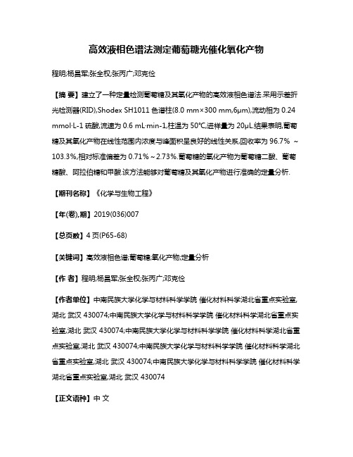
高效液相色谱法测定葡萄糖光催化氧化产物程明;杨昌军;张全权;张丙广;邓克俭【摘要】建立了一种定量检测葡萄糖及其氧化产物的高效液相色谱法.采用示差折光检测器(RID),Shodex SH1011色谱柱(8.0 mm×300 mm,6μm),流动相为0.24 mmol·L-1硫酸,流速为0.6 mL·min-1,柱温为50℃,进样量为20μL.结果表明,葡萄糖及其氧化产物在线性范围内浓度与峰面积呈良好的线性关系,回收率为96.7%~103.3%,相对标准偏差为0.71%~2.73%.葡萄糖的氧化产物为葡萄糖二酸、葡萄糖酸、阿拉伯糖和甲酸.该方法能够对葡萄糖及其氧化产物进行准确的定量分析.【期刊名称】《化学与生物工程》【年(卷),期】2019(036)007【总页数】4页(P65-68)【关键词】高效液相色谱;葡萄糖;氧化产物;定量分析【作者】程明;杨昌军;张全权;张丙广;邓克俭【作者单位】中南民族大学化学与材料科学学院催化材料科学湖北省重点实验室,湖北武汉 430074;中南民族大学化学与材料科学学院催化材料科学湖北省重点实验室,湖北武汉 430074;中南民族大学化学与材料科学学院催化材料科学湖北省重点实验室,湖北武汉 430074;中南民族大学化学与材料科学学院催化材料科学湖北省重点实验室,湖北武汉 430074;中南民族大学化学与材料科学学院催化材料科学湖北省重点实验室,湖北武汉 430074【正文语种】中文【中图分类】O657.72葡萄糖是自然界中含量最多且分布最广泛的一种单糖,是生产生物燃料和平台化学品的理想原料[1-3]。
氧化葡萄糖可以得到多种高附加值的化学品,如葡萄糖二酸、葡萄糖酸、阿拉伯糖、乳酸、甘油、草酸、乙酸和甲酸等[4-6]。
其中葡萄糖二酸、葡萄糖酸和乳酸是食品工业和医药领域的重要添加剂和中间体,此外,葡萄糖二酸具有两端均为羧基的特殊结构,被认为是可以替代化石原料合成聚合物的单体;甘油、草酸和甲酸是化工生产中的重要原料和助剂[7-10]。
高效液相Waters 2410操作指南
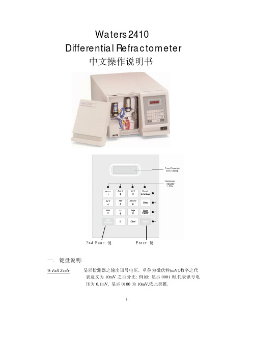
1Waters 2410Differential Refractometer 中文操作说明书2n d F u n c 键 E n t e r 键一. 键盘说明: % Full Scale 显示检测器之输出讯号电压,单位为微伏特(mV),数字之代 表意义为10mV 之百分比; 例如: 显示0001时,代表讯号电 压为0.1mV, 显示0100为10mV,依此类推.Sens设定检测器之感度,连续按压此键可从1-1024以2的次方数来设定,最灵敏为1024,最不灵敏为1,设定完毕后再按Enter键.Scale Factor设定检测器之感度(Sens)的百分比,此设定只对10mV(Rec)输出端子之传统记录器有作用,对1V(Int)输出端子之积分器或以IEEE-488讯号输出者,并无作用.Enter输入值确认键.Clear 清除错误的输入值.2nd Func转换键盘至第二操作功能.2nd 功能键:Ext 1 ℃显示第一号外接式分离管柱加热装置之温度数值(可设定温度范围为室温至150℃),若出现”245.7”,即表示无连接加热装置Ext 2 ℃显示第二号外接式分离管柱加热装置之温度数值(可设定温度范围为室温至150℃),若出现”245.7”,即表示无连接加热装置Int ℃显示检测器内部侦测槽加热装置之温度数值(可设定温度范围为30℃至150℃).Remote当检测器处于被控制状态(例如以IEEE-488联机),此指示灯会亮起.Set ℃设定所有加热装置之温度数值,建议最少设定值须高于室温5℃,以求稳定.Filter设定时间常数(Time Constant)以改善基在线之噪声,连续按压此键可设定值为0.2 ,1.0 ,3.0 ,10.0 秒.Auto Zero设定检测器讯号自动归零.Mark在层析图谱上作记号,但只对10mV输出之传统记录器有作用, 并不影响积分器或软件计算机之输出信号.+/-改变检测器输出讯号之正负方向,内设在正向之位置.Purge以移动相冲洗参考液槽使与样品液槽之溶剂组成一致,当设定冲洗状态时,屏幕会出现”PgE”字样; 再按一次此键,即解除冲洗状态.23Waters 2410 Refractometer Fluidic Paths二. 操作说明1. 打开电源开关至ON(1)的位置,机器开始作自我检查,注意是否有任何故障讯息出现.2. LED 屏幕上出现之数字意义是代表相对于下方键盘周围红色小灯号所亮起之功能键数值.3. 设定内部侦测槽温控: 按一下2nd Func 键⇒再按3键,屏幕会出现目前之 温度数值; 按一下2nd Func 键⇒再按4键⇒紧接着输入温度数值⇒Enter. 通常此温度数值须设定比室温高5℃(约35℃).4. 设定外接式分离管柱加热装置温控: 按一下2nd Func 键⇒再按1键,屏幕会出现目前之温度数值; 按一下2nd Func 键⇒再按4键⇒紧接着输入温度数值⇒Enter.建议温度: THF (40℃) Toluene (75℃)D M F (85℃) W a t e r (40℃)5. 设定Sens 至4或8之感度,有必要的话再提升感度.6. 按一下% Full Scale 键,使屏幕显示检测器输出讯号电压.7. 等HPLC 或GPC 系统平衡稳定后,按一下2nd Func 键⇒再按9键,以移动相冲洗参考液槽,冲洗约10分钟后,按一下2nd Func 键⇒再按9键,以解除冲洗状态,等待约1至2分钟后,看屏幕讯号数值是否已固定不变; 若讯号数值仍跳动不稳,则继续做Purge.8. 若基线讯号稳定,于注入检体前,按一下2nd Func 键⇒再按6键,使检测器自动归零,再开始进样.9.每次更换移动相后,等HPLC或GPC系统平衡稳定后,请重复7至8步骤,再开始做分析检测.※注意事项:<1>. 建议于做分析检测前,至少有让检测器热机达24小时以上; 因此平常待机时,无须关机,只要降低Pump流速至0.1ml/min,使其继续保持平衡稳定即可.<2>. 当使用水性塩类移动相后,需以超纯水冲洗,再以甲醇冲洗.<3>. RI检测器之样品侦测槽最高耐压值为100psi,请注意流速与出口管路所造成之逆压不得超过此上限值,否则将造成侦测槽破损.<4>. 若此检测器是以IEEE-488联机做计算机控制时,以上之操作条件参数必须在Millennium 32计算机软件操作方法内加以储存设定,才得以作有效之控制.三. 关机方法:1.直接关闭电源开关至OFF(0)的位置即可.2.所有的输入设定值将被保持至下次开机时.4。
智能液体检测器完全配套套装说明书

HUB8INSTRUCTION MANUALENGLISHSmart Refrigerant Complete Kit • email: ****************TABLE OF CONTENTSImportant Safety Warnings (3)Symbols (4)WHP1 Overview (5)WPP1 Overview (6)WPC2 Overview (7)WOT2 Overview (8)WVG2 Overview (9)APP Overview ....................................10-16 Refrigerant Side ................................10-11Air Side (12)Vacuum Side ...................................13-14Unit Screen (15)User Info Screen (15)Support Screen (16)FCC/IC Information ................................17- 18Disposal. . . . . . . . . . . . . . . . . . . . . . . . . . . . . . . . . . . . . . . . . . . . .19Cleaning (19)Storage (19)Warranty (20)2IMPORTANT SAFETY WARNINGSWARNINGRead entire Safety Notes section regarding potential hazard and proper instructions before using these probes. In this manual the word “WARNING” is used to indicate conditions or actions that may pose physical hazards to the user. The word “CAUTION” is used to indicate conditions or actions that may damage the instruments.WARNINGTo ensure safe operation and service of these probes, follow these instructions. Failure to observe these warnings can result in severe injury or death.WARNINGNot exceed the following maximum pressure limits.WVG2 Vacuum Gauge maximum over pressure 700 psi.WPP1 Pressure Gauge maximum over pressure 1000 psi.WARNING• Do not open these probes to replace batteries while the probes are connected.• To avoid false readings, replace batteries if a low battery indicator appears.• Do not use these probes if they appear damaged.• Always adhere to national and local safety codes. Use proper personal protective equipment (PPE).WARNINGThese probes are designed for trade professionals who are familiar with the hazards of their trade.Observe all recommended safety procedures that include proper lockout utilization and use of personal protective equipment that includes safety glasses, gloves and flame resistant clothing.3SYMBOLS Phone Web Manual PinFavoritesConnection StrengthWHP1WPP1WPC2WOT2WVG2 Battery levelHomeUnitsTool BoxUserSupport Refrigerant Tank45WHP1 (Hygrometer) OverviewGENERAL SPECIFICATIONSTemperature Range: 14° to 158°F (-10° to 70°C)Temperature Accuracy: ±0.5˚F (0.3˚C)Relative Humidity Range: 14° to 140°F (-10° to 60°C)Relative Humidity Resolution: 30% to 85% RH Relative Humidity Accuracy: ±3% 20% to 80% otherwise ±5%Operating Temperature: 14° to 158°F (-10° to 70°C)Storage Temperature: 13° to 185°F (-25° to 85°C)Operating Humidity: 20% RH to 80% RH Dimensions: 6.84 in x 1.93 in x 1.53 in (17.4 cm x 4.9 cm x 3.9 cm)Item Weight: 4.4 oz (125 g)Certification: CE Conformity, FCC/IC Battery Type: (AAA) 2Battery Life: 100+ hoursLock Button: Press to open or close probe Pressing the lock button and opening the probepowers it on1/4” diameter probe Magnetic Mount Battery CoverLight: Blinks GREEN when probe is powered on. Blinks RED when low battery*Press down Lock Button to release probe. Low battery indicator is also in the Remove battery cover.Replace the old batteries with 2 new (AAA) batteries.Replace the battery cover.Caution : Take care not to lose the screws when6WPP1 (Pressure Probe) OverviewGENERAL SPECIFICATIONS• Range: 0 to 725 PSIg • Resolution: 0.1 PSI• Accuracy: 0.5% F.S. (at 25˚C ±3˚C) Total 1% F.S. 32˚ to 158˚F (0˚ to 70˚C)• Operating Temperature: 14° to 158°F (-10° to 70°C)• Storage Temperature: 13° to 185°F (-25° to 85°C)• Operating Humidity: 30% RH to 85% RH • Over-range: 1000 PSI• Dimensions: 6.70 in x 1.56 in x 1.44 in (17 cm x 4 cm x 3.7 cm)• Item Weight: 7.4 oz (210 g)• Certification: CE Conformity, FCC/IC • Battery Type: (AA) 2•Battery Life: 100+ hoursA. Battery coverB. Light: Blinks GREEN when probe is powered on and blinks RED when low battery.*C. Power Button: Hold for one second to power onD. 1/4”pressure connectorE. 1/4” pass-through connectorCaution : Max over pressure is 1000 PSI* NOTE: Low battery indicator is also in the “Tool Connection” screen of the app.• Remove battery cover.• Replace the old batteries with 2 new (AA) batteries.• Replace the battery cover.Battery level displayed in the tool connection screen to the right of each probe connected.Caution : Take care not to lose the screws when opening battery compartments7WPC2 (Pipe Clamp Sensor) OverviewGENERAL SPECIFICATIONS• Range: 32˚ to 176˚F (0˚ to 80˚C)• Resolution: 0.1˚F• Accuracy: ±(0.6˚F (0.3˚C))• Response Time: <30 sec.• Operating Temperature: 14° to 158°F (-10° to 70°C)•Storage Temperature: 13° to 185°F (-25° to 85°C)Dimensions: 5.66 in x 3.81 in x 1.10 in (14.4 cm x 9.7 cm x 2.8 cm)• Item Weight: 2.1 oz (60 g)• Jaw Opening: Maximum pipe diameter is 1.5 in. (3.8cm)• Certification: CE Conformity, FCC/IC • Battery Type: (AA) 1• Battery Life: 100+ hoursA. Light: Blinks GREEN when probe is powered on and blinks RED when low battery. *Opening the clamp powers it onB.Temperature sensor* NOTE: Low battery indicator is also in the “Tool Connection”screen of the app.• Remove battery cover.• Replace the old batteries with 1 new (AA) battery.• Replace the battery cover.Caution : Take care not to lose the screws when opening battery compartments8WOT2 (Outside Teperature Sensor) OverviewGENERAL SPECIFICATIONS• Range: 32° to 180°F (0° to 82°C)• Resolution: 0.1”• Accuracy: ± 2°F (1°C)• Operating Temperature: 14° to 158°F (-10° to 70°C)• Storage Temperature: 13° to 185°F (-25° to 85°C)• Operating Humidity: 30% to 85% RH • Dimensions: 4.75 in x 2.37 in x 1.5 in • Item Weight: 5.4 oz (153 g)• Certification: FCC/IC, CE Comformity • Battery Type: (AA) 2• Battery Life: 100+ hoursA. Light: Blinks GREEN when probe is powered on and blinks RED when low battery.*B. Temperature SensorC.Magnetic Hanger Strap* NOTE: Low battery indicator is also in the “Tool Connection” screen of the app.• Remove battery cover.• Replace the old batteries with 2 new (AA) battery.•Replace the battery cover.9WVG2 (Vacuum Gauge) OverviewGENERAL SPECIFICATIONS• Range: 0 - 20,000 Microns • Resolution: 1 micron• Accuracy: ±5% rdg ±5 microns• Operating Temperature: 14° to 158°F (-10° to 70°C)• Storage Temperature: 13° to 185°F (-25° to 85°C)• Operating Humidity: 30% to 85% RH • Dimensions: 5.6 in x 2.37 in x 1.5 in • Item Weight: 4.2 oz (119 g)• Certification: FCC/IC, CE Comformity • Battery Type: (AA) 2• Battery Life: 100+ hoursA. Light: Blinks GREEN when probe is powered on and blinks RED when low battery. *B. Vacuum Gauge SensorC.Magnetic Hanger StrapMaximum over pressure is 700 PSI* NOTE: Low battery indicator is also in the “Tool Connection” screen of the app.C.• Remove battery cover.• Replace the old batteries with 2 new (AA) battery.• Replace the battery cover.*NOTE: For sensor cleaning maintenance see page 19.10APP OverviewRefrigerant Home Screen:A. Tool ConnectionB. Active Home Screen (tap or swipe left/right to view)C . Suction Line PressureD . Suction Line Temperature E. Refrigerant Favorites (tap to view, See pg 11)F. SubcoolingG. Liquid Line Pressure H. Liquid Line Temperature I. Refrigerant List(tap to view, See pg 11)J. Vapor Saturation Temperature K. Outside Dry Blub L. Vacuum Pressure M. Liquid Saturation TemperatureNOTE: UEi HUB App compatible with Android™ 5.0+, iOS ®10+, iPadOS™B. E.F.G.C.D.A. BackB. Tool AssignedC. Forget ToolD. Tools found but not assignedE. Battery LevelF. Signal StrengthG.Refresh nearby toolsTool Connection Icon: clicking this will open to the Tools in this sectionC.B.A.I.M.J.K.L.D.E.G.F.H.A.11R11R12R13R22R23R32R113R114R123R1234YF R124R125R134AR401A (MP39)R401B R402A R402B R404A R406AR407A R407C R407F R408A R409A R410AR414B (Hotshot)R416A R417AR417C (Hotshot 2)R420A R421A R421B R422AR422B(NU22B) R422C (Oneshot)R422D R424A R427AR434A (RS-45) R438 (MO99)RA438A (MU99)R448A R449A R453A R458A R500 R502 R503R507AR508B (Suva95)R513AR600 (Butane)R600A (Isobutane)R601 (Pentane)R601A (Isobutane)R1233ZD R12342ERefrigerant List: Tap icon on Refrigerant Home Screen to activate. Tap stars to add/remove favorites.Refrigerant Favorites Button:displays selected favorite refrigerants for quickRefrigerant Home Screen:12Air Side Screen:A. T ool ConnectionB. Active Home Screen (tap or swipe right to view)C. Target Delta Temperature D . Return Dry Bulb Temperature E. Return Wet Bulb TemperatureF. Delta Temperature (assumes 400 cfm/ton)G. Return and Supply Calculations (tap to view) Return -Relative Humidity Return - Dew Point Return - EnthalpySupply - Relative Humidity Supply - Dew Point Supply - EnthalpyH .Supply Dry Bulb Temperature I.Supply Wet Bulb TemperatureH.G.C.B. F.D.E.I.B. E.F.G.C.D.A. BackB . Tool Assigned C. Forget ToolD. Tools found but not assignedE. Battery LevelF. Signal StrengthG. Refresh nearby toolsTool Connection Icon : clicking this will open to the Tools in this sectionA.A.13Vacuum Side Screen:A. T ool ConnectionB. Active Home Screen (tap or swipe left to view)C. Vacuum ReadingD. Deepest VacuumE. H2O Saturation;The Red icon shows when the saturation point is below the Ambient Temperature indicating moisture will be removed from the system at this level of vacuum under the current temperature conditions.F. Toggle Button G. Evacuation Target H. Vacuum Settings(tap to enter, see pg. 14) I. Ambient Temperature J. Below Target Timer K. Restart Timer L. TimerM.Evacuation RateA. T ool ConnectionB. Active Home Screen (tap or swipe left to view)C. H2O Saturation PointD. Toggle ButtonE. Rise LimitF. Vacuum Settings(tap to enter, see pg. 14) G. Vacuum Reading H. UnitsI . Deepest Vacuum; actieved during this app session J. Ambient Temperature K. Rise Test Timer L. Restart Timer M. Total Time N. RateK.Evacuation ModeRise Test ModeD.C.C.E.F.D.I.H.J.H.G.G.E.Toggle Button : tapping this will toggle between Evacuation mode and Rise Test mode.I.J.L.N.A.A.B.K.L.M.B.F.M.14A. BackB. Evac TargetC. Set Target Valves BarD. Evacuation Timer: (Hrs/Mins) set desired time below Evac TargetRise TestF. Enable quick Pass for Rise TestG. Rise LimitFPOVacuum Side Screen: tap settings icon to enterC.B.G.D.F.E.B. D.E.F.G.C.A. BackB. Tool AssignedC. Forget ToolD. Battery LevelE. Signal StrengthF. Refresh nearby toolsG. Tools not connectedTool Connection Icon : clicking this will open to the Tools in this sectionA.A.15Units Screen:User Info Screen:Tap the desired unit label to select preferred units for each measurement.Support ScreenA.B.C.D.A. UEi ContactsB.Manual (English, Spanish and French)C.****************************D.Tap to view Features + Benefits Video16FCC/IC INFORMATIONFCC and IC STATEMENTThis equipment has been tested and found to comply with the limits for a Class B digital device, pursuant to part 15 of the FCC Rules. These limits are designed to provide reasonable protection against harmful interference in a residential installation. This equipment generates, uses and can radiate radio frequency energy and, if not installed and used in accordance with the instructions, may cause harmful interference to radio communications. However, there is no guarantee that interference will not occur in a particular installation. If this equipment does cause harmful interference to radio or television reception, which can be determined by turning the equipment off and on, the user is encouraged to try to correct the interference by one or more of the following measures:• Reorient or relocate the receiving antenna.• Increase the separation between the equipment and receiver.• Connect the equipment into an outlet on a circuit different from that to which the receiver is connected.• Consult the dealer or an experienced radio/TV technician for help.This equipment complies with FCC/IC RSS102 radiation exposure limits set forth for an uncontrolled environment.This device complies with Industry Canada license-exempt RSS standard(s). Operation is subject to the following two conditions: (1) this device may not cause interference, and (2) this device must accept any interference, including interference that may cause undesired operation of the device.Under Industry Canada regulations, this radio transmitter may only operate using an antenna of a type and maximum (or lesser) gain approved for the transmitter by Industry Canada. To reduce potential radio interference to other users, the antenna type and its gain should be so chosen that the equivalent isotropically radiated power (e.i.r.p.) is not more than that necessary for successful communication.Conformément à la réglementation d’Industrie Canada, le présent émetteur radio peut fonctionner avec une antenne d’un type et d’un gain maximal (ou inférieur) approuvé pour l’émetteur par Industrie Canada. Dans le but de réduire les risques de brouillage radioélectrique à l’intention des autres utilisateurs, il faut choisir le type d’antenne et son gain de sorte que la puissance isotrope rayonée équivalente (p.i.r.e.) ne dépasse pas l’intensité nécessaire à l’établissement d’une communication satisfaisante.Le présent appareil est conforme aux CNR d’Industrie Canada applicables aux appareils radio exempts de licence. L’exploitation est autoris é e aux deux conditions suivantes : (1) l’appareil ne doit pas produire de brouillage, et (2) l’utilisateur de l’appareil doit accepter tout brouillage radioélectrique subi, même si le brouillage est susceptible d’en compromettre le fonctionnement.FCC AND IC NOTICEThis device complies with Part 15 of the FCC rules and Industry Canada license-exempt RSS 247. Operation is subject to the following two conditions: (1) This device may not cause harmful interference; and (2) this device must accept any interference received, including interference that may cause undesired operation.17Cet appareil est conforme à la partie 15 des règles de la FCC, ainsi qu’à la norme RSS 247 exempte de licence d’Industrie Canada. Son fonctionnement est soumis aux deux conditions suivantes : (1) Cet appareil ne doit pas provoquer d’interférences nuisibles; et (2) cet appareil doit accepter toutes les interférences reçues, y compris celles susceptibles d’entraîner un dysfonctionnement de l’appareil.FCC CAUTIONThe device must not be co-located or operated in conjunction with any otherantenna or transmitter.Caution the user that changes or modifications not expressly approved by the party responsible for compliance could void the user’s authority to operate the equipment.L’appareil ne doit pas être placé ou utilisé conjointement avec une autre antenne ou un autre émetteur.Attention à l’utilisateur que des changements ou des modifications non expressément approuvés par la partie responsable pour la conformité pourrait annuler l’autorité del’utilisateur pour faire fonctionner l’équipement.a.The device should be installed and operated with a minimum distance of 20cm between the radiator and your body.L’appareil doit être installé et utilisé avec une distance minimale de 20 cm entre le radia-teu et votre corps.b.This device complies with RSS247 of Industry Canada. Cet appareil se conforme à RSS247 de Canada d’Industrie. This device complies with Industry Canada license- exempt RSS standard(s). Operation is subject to the following two conditions: (1) this device may not cause interference, and (2) this device must accept any interference, including interference that may cause undesired operation of the device. appareils radio exempts de licence. Son fonctionnement est sujet aux deux conditions suivantes: (1) le dispositif ne doit pas produire de brouillage prejudiciable, et (2) ce dispositif doit accepter tout brouillage recu, y compris un brouillage susceptible de provoquer un fonctionnement indesirable.This Class B digital apparatus complies with Canadian ICES-003.Cet appareil numérique de la classe B est conforme a la norme NMB-003 du Canada.1819PLEASERECYCLECaution: This symbol indicates that equipment and its accessories shall be subject to separate collection and correct disposal.Periodically clean your probes case using a damp cloth. DO NOT use abrasive, flammable liquids, cleaning solvents, or strong detergents as they may damage the finish, impair safety, or affect the reliability of the structural components.Cleaning the WVG2 Vacuum SensorIf the vacuum sensor becomes contaminated with oil, follow this procedure:1. Power off the WVG22. Carefully shake the gauge to remove any large quantities of oil from the sensor3. Apply a few drops of rubbing alcohol inside the vacuum port(DO NOT INSERT ANY OBJECT INTO PORT, AS THIS WILL PERMATENTLTLY DAMAGE THE SENSOR)4. Place your finger over the port and shake for 30 seconds5. Remove your finger and allow alcohol to flow out the sensor part6. Repeat steps 3 to 5 at least three times7. Allow the sensor to air dry over at least an hour, or pull a vacuum on the sensor to to. Dry it more quickly8.Power on the WVG2, which should be ready for use.NOTE: It is important to remove all the vapors from the sensor, either through air-drying or via vacuum. Any remaining vapors will cause an incorrect readingDisposalCleaningStorageRemove the batteries when instrument is not in use for a prolonged period of time. Do not expose to high temperatures or humidity. After a period of storage in extreme conditions exceeding the limits mentioned in the General Specifications section, allow the instrument to return to normal operating conditions before using it.WarrantyThe HUB8 is warranted to be free from defects in materials and workmanship for a period of 1 year from the date of purchase. If within the warranty period your instrument should become inoperative from such defects, the unit will be repaired or replaced at UEi’s option. This warranty covers normal use and does not cover damage which occurs in shipment or failure which results from alteration, tampering, accident, misuse, abuse, neglect or improper maintenance. Batteries and consequential damage resulting from failed batteries are not covered by warranty.Any implied warranties, including but not limited to implied warranties of merchantability and fitness for a particular purpose, are limited to the express warranty. UEi shall notbe liable for loss of use of the instrument or other incidental or consequential damages, expenses, or economic loss, or for any claim or claims for such damage, expenses or economic loss.A purchase receipt or other proof of original purchase date will be required before warranty repairs will be rendered. Instruments out of warranty will be repaired (when repairable) for a service chargeFor more information on warranty and service, contact:Email:****************1-800-547-5740This warranty gives you specific legal rights. You may also have other rights, which vary from state to state.Copyright © 2020 Kane USA Inc. All Rights Reserved. IOS®, iPadOS™ and Android™ are property of their respective owners. 20192 1/20。
Precisive 5-282 自然气质量监测仪说明书

— Suitable for small-scale plants and terminals
— Ideal for remote installations
• Robust calibration — Reduced maintenance and operational
±0.05% (relative of reading)
Linearity Error
< 0.2% (relative of reading) or 0.1% (absolute), whichever is greater
Zero Drift
Not to exceed 0.2% per month
check applications
— NEMA4X, IP66, can be engine or manifold mounted
— Engineered to withstand vibration and shock
• Natural gas analysis for engine control (gas turbines, internal combustion engines, fuel cell power plants, etc.)
and Specific Gravity calculations)
* Contact MKS for higher or custom ranges
** Combustion reference/metering reference temperatures: 25°C/0°C
Precision/Repeatability
Process & Environmental Analysis Solutions
快速准确的荧光检测仪使用说明

快速准确的荧光检测仪使用说明使用说明概述快速准确的荧光检测仪是一种先进的科学仪器,用于快速检测和分析样本中的荧光信号。
本使用说明将介绍如何正确操作该仪器,以实现最佳的检测效果。
1. 准备工作在使用荧光检测仪之前,请确保已经完成以下准备工作:1.1 仔细阅读使用说明书,了解仪器的各个部件和功能。
1.2 确保仪器的电源已正确连接,并处于正常工作状态。
1.3 检查荧光检测仪是否已经校准,如有需要,请按照校准步骤进行操作。
1.4 确保样本已准备好,并按照要求进行标记或处理。
2. 仪器操作2.1 打开仪器电源,待仪器初始化完成后,进入待机状态。
2.2 将样本或待测物品放置在仪器样本台上,并确保样本与检测器之间的距离适当。
2.3 使用仪器面板上的控制按钮或触摸屏,设定所需的检测参数,如激发波长、发射波长、积分时间等。
2.4 单击“开始检测”按钮,仪器将开始对样本进行荧光检测。
2.5 等待检测完成后,仪器会自动显示荧光信号结果,并将其保存在仪器内存中。
用户可以选择导出数据或进行进一步的分析处理。
3. 维护与保养3.1 每次使用荧光检测仪后,应及时清理样本台和检测器,确保仪器表面干净。
3.2 定期校准仪器,以保证检测结果的准确性。
3.3 注意保持荧光检测仪的环境干燥和温度适宜,避免灰尘和水分的进入。
3.4 若发现仪器工作异常或出现故障,请及时联系厂家或专业人员进行修理。
4. 安全注意事项4.1 使用荧光检测仪时,请遵循以下安全规范:- 不要将高浓度的化学荧光物质直接接触仪器表面,以免造成损坏。
- 尽量避免眼睛直接暴露在激发光源下,以免对视力产生不良影响。
- 当仪器发生异常或检测样品散发出有刺激性气味时,应停止使用并通风处理。
5. 故障排除在使用荧光检测仪的过程中,有时可能会遇到故障或异常情况。
以下是一些常见问题及其解决方法:5.1 仪器无法启动或打开电源- 检查电源连接是否正确。
- 确认电源是否正常供电。
- 如仍无法解决问题,请联系厂家或专业人员进行检修。
FLUKE H12012高精度多功能测试仪说明书

RTD Ranges: Pt385 (100, 200, 500, 1000 Ω),
EXTERNAL PRESSURE MODULES*
Pt392, JIS, Ni120, CU10, YS1400 Ω Ranges: 0 to 400 and 400 to 4000
MODEL NO.
PARAMETER RANGE
T/C Type J: ±0.3°C ±10 µV (±0.6°C total error)
RTD Pt100: ±0.1°C ±0.075 Ω (±0.3°C total error)
PCL-PMA PCL-PM030G PCL-PM050G PCL-PM100G PCL-PM300G PCL-PM1KG PCL-PM3KG PCL-PM5KG PCL-PM015VAC
*(50$1< ZZZRPHJDGH 'HFNHQSIURQQ *HUPDQ\
%(1(/8; ZZZRPHJDQO
More than 100,000 Products Available!
7HPSHUDWXUH
Calibrators, Connectors, General Test and Measurement Instruments, Handheld Instruments for Temperature Measurement, Ice Point References, Indicating Labels, Crayons, Cements and Lacquers, Infrared Temperature Measurement Instruments, Recorders, Relative Humidity Measurement Instruments, PT100 Probes, PT100 Elements, Temperature & Process Meters, Timers and Counters, Temperature and Process Controllers and Power Switching Devices, Thermistor Elements, Probes and Assemblies, Thermocouples, Thermowells and Head and Well Assemblies, Transmitters, Thermocouple Wire, RTD Probes
- 1、下载文档前请自行甄别文档内容的完整性,平台不提供额外的编辑、内容补充、找答案等附加服务。
- 2、"仅部分预览"的文档,不可在线预览部分如存在完整性等问题,可反馈申请退款(可完整预览的文档不适用该条件!)。
- 3、如文档侵犯您的权益,请联系客服反馈,我们会尽快为您处理(人工客服工作时间:9:00-18:30)。
Alerts you to potentially hazardous situations that could result in serious injury, and how to avoid these situation Alerts you to situations that may cause moderate injury and/or equipment damage, and how to avoid thetion to help you to achieve optimal performance from your equipment. The following Trademarks and Registered Trademarks are found in this manual.
RefractoMax521 RI Detector Operator ’s Manual
High Sensitive Refractive Index Detector for High Performance Liquid Chromatography
Error
Auto
Zero
Purge
Enter
This manual is believed to be complete and accurate at the time of publication. In no event shall ERC be liable for incidental or consequential damages in connection with or arising from the use of this manual.
Operating Instructions
This manual is provided to help you establish operating conditions that will make safe and efficient. Special considerations and precautions are also described in this manual that shall appear in the form of WARNING, CAUTION and NOTE as described below. It is important that you operate and service equipment in accordance with this manual and any additional information that may be provided by ERC from time to time.
Power
RefractoMax
520
Publication No. 77-5017-11
Important Notice
The information contained in this manual is subject to change without notice.
ERC Inc. (ERC) assumes no responsibility for any errors that may appear in this manual.
The following is a Federal Communication Commission advisory:
WARNING:
This equipment generates, uses, and can radiate radio frequency energy and if not installed and used in accordance with the instruction manual may cause interference to radio communications. It has been tested and found to comply with the limits for Class A computing device pursuant to Subpart J of Part 15 of FCC rules, which are designed to provide reasonable protection against such interference when operated in a commercial environment. Operation of this equipment in a residential area is likely to cause interference in which case the user at his own expense will be required to take whatever measures may be required to correct the interference.
Spare Parts Availability
It is the policy of ERC to provide maintenance spare parts for a period of seven (7) years after the final production of the instrument. Spare parts may be available after the seven (7) year period but only on an “as available” basis.
INDEX Section 1. Introduction ·······································································································1
1-1. Principle of refractive index detection ··············································································2 1-2. Specifications ····················································································································4
Section 2. Unpacking and Installation ·········································································5
2-1. Installation Site Requirements ··························································································6 2-2. Power Requirements ·········································································································6 2-3. Unpacking and Inspection ·································································································6 2-4. Standard Accessories ········································································································7 2-5. Loosing the locking screws ································································································8 2-6. Making a connection ·········································································································8 2-6-1. Power Line ················································································································· 8 2-6-2. Replacing Fuse ··········································································································· 9 2-6-3. Tubing Connections ································································································· 10 2-6-4. Cable Connections··································································································· 10 2-7. Solvent Recommendations ·····························································································11 2-8. Characteristics of commonly used mobile phase····························································13