录音系统安装手册范本
普通话测试录音软件安装说明书
如有你有帮助,请购买下载,谢谢!普通话测试——录音软件安装说明书
一、下载安装包
下载“录音软件安装包.rar”到待安装该软件的计算机
二、原版安装
解压安装包,在解压目录下,双击“1原版安装.exe”,开始安装该软件
安装文件夹:选择默认的“C:\Program Files\LanguangA V\Mp3King”
选择“创建桌面图标”,
其余默认,一路NEXT
最后,选择“运行蓝光影音Mp3录音机”,单击“确定”
安装程序问工作目录——选择否
安装程序打开帮助——关闭该帮助
单击“退出”按钮,退出该软件
三、德州学院特殊安装
双击“2德州学院特殊安装.bat”文件
四、删除原版中的冗余文件
打开安装文件夹“C:\Program Files\LanguangA V\Mp3King”,删除多余的MP3文件:
MyLittleGirl(网络原创_江婷婷曲).mp3
狠狠爱(主板集成声卡+耳麦录制).mp3
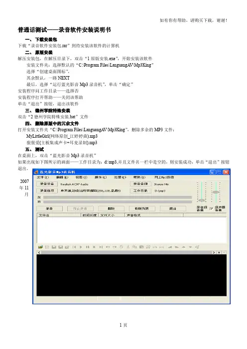
五、测试
在桌面上,双击“蓝光影音Mp3录音机”
如果出现如下图所示的画面——工作目录为:d:\mp3,并且文件名一栏中是空的,则安装成功,单击“退出”按钮退出。
教务处2007
年11
月
1页
如有你有帮助,请购买下载,谢谢!2页。
录音操作说明书
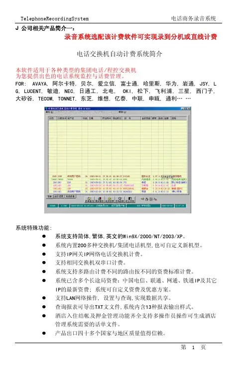
J公司相关产品简介一:录音系统选配该计费软件可实现录到分机或直线计费电话交换机自动计费系统简介本软件适用于各种类型的集团电话/程控交换机为您提供出色的电话系统监控与话费管理。
FOR:AVAYA,阿尔卡特,贝尔,爱立信,富士通,哈里斯,华为,岩通,JSY,L G,LUCENT,敏迪,NEC,日通工,北电,OKI,松下,飞利浦,三星,西门子,大矽谷,TECOM,TONNET,东芝,维想,亿泰,中联,申瓯,通利……系统特殊功能:�系统支持简体,繁体,英文的Win9X/2000/NT/2003/XP。
�系统内置200多种交换机/集团电话机型,也可自定义新机型。
�支持IP网关IP网络电话交换机计费。
�支持相同交换机双串口计费。
�系统支持多路由计费不同的路由按不同的资费标准计费。
�系统已含多个长途局资费:中国电信、联通、网通、铁通IP及其它IP的最新资费;系统可自定义资费及优惠方案。
�支持LAN网络操作,设置与查询,实现数据共享。
�查询报表可导出TXT文文件,系统内含13种报表输出样式。
�酒店入住结帐及押金管理功能齐全支持多操作员操作可生成酒店管理系统需要的话单文件。
�产品出口四十多个国家与地区质量值得信赖。
本手册所有提及之商标与名称皆属本公司所有。
在此不担保本手册无任何疏忽或错误,亦不排除会再更新发行。
手册若有任何内容修改,恕不另行通知。
产品板卡上的任何贴纸请勿自撕毁,否则会影响到产品保修期限的认定标准。
感谢您购买并使用电话商务录音系统在使用本产品前请仔细阅读下面的许可协议许可协议:同意本许可协议的所有条款是获得本产品许可的必要条件。
如果您不同意此协议的所有条款,请在三天内将产品退还软件代理商。
您对软件的使用表明您同意接受本协议中条款的约束。
1.授予您使用权限。
您可以为了备份的目的而复制光盘中的软件。
2.除已按上述第一条被授权外不可以复制、修改、逆向工程、分解或重组该产品的全部或部分不可向他人销售、租借、许可转让分发全部或部分本产品或本协议授予的权利。
教室音频系统安装及操作手册说明书

Classroom Audio System教室音频系统 Installation and Operating Manual安装及操作手册V 1.3重要的安全说明重要的安全说明1. 在安装和使用设备前请先仔细阅读本安全操作规程。
2. 请保存好您的安全操作指南便于以后作参考用。
3. 请遵守所有设备操作指南中的“警告”事项。
4. 须遵守各项操作指南中的规章原则。
5. 清洁设备:清洁设备之前,请先关掉电源,从插座中拔出设备插头,将各连接的系统单元拆卸出来,清洁时请用干燥的软布擦拭。
6. 未经生产厂家同意,不要使用任何不匹配的附件配置,这都有可能引起危险事故。
7. 勿将设备置于潮湿或靠近热源的地方,以免发生危险。
8. 设备不应遭受水滴或水溅,不应放置诸如花瓶一类装满液体的物品。
9. 电源插头作为断接装置,应便于操作。
10. 设备应可靠连接到带保护接地的电网电源输出插座上。
11. 勿将设备放置在不稳固的台面上;在运输过程中避免设备遭受强烈振动而引起损坏,建议在运输前选用合适的包装或使用原包装。
12. 请勿阻塞设备上的通风开口,并保持室内的空气通畅,便于设备的维护。
13. 供电电压:AC 100 V-240 V 50 Hz/ 60 Hz14. 设备连接所需要的延长电缆线请绕道穿行,勿有重物挤压,这样能有效维护系统的正常工作。
15. 每套系统中所连接的接收器不得超过规定数量,否则可能会导致整个系统中设备的异常工作,如有特殊要求请与距离您最近的深圳台电售后服务中心取得联系。
16. 确保设备不被任意拆开机壳,也不允许任何硬质导体或液态物质残留在机壳内。
17. 设备有需要维护时,不要自行拆卸,请及时与距离您最近的深圳台电售后服务中心取得联系。
18. 所有TAIDEN产品将提供一定期限(详见保修卡)免费保修,但人为损坏除外,例如:A. 设备因人为作用被摔坏;B. 因操作员操作不当而导致设备受损;C. 自行拆卸后而导致部分设备零件受损或丢失。
录音系统安装说明
一.计算机系统要求
硬件:
1) CPU:高于等于赛扬800 或与其相当者
2) 内存:大于等于128M
3) 声卡:Ac'97声卡或者主板支持Ac'97,没有USB Audio设备
软件:
WIN98,WIN Me,WIN2000,WIN Xp
二.驱动程序安装说明:
A. win98/me安装方法:
1、将USB录音盒接入计算机
2、根据提示安装USB Audio驱动,可能需要操作系统光盘。
3、运行\Driver\SetupFlt.exe点确定
4、重启计算机
5、安装应用程序,启动应用程序
B.win2000/xp安装方法:
1、将USB录音盒接入计算机
2、系统会自动安装USB Audio驱动。
3、运行\Driver\SetupFlt.exe点确定。
4、安装应用程序,启动应用程序
三.声音与多媒体属性设置:
1、安装完成驱动并重新启动机器后,在控制面板中打开“音频和多媒体”,选择“音频”页,
2、将声音播放首选设备设置为原来的声卡。
3、录音首选设备设置为“USB Audio Device”。
四.软件系统的安装方法
1、将整个目录拷贝到你的目标目录下。
2、将所有拷贝过去的文件的“只读”属性去掉。
(选定所有文件,按鼠标右键,选中菜单中的“属性”,里面可以修改文件属性)
3、直接运行目录下的TMN.exe就可以打开录音系统软件。
五.注意:
1、每台计算机仅仅支持一台MRU5002型号的USB录音盒
2、Driver目录下是录音设备驱动程序。
电话录音系统安装说明
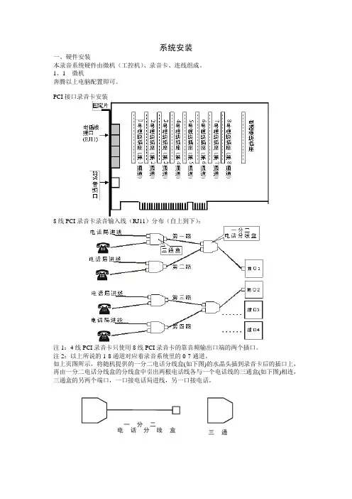
系统安装一、硬件安装本录音系统硬件由微机(工控机)、录音卡、连线组成。
1、1 微机奔腾以上电脑配置即可。
PCI接口录音卡安装8线PCI录音卡录音输入线(RJ11)分布(自上到下):注1:4线PCI录音卡只使用8线PCI录音卡的靠音频输出口端的两个插口。
注2:以上所说的1-8通道对应着录音系统里的0-7通道。
如上页图所示,将随机提供的一分二电话分线盒(如下图)的水晶头插到录音卡后的插口上,再由一分二电话分线盒的分线盒中引出两根电话线各与一个电话线的三通盒(如下图)相连,三通盒的另两个端口,一口接电话局进线,另一口接电话。
一分二电话分线盒三通盒注意:以上全部设置必须在微机电源关闭的情况下进行。
注意:由于电话录音系统一般在无人操作的情况下长时间运行,因此必须关闭CMOS和WINDOWS操作系统中的电源管理中有关CPU、硬盘等省电的选项,使微机始终处于全速运行状态,否则可能导致性能下降或出现意外错误。
二、软件安装PCI总线的显著优势是可以使录音卡成为即插即用(PNP)设备,安装PCI录音卡就如安装PCI的声卡、网卡一样方便。
用户可以省去一大堆繁琐的I/O地址和IRQ设置,并且不用担心出现资源冲突而导致安装失败。
2、1 板卡驱动安装1、关掉待安装微机所有电源,包括所有外设的电源,按需要安装好相应的模块,板卡直接安装在PC机的PCI插槽上,连接好线路即可。
2、开机后从“我的电脑”→“属性”→“硬件””→“设备管理器”中找到新硬件,右击新硬件选择“属性”,再选安装驱动程序。
3、在对话框中点击“下一步”按钮,出现带有选择按钮的窗口,选择第二项:“从列表或指定位置安装”。
4、点击“下一步”按钮,在窗口中点击“浏览”按钮,从窗口列表中找到驱动目录中的INF 文件,点击“确定”按钮。
5、出现“添加新硬件向导”提示框,并列出型号。
在型号列表框中选择所安装板卡的型号,然后点击“下一步”。
7、接下来的对话框中,点击“下一步”。
Episode ES-350 音频系统安装手册说明书

INSTALLATION MANUALES-350-OWLCR-M ES-350-OMLCR-LES-350-SNDBAR-30-BLK ES-350-SNDBAR-40-BLK ES-350-SNDBAR-50-BLK ES-350-SNDBAR-60-BLK ES-550-SNDBAR-40-BLK ES-550-SNDBAR-50-BLK ES-550-SNDBAR-60-BLK ES-550T-SNDBR-40-BLK ES-550T-SNDBR-50-BLK ES-550T-SNDBR-60-BLKpage | 2 Support 866.838.5052page | 3© 2018 Episode®A. Read these instructions.B. Keep these instructions.C. Heed all warnings.D. Follow all instructions.E. Do not use this apparatus near water.F. Clean only with dry cloth.G. Do not block any ventilation openings. Install in accordance with the manufacturer’s instructions.H. Do not install near any heat sources such as radiators, heat registers, stoves, or other apparatus (including amplifiers) that produce heat.I.Do not defeat the safety purpose of the polarized or grounding type plug. A polarized plug has two blades with one wider than the other. A grounding type plug has two blades and a third grounding prong. The wide bladed or the third prong are provided for your safety. If the provided plug does not fit into your outlet, consult an electrician for replacement of the obsolete outlet.J. Protect the power cord from being walked on or pinched particularly at plugs, convenience receptacles, and the point where they exit from the apparatus.K. Only use attachments/accessories specified by the manufacturer.L. Use only with the cart, stand, tripod, bracket, or table specified by the manufacturer, or sold with the apparatus. When a cart is used, use caution when moving the cart/apparatus combination to avoid injury from tip-over.M. Unplug this apparatus during lightning storms or when unused for long periods of time.N.Refer all servicing to qualified service personnel. Servicing is required when the apparatus has been damaged in any way, such as power-supply cord or plug is damaged, liquid has been spilled or objects have fallen into the apparatus, the apparatus has been exposed to rain or moisture, does not operate normally, or has been dropped.O. The equipment shall be used at maximum 45 degree C ambient temperature.P. To reduce the risk of electrical shock, do not open the equipment. For safety reasons it is only allow to the opened by qualified service personnel.Q. WARNING:To reduce the risk of fire or electric shock, do not expose this apparatus to rain or moisture. Additionally, the apparatus shall not be exposed to dripping or splashing and no objects filled with liquids shall be placed on the apparatus.R. The mains plug is used as the disconnect device and shall remain readily operable.S. The product shall be used on open bench.T. No naked flame sources, such as lighted candles, should be placed on the apparatus.U.The apparatus should be connected to a mains socket outlet with a protective earthing connection.page | 4OVERVIEWWelcome to Episode® Speakers. We appreciate your purchase and are committed to providing the highest-quality products possible.The Episode® Soundbar models are a superb choice for almost every type of home theater or home audio installation.They have been designed with advanced technological components that allow for high performance and a lifetime of enjoyment.IMPORTANT INSTRUCTIONS AND CONSIDERATIONSRead and understand all instructions.Before beginning installation, carefully plan location accounting for potential electrical, plumbing or other obstacles.RECOMMENDED AMPLIFIER POWERTo get the best performance from the Soundbar, an amplifier or receiver with the following power rating is recommended:ES-350-OWLCR-M – between 20 and 100 Watts RMS per channelES-350-OMLCR-L – between 20 and 100 Watts RMS per channelES-350-SNDBAR-30-BLK – between 20 and 100 Watts RMS per channelES-350-SNDBAR-40-BLK – between 20 and 100 Watts RMS per channelES-350-SNDBAR-50-BLK – between 20 and 100 Watts RMS per channelES-350-SNDBAR-60-BLK – between 20 and 100 Watts RMS per channelES-550-SNDBAR-40-BLK – between 20 and 100 Watts RMS per channelES-550-SNDBAR-50-BLK – between 20 and 100 Watts RMS per channelES-550-SNDBAR-60-BLK – between 20 and 100 Watts RMS per channelES-550T-SNDBR-40-BLK – between 20 and 100 Watts RMS per channelES-550T-SNDBR-50-BLK – between 20 and 100 Watts RMS per channelES-550T-SNDBR-60-BLK – between 20 and 100 Watts RMS per channelSPEAKER WIRETo connect the Soundbar to an AV Receiver or Amplifier, high-quality 14 to 16 gauge stranded speaker wire is recommended. The wire may be connected directly to the speaker’s removable screw-down terminals. Remember that you will need 3 runs of speaker wire to the Soundbar location as it contains the left, center, and right speaker.A special wire management channel has been included in the rear of the speaker so that a wall mounted speakercan sit flush on the wall.FEATURES• Replaces Left, Center, and Right channels in one convenient speaker• Extremely Low-Profile, Extruded Aluminum Cabinet• Knockout for Hidden IR Receiver• Flexible Mounting Options• Cabinet Top or Shelf Placement with included kickstands• On-Wall with included mounting plate• Flat-Screen with optional accessory that attaches to TV mountWHAT’S INCLUDED• (1) ES-350-SNDBAR-XX, ES-550-SNDBAR-XX, or ES-550T-SNDBR-50• (2) Kickstands for Cabinet placement• (2) Shoulder bolts for Kickstand and Wall Plates• (2) Large Flat Washers for Kickstands• (2) Rubber Feet• (1) Wall Plate Bracket with adjustable knobs• (4) Wood Screws for Wall Plate• (4) Small Flat Washers for Wall Plate• (1) IR Receiver Spacer Support 866.838.5052page | 5© 2018 Episode®INSTALLATION SPEAKER PLACEMENTThe ES passive series of soundbars are designed to be the Left, Center, and Right speakers of a home theater surround system. For most applications, placement should be below a flat screen TV on a cabinet top or shelf. Other options for placement include On-Wall using the included bracket, or attached to a Flat Panel mount using the optional Strong mount bracket.INSTALLING ON OR IN A CABINETConsiderations for PlacementWhen placing the Soundbar on a cabinet shelf, the front edge of the speaker should be flush with the front of the shelf. Placing the speaker further back on the shelf will degrade the sound quality of the speaker. Attaching the KickstandThe kickstand for the Soundbar allows for the angle of the Soundbar to be adjusted to maintain proper audio performance. When placing the Soundbar, adjust the kickstand height to angle the Soundbar towards the listener’s ears. See Adjusting the Kickstand for more information.1. Place the included Kickstands on the rear of Soundbaras shown. 2. U sing a shoulder bolt and washer for each Kickstand, tighten to secure the Kickstand to the Soundbar.Attaching the FeetTo ensure that the Soundbar will not slip when using the kickstands, (2) rubber feet have been included. The feet must be installed when using the kickstand. Place the feet 3” from the left and right outer edge, and ¼” from the front edge of the Soundbar.Note: When using the kickstand in the inverted position, thefeet should be placed at the front edge of the speakerNon-Inverted Kickstand Inverted Kickstandpage | 6Adjusting the KickstandAfter installing the kickstand and placing the Soundbar, adjust the angle of the speakers towards the listener’s ears.If the speakers point away from the listener’s ears, slide the kickstand up or down to achieve the proper angle. Note that the kickstand can be inverted when the Soundbar is pointing down.Mounting on a Wall Support 866.838.5052page | 7© 2018 Episode®CONSIDERATIONS FOR WALL MOUNTINGTo maintain a high level listening experience, the Soundbar should be as close to the TV as possible. Placing To maintain a proper listening experience, the Soundbar should be as close to the TV as possible. Placing the Soundbar more than 3” from the screen will separate the audio from the video and provide a poor viewing and listening experience, keep this in mind when locating the Soundbar.Before Installing the Mount• Locate and install the TV mount.• With the TV on the mount• Mark the position of the bottom of the TV.• Mark the position of the TV’s Center Point.• Remove the TV from the mount Attaching the Wall BracketNote: For ease of installation of the bracket and the Soundbar, we recommend that the TV be removed from the mount. This allows for the Soundbar to be placed properly.INSTALLING THE MOUNT (ES -550, AND ES -350)1. Locate wall studs using a stud finder (not included).2. Place the Bracket on the wall with the flat side towards the wall. Ensure the center of the bracket is lined upwith the center point of the installed television.3. Position the center of the bracket 2 ¼ ” from the bottom of the TV. This will place the Soundbar flush with thebottom of the TV when installed.Tip:T o allow for extra clearance, position the center of the bracket, 2 5/16” from the bottom of the TV. This will provide an extra 1/16” clearance (recommended for Tilt Mounts) allowing for any tolerance differences that may occur.4. Level the bracket and attach it to the wall studs using the horizontal screw hole slots. All 4 screws should beused, making sure to keep the bracket flat to the wall and securely attached.5. Attach the Soundbar to the bracket by placing the bracket’smounting bolts into the keyhole slots on the rear of the soundbar and dropping the Soundbar into place.Note:O nce installed, if the soundbar needs upward adjustment, the soundbar will need to be unattached from the bracket.To Adjust:Remove the soundbar from the bracket, then adjust the thumbscrews on the bracket by hand or using a flathead screwdriver if necessary.Replace the soundbar when adjustment is complete.Repeat the process if further adjustment is necessary.page | 8INSTALLING THE MOUNT (ES-500T)1. Locate wall studs using a stud finder (not included).2. Place the Bracket on the wall with the flat side towards the wall and the notched center mark facing up. TheSoundbar Center mark should be located at the center point of the installed television.3. Position the Bracket Vertical Center (C) v groove 2 ¼ ” from the bottom of the TV. This will place theSoundbar flush with the bottom of the TV when installed.Tip: T o allow for some extra clearance, position the Bracket Vertical Center (C), 2 5/16” from the bottom of the TV. This will provide an extra 1/16” clearance (recommended for Tilt Mounts)allowing for the any tolerance differences that may occur.4. Level the bracket and attach it to the wall studs using the horizontal screwhole slots. All 4 screws should beused, making sure to keep the bracket flat to the wall and securely attached.5. Attach the Soundbar to the bracket by placing the bracket’s mounting boltsinto the keyhole slots on the rear of the soundbar and dropping the Soundbarinto place.ATTACHING THE WALL BRACKET (ES-350-OWLCR)A wall mounting template has been included; use this template for proper and accurate positioning of the OWLCR.1. Locate wall studs using a stud finder (not included).2. Position the provided template on the wall in the desired location of the speaker. If the location does not allowfor this, use a wall molly or anchor with the appropriate weight rating for the Soundbar.3.Level the template and mark the wall with the screw locations. Support 866.838.5052page | 9© 2018 Episode®4. Secure the brackets to the wall.5. If mounting the OWLCR in a horizontal orientation, place the provided rubber bumpers in line with the bracketsat the bottom of the speakers. These are not needed when mounting in an vertical orientation.6. Place the Speaker onto the wall brackets with the rear screws in the slots. Slide the speaker onto the bracket.Your install is now complete.Slide OWLCRInstalling on a Flat Panel MountThe ES passive series of soundbars can be mounted directly to a Flat Panel Mount with the Strong™ SM-SBAR2-BKT-UNIV (available separately). Using the Flat Panel mount bracket allows for the speaker to move with the TV when mounted to articulating arm mounts. This provides an optimum listening experience for these installations.Installing an IR ReceiverThe ES passive series of soundbars have the option of installing an optional IR Receiver directly into the speaker behind the grille cloth, eliminating the need to surface mount a stick-on receiver. Simply punch out the center of the pass-through and slide the IR Receiver through the exposed hole.Note: Due to the extremely low profile of the ES-500T soundbars, most IR tube receivers will protrude through the rear of the Soundbar. An opening in the wall may be needed for clearance.page | 10To maintain accurate I R reception, a spacer has beenincluded to allow for the front edge of the IR receiver to beflush with the back of the grille cloth. This will ensure that IRreception is at its maximum level.TIP:W ith some IR receivers, a layer of electrical tapearound the threads can create a more snug fit withinthe SoundbarConnecting and CalibratingProper Connections are important to the performance of any loudspeaker within an audio system.Performing the following steps will ensure proper connections for optimum speaker performance:1. At each loudspeaker connection, ensure that the outer jacket is separated by at least 2 inches.2. Strip the insulation on each conductor approximately ¼” and insert into the speaker terminals.A. Ensure that there are no stray strands of wire protruding from the connectors.B. Observe proper polarity (+ to + and – to – ) for each speaker and at the amplifier).3. T urn on the home theater receiver and calibrate all loudspeakers in the system according to the receiver(or surround processor) manufacturer’s instructions.Verifying PhaseWhen proper polarity is not maintained, the speakers play at the opposite ‘time’ from each other, or out of phase.The result is audio with lack of bass and vocals that sound thin or distant. If during or after calibrating your receiver you suspect the sound is not right and you cannot see any markings on the wire to verify polarity is correct, try this simple test:1. Sit in the normal listening position for the system.2. Play some music with your receiver set to Mono.3. Listen to the music and observe the audio.A. Does the bass sound full and even with the other audio?B. Do the vocals sound centered and even in volume?C. I f either of the answers are YES, follow steps 3 and 4 with the other loudspeakers in the system.4. Turn off your receiver and reverse the connections for one of the speakers.5. Repeat your test at the same volume level. When the sound has the loudest and best sounding bass, andvocals are centered and clear, your connections are correct and in-phase.GENERAL MAINTENANCEINSTALLING AND REMOVING THE GRILLE• The grill is held by pins. To remove the grill, pull gently around the edge away from the speaker, slowly working your way from one end of the speaker to the other .• To re-install, align the grill pins with the cups in the speaker and push into place.CLEANING• Use a dampened soft cloth or paper towel to clean the cabinet. The grill is best cleaned by brushing it off with a lint-free cloth. Support 866.838.5052page | 11 SPECIFICATIONS© 2018 Episode®page | 12 Support 866.838.5052page | 13© 2018 Episode®page | 14 Support 866.838.5052page | 15© 2018 Episode®TROUBLESHOOTINGEpisode amplifiers are designed to function trouble-free. Most problems that occur are due to simple issues. I f having trouble, check the list of simple fixes below. If the problem persists, contact Episode technical support at866-838-5052.CONTACTING TECHNICAL SUPPORTAs a thank you for purchasing Episode® Electronics products, direct technical support services are available via phone or e-mail. We encourage you to use this resource for any questions or concerns about our products. Visit our website for more support documentation.(866) 838-5052********************** WARRANTYLimited Lifetime WarrantyEpisode Soundbar Speakers have a Lifetime Limited Warranty. This warranty includes parts and labor repairs on all components found to be defective in material or workmanship under normal conditions of use. This warranty shall not apply to products which have been abused, modified or disassembled. Products to be repaired under this warranty must be returned to SnapAV or a designated service center with prior notification and an assigned return authorization number (RA).© 2018 Episode®Rev: 180104-0425。
丛文录音服务器安装操作手册说明书
丛文录音服务器安装操作手册2016年1月版权说明本手册版权归深圳市丛文安全电子有限公司所有。
保留一切版权。
除了版权法允许的使用方法之外,未经事先许可,任何人不得复制、改编或翻译。
保证说明本手册所含之内容如有改变,恕不另行通知。
深圳市丛文安全电子有限公司对由于本手册的错误而引起的损害不承担责任,对由于提供或使用本手册而随带发生的损害亦不承担责任。
商标说明丛文®是深圳市丛文安全电子有限公司的注册商标。
CONWIN®是深圳市丛文安全电子有限公司的注册商标。
简介目录第1章系统功能概述 (2)1.1简介 (2)1.2功能特点 (2)1.3产品型号 (2)1.4系统结构及流程图 (2)1.5录音服务器安装流程图 (3)第2章安装录音服务器 (4)2.1安装环境 (4)硬件环境 (4)软件环境 (4)2.2硬件板卡安装 (4)硬件安装 (4)录音服务器2线/4线板卡接线方法 (4)录音服务器8线板卡接线方法 (8)2.3软件安装 (10)2.4卸载 (15)第3章录音服务器应用 (16)3.1系统功能 (16)系统设置 (16)录音设置 (16)查看语音卡安装及录音情况 (19)系统登陆与注销 (20)登陆密码管理 (21)3.2查看信息资料 (21)录音记录管理 (21)站点信息 (22)查看系统错误信息 (23)第4章报警中心启用录音服务器设置 (24)4.1启用录音服务器 (24)4.2录音并关联警情 (24)自动拨打电话关联警情 (24)手动关联相关警情 (26)查看相关的报警 (27)导出录音文件 (27)播放录音文件 (27)第5章售后服务 (29)第6章加密锁安装及升级方法 (30)简介第1章 系统功能概述1.1 简介录音服务器应用于接警中心领域,通过联网报警中心软件拨打用户电话,减少手动拨打出现的出错几率并与用户确警的电话进行全程录音,同时录音文件会与当时发生的警情自动相互关联,以备日后在查看警情的同时播放录音文件,为报警中心与公安机关留下关键有力的证据。
原SOC1800电话录音系统用户手册
SOC1800电话录音系统使用指南资料版本:UG-1800-V1.02008年5月发行版权所有·不得翻印© 2008 申瓯通信本产品的所有部分,包括配件及软件等,其所有权都归申瓯通信设备有限公司(以下简称申瓯)所有,未经申瓯公司许可,不得任意地仿制、考贝或转译。
本使用手册中所谈论到的其它产品名称仅做识别之用,而这些名称可能是其它公司的注册商标。
产品(包括硬件及软件)更新后,使用指南都会随之更新,更新的详细指南请到申瓯公司网站下载或直接与申瓯公司联系。
申瓯通信设备有限公司目录一、安全性须知 (4)1.1 电气方面的安全性 (4)1.2 操作方面的安全性 (4)1.3申瓯通信的联络资讯 (4)二、产品介绍 (5)2.1 产品包装 (5)2.2 产品特写 (5)三、产品安装 (7)3.1 前面板视图 (7)3.2 后面板视图 (7)3.3 连接话机和录音盒 (7)3.3.1 带配线架的连线方法 (7)3.3.2 双接线孔话机的连接方法: (8)3.3.3 单接线孔话机的连接方法: (8)3.4 接通电源 (9)3.5 开始录音 (9)四、登录web网管管理录音 (10)4.1 系统IP地址设置 (10)4.2 管理员管理 (15)4.2.1 系统信息 (16)4.2.1.1 系统基本信息 (16)4.2.1.2 WEB IP地址设置 (16)4.2.1.3 设置MAC地址 (17)4.2.1.4 恢复出厂设置 (17)4.2.1.5 在线升级 (18)4.2.1.6 设置系统实时时钟 (18)4.2.1.7 权限管理 (19)4.2.1.8 管理员管理 (19)4.2.1.9 FTP管理 (20)4.2.2 录音管理 (20)4.2.2.1 录音通道列表 (21)4.2.2.2 按录音通道查询 (21)4.2.2.3 按月查询 (22)4.2.3 功能设置 (22)4.2.3.1 相关功能设置 (22)4.2.3.2 录音时间段设置 (23)4.2.4 号码分组 (23)4.2.4.1 分组信息 (23)4.2.4.2 分组设置 (24)4.2.4.3 号码过滤 (24)4.3 通道帐号管理 (25)2五、使用录音管理软件管理录音 (26)5.1 安装录音管理软件 (26)5.2 软件使用方法: (27)5.2.1 设置录音设备的IP地址 (27)5.2.2 设置录音文件备份路径和起止日期 (28)5.2.3 下载录音 (29)5.2.4 查看录音 (30)5.2.5 播放、另存录音 (31)5.2.6 全局查询——查询符合您条件的录音 (32)六、SOC1800座席弹屏软件的使用 (33)6.1 SOC1800座席弹屏软件的安装 (33)6.2 使用座席弹屏软件 (34)6.2.1 连接录音设备 (34)6.2.2 下载通话记录 (35)6.2.3 查询通话记录 (35)6.2.4 来电弹屏 (36)6.2.5 客户管理 (36)6.2.6 增加客户 (37)6.2.7 客户类型 (37)6.2.8 客户资料导入导出 (38)七、服务与有限责任保证 (39)7.1 维修服务 (39)7.2 有限责任保证 (39)3一、安全性须知1.1 电气方面的安全性·为避免可能的电击造成严重损害,在搬动本录音盒前,请先将电源线暂时从电源插槽中拔掉。
MDR电话录音系统操作手册
M D R电话录音系统操作手册This manuscript was revised by the office on December 10, 2020.二、基本操作2.1主窗口说明主界面一说明:1.两个图都是录音系统的主界面,他们之间可以自由切换。
主界面一为大图标显示,主界面二为列表方式显示,可以即时显示每个通道的状态。
2.主界面的最上方是菜单条,紧接着是快捷按钮。
菜单条与快捷按钮可以实现相同的功能,不过快捷按钮更方便些。
屏幕中间的大区域为每个通道的状态显示。
屏幕的右方与下方为用户与系统的状态显示。
3.当系统主界面启动后,录音系统即处于工作状态。
4.监听:本系统提供即时监听功能,用户用鼠标双击某一线路的图标,即可监听此线路,再次双击此线路则取消监听。
同一时刻只能监听一个通道。
5.通道状态图标说明:断线录音空闲监听录音摘机不可用留言空闲主界面二2.2模块功能主画面上方有录音系统的功能菜单,通过本菜单可以对录音系统进行全部操作。
包括:日常操作查询统计录音设置参数设置帮助1.日常操作1)登录:用户输入用户名与密码后,可以实现登录,不同的用户可以有不同的权限。
2)注销:用户完成操作后,可以注销此用户,这样其他用户要操作本系统时必须登录。
3)界面切换:切换主界面中各线路状态的显示方式,详细见主界面一与主界面二。
4)退出:关闭录音系统。
2.查询统计1)录音查询本功能是录音系统最常用的功能,在这里,用户可以完成录音文件的查听、备份、除、注释、打印等功能。
说明:查询:用户必须先查询出录音文件,然后才可以对文件进行放音,注释,备份、删除等操作。
1. 查询条件时间:可以设置查询的开始与结束时间,默认为当天。
电话号码:此号码为用户拨入或拨出的电话号码,*代表全部,5039*表示以5039开始的所有的电话号码。
*5039*表示包含5039的所有的电话号码。
备注:根据用户设置的备注信息进行查询。
电话分类:根据电话分类(可在电话本中设置分类)进行查询。
DMCC Recorder系统安装配置手册
Wilcom DMCC Recorder 系统安装使用手册1 1上海井星信息科技有限公司Wilcom DMCC Recorder 系统安装配置文档版本号:V2.00.06212010-07-03Wilcom DMCC Recorder 系统安装使用手册2 2目 录1. 概 述 (4)1.1读 者 ...................................................................................................................................... 4 1.2系统框架说明 ......................................................................................................................... 4 1.3系统介绍 ................................................................................................................................. 5 1.4系统特点 ................................................................................................................................. 6 2.系统网络拓扑图 .............................................................................................................................. 7 3. 环境准备 (7)3.1硬件环境 ................................................................................................................................. 7 3.2 软件环境 (8)4. 安装步骤 (9)4.1安装说明 ................................................................................................................................. 9 4.2 相关组件安装与配置 . (9)4.2.1安装JDK (9)4.2.2 安装.NET Framework3.5 (9)4.2.3 Avaya AES Client 安装与配置 (9)4.2.4 Avaya AES Client 测试 (10)4.2.5 安装ActiveMQ (11)4.2.6 ActiveMQ 服务设置 (12)4.2.7 ActiveMQ 测试 (12)4.3 DCMPS ERVER 安装与配置 (13)4.3.1 安装JDK (13)4.3.2 DCMPServer 安装与配置 (13)4.4 DCMPA GENT 安装与配置 (14)4.4.1 安装JDK (14)4.4.2 DCMPAgent 安装与配置 (14)4.5 R ECORDQUERY 安装与配置 (15)4.6 V OX B ACK U P 安装与配置 (15)5. 系统配置 (16)5.1 服务器配置 ........................................................................................................................... 16 5.1.1进入管理配置 ............................................................................................................... 16 5.1.2创建CTI 对象 ............................................................................................................... 16 5.1.3创建IPRS 对象 ............................................................................................................. 19 5.1.4 创建MPS 对象 . (21)Wilcom DMCC Recorder 系统安装使用手册3 36. 系统使用 (23)6.1创建CTI 实例 ....................................................................................................................... 23 6.2创建IPRS 实例 ..................................................................................................................... 24 6.3创建MPS 实例 ..................................................................................................................... 25 6.4CTI 配置 ................................................................................................................................ 26 6.5IPRS 配置 ............................................................................................................................. 28 6.6MPS 配置 .............................................................................................................................. 30 6.7 S ERVER 备份设置 (32)6.7.1 MPS 主备设置 (32)6.7.2 CTI 主备设置 (33)6.7.3IPRS 主备设置 .................................................................................................................. 34 7. 技术支持 . (34)Wilcom DMCC Recorder 系统安装使用手册441. 概 述随着市场竞争的日益激烈,客户服务已经成为了企业竞争的极为有效的战略之一,而实现这一战略的重要环节是呼叫中心。
- 1、下载文档前请自行甄别文档内容的完整性,平台不提供额外的编辑、内容补充、找答案等附加服务。
- 2、"仅部分预览"的文档,不可在线预览部分如存在完整性等问题,可反馈申请退款(可完整预览的文档不适用该条件!)。
- 3、如文档侵犯您的权益,请联系客服反馈,我们会尽快为您处理(人工客服工作时间:9:00-18:30)。
录音系统安装手册
一、服务器安装说明
安装步骤:
1)、东进语音卡的安装:
a、安装东进语音开发包DJDBDK(3.4.0/3.6.3),默认安装,安装完成之后重启电脑,
如下图:
驱动安装:选择“否,暂时不”,点击下一步
选择“从列表或指定的位置安装(高级)”点击下一步
选择光驱下G:\DJDBDK\Win2000,点击下一步
在弹出的窗口中选择“仍然继续”
然后直到安装完毕,重启计算机。
安装完成之后,在任务管理器中,语音卡的状态显
示为
b、模拟卡检测及加载(以下图片仅做参考,显示的卡为3个模块6个通道):
修改配置文件,修改“开始”“所有程序”“DJDBDK”“DJD161A”“TC08A-V.INI”中EnhanceConf = 2,WaveFormat = 1;
选择“开始”“所有程序”“DJDBDK”“DJD161A”“AutoCheck”出现
如下界面:
依次点击“PCI Board Start”和“Save an Exit”按钮加载语音资源,检测正确结果如下:
然后选择“开始”“所有程序”“DJDBDK”“DJD161A”“Phone Bank Demo”,出现如下界面:
通道数由本次检测到的语音卡为准。
C、8线模拟卡的线路连接,参考C:\DJDBDK\Help\DJD161a目录下的D161A-D081A.chm 帮助文件。
D、数字卡的检测与加载:
选择“开始”“所有程序”“DJDBDK”“DJSs1”“SS1 AutoCheck”,依次点击“PCI Board Start”和“Save an Exit”检测语音卡,然后选择“开始”“所有程序”“DJDBDK”“DJSs1”“SS1 Download”加载数字语音卡。
修改“开始”“所有程序”“DJDBDK”“DJSs1”“Tce1-32.ini”中[ModeArray]目录下的PcmMode数组的值都为1,如图:
2)、将录音服务器整个文件拷贝到D盘根目录下;
3)、使用软件注册程序获得语音卡编号,从语音卡注册码文件中查到对应的注册码,填入注册软件中,点击注册,注册成功会有相应的提示;
4)、将OraDB.sql数据库脚本文件导入oracle数据库中;
5)、在操作系统中建立一个用户名为hbtx的管理员用户,密码设置为pass;
6)、在需要存放录音文件的盘符下建立一个名为Server的文件夹,并将其设置为系统共享,即共享名为Server$;
7)、在Setup文件夹目录下找到配置文件server.ini,修改数据库信息、业务服务器信息、业务服务器端口号、录音台号、录音卡的类型、录音路径等信息,在服务器上建立一个数据库服务,数据库SID设为数据库网络服务名,说明如下(有红字说明的部分需要根据实际情况进行修改,其它项无需修改):
[系统设置]
管理员 = 00000000
管理员密码 =222222 //系统退出密码
数据库IP =192.168.0.2 //数据库IP
数据库SID =zitorcl //数据库SID
数据库用户 =SZREC122 //数据库用户
数据库密码 =SZREC122 //数据库密码
数据库端口号 =1521 //数据库端口号
APPSERVER =192.168.0.100 //设为录音服务器需要连接的业务服务器IP地址APPPORT =1003 //设为录音服务器需要连接的业务服务器端口号
录音路径 =d:\server\ //录音文件存放路径,即第6)步中设置的serve文件夹路径组号 = 1
线号 = 1
录音台IP = 192.168.0.9 //录音台IP地址
录音台号 =1 //录音服务器的编号,综合话务平台的编号为0,录音平台编号从1开始服务端口号 =5110
窗体标题 = ZXRD1000 //窗体标题
Logo = 录音服务器//程序名称
收主叫方式 = DTMF //两种方式:DTMF和FSK
[中继设置]
;USER模拟卡,SS1中继卡(大写)
中继卡类型 = USER //模拟卡设为USER(大写),数字卡设为SS1 (大写)
部线路总数 = 4
外线坐席 = 2
流水编号 =02
录音编号 =01
初始语音文件表=C:\DJDBDK\Prompt.ini
放音线路开始=31
放音线路结束=32
外线呼出开始=32
外线呼出结束=33
线呼出开始=1
线呼出结束=2
;中继卡类型=SS1
呼出中继开始 = 1
呼出中继结束 = 30
;中继卡类型=SS1 时有效
[用户设置]
自动等待超时处理=1
自动最大等待时间=20
人工最大排队时间=60
自动最大服务时间=3000
人工最大服务时间=1800
最大振铃时间=30
最大呼出振铃时间=60
留言时间=20
转接控制=0
报警语音提示 = 1
;2时 122接119 转,1时122、119直接转,0时本地接。
锁订控制 = 1
;0不处理,1播放教育语音,2挂断。
火警优先 = 0
;0时间最长优先。
1火警时间最长优先
呼出控制 = 0
0 数字中继呼出外线 1 模拟中继呼出外线 2都可数字中继优先3都可模拟中继优先8)、模拟卡并线录音,配置文件中,中继卡类型设置为USER,数字卡中继录音,中继卡类型设置为SS1。
9)、模拟卡并线录音需要修改程序根目录下Access数据库中的seat_info表,如下图:
Phone_No为,它对应的通道号、座席号分别为Line_ID 、Seat_No,RecType设为1,Line_ID的编号从0开始;(主意:不同的线路不能设置相同的)
10)、建立Ftp服务器,安装ServU6404,默认安装,安装完成之后设置如下:
默认点击“Next”按钮进入如下界面,填入本机的IP地址,
点击“NEXT”按钮进入如下界面,填入自定义域名,
点击“NEXT”按钮进入如下界面,选择“Yes”
点击“NEXT”按钮进入如下界面,选择“No”
点击“NEXT”按钮进入如下界面,选择“Yes”
点击“NEXT”按钮进入如下界面,填入“TelRec”
点击“NEXT”按钮进入如下界面,填入“huabotongxun”
点击“NEXT”按钮进入如下界面,选择录音文件夹路径如“D:\server”
点击“NEXT”按钮进入如下界面,选择“Yes”
点击“NEXT”按钮进入如下界面,
点击“NEXT”按钮进入如下界面,
点击“Finish”按钮安装完成。
然后点击Sever-U主界面中的license选项,在其中输入注册码,如下图所示
然后点击“Apply”按钮完成设置,在任务栏中会出现一个绿色的U型图标。
二、客户端安装说明
安装步骤:
1)、将录音软件客户端拷贝到任意系统盘下;
2)、修改配置文件LOGIN.INI中的数据库信息,录音文件目录等配置参数,说明如下:在配置文件RecServerInfo.ini,在其中填入所有服务器的名称,(用于访问多台录音服务器的录音,如果只有一台服务器,则不需要填写)如图
然后在配置文件Login.ini文件中,增加这么些服务器的数据库信息,包括数据库IP地址、数据库SID、用户名和密码,如图所示:
[system]
;数据库IP,数据库SID,用户名,密码
DATASOURCEIP = 192.168.0.2 //数据库IP
DATASERVER = ora9i //数据库SID
DATAUSR = SZREC122 //数据库用户名
DATAPSW = SZREC122 //数据库密码
RECLEN = 3 //录音文件时长
;录音文件所在目录
RECSYSDIR = \\192.168.0.211\server$\//录音文件所在目录
RECUSERNAME = hbtx
RECUSERSW = pass
;窗体信息设置
窗体标题 = 华伯科技
LOGO = 录音查询系统
备注 = 华伯科技
[南山]
;数据库IP,SID,用户名,密码
DATASOURCEIP = 192.168.0.9
DATASERVER = ora9i
DATAUSR = wireless
DATAPSW = pass
[福田]
;数据IP,SID,用户名,密码
DATASOURCEIP = 192.168.0.11
DATASERVER = ora9i
DATAUSR = REC122
DATAPSW = REC122
[罗湖]
;数据IP,SID,用户名,密码
DATASOURCEIP = 192.168.0.12
DATASERVER = ora9i
DATAUSR = 122
DATAPSW = 122
其中[System]下的信息为本地录音服务器数据库信息。
说明:以上图例仅供参考,具体设置请以现场情况为准!。