阀门样本
KOSO无锡工装阀门样本(指南)

旋转阀样本(中/英文对照)产品型号210E 偏芯角行程调节阀(对夹式) SS-CE-210E-B.pdf210C 同芯角行程调节阀(对夹式) SS-CE-210C-C.pdf220E 偏芯角行程调节阀(法兰式) SS-CE-220E-A.pdf310K 直通球阀SS-CE-310K.pdf--------------------------------------------------------------------------------球形阀样本(中/英文对照)产品型号501T 顶部导向型单座调节阀(流体压力不平衡型) SS-CE-501T-B.pdf501T 顶部导向型单座调节阀(全蒸汽夹套型) SS-CE-501TJ-B.pdf501B 顶部导向型单座调节阀(流体压力平衡型) SS-CE-501B-B.pdf501G 套筒导向型单座调节阀SS-CE-501G-B.pdf530G 套筒导向型双座调节阀SS-CE-530G-B.pdf510D 多级降压式套筒导向型调节阀SS-CE-510D-A.pdf550G 多孔式套筒导向型调节阀SS-CE-550G-C.pdf522F/532F 三通分流型/合流型调节阀SS-CE-522F·532F-A.pdf 501T 高压顶部导向型单座调节阀SS-CE-501Th-A.pdf501G 高压套筒导向型单座调节阀SS-CE-501Gh-B.pdf 510D 高压多级降压式套筒导向型调节阀SS-CE-510Dh-A.pdf 500A/510A/520A 高压顶部导向型单座角阀SS-CE-500A-B.pdf511G 高压套筒导向型角阀SS-CE-511Gh-A.pdf 520D 高压多级降压式套筒导向型角阀SS-CE-520D-A.pdfVSD 低温角阀SS-CE-VSD-A.pdf800P 自力式压力调节阀(外部取压型) SS-CE-800P-A.pdf820P 自力式压力调节阀(内部取压型) SS-CE-820P-A.pdf400H 平行闸阀SS-CE-400H-A.pdf--------------------------------------------------------------------------------蝶阀样本(中/英文对照)产品型号710E 高性能蝶阀(对夹式) SS-CE-710E-C.pdf710C 高性能蝶阀(对夹式) SS-CE-710C-A.pdf720E 高性能蝶阀(法兰式) SS-CE-720E-A.pdf600S 低负载型蝶阀SS-CE-600S-A.pdf600B 中等负载蝶阀SS-CE-600B-A.pdf600M 衬胶蝶阀SS-CE-600M-B.pdf--------------------------------------------------------------------------------执行机构样本(中/英文对照)产品型号5200LA 气动薄膜式执行机构(直行程) SS-CE-5200LA-A.pdf6300LA 气动活塞式执行机构(直行程) SS-JE-6300LA-A.pdf5200RA 气动薄膜式执行机构(角行程) SS-CE-5200RA-B.pdf6300RB 气动活塞式执行机构(角行程) SS-CE-6300RB-B.pdf6400RB 气动活塞式执行机构(角行程) SS-CE-6400RB-A.pdf6500RB 气动活塞式执行机构(角行程) SS-CE-6500RA-A.pdf7300RA.RB 气动活塞式执行机构(角行程) SS-CE-7300RA·RB-A.pdf 3800LA/RA 电液式智能型执行机构(直/角行程) 3800.pdf (中文)--------------------------------------------------------------------------------附件样本(中/英文对照)产品型号EP800 电-气定位器(直/角行程) SS-CE-EP800-B.pdfEPL800 电-气定位器(直/角行程) SS-CE-EPL800-A.pdf--------------------------------------------------------------------------------进口产品样本(日/英文对照)产品型号501T 顶部导向型单座调节阀(流体压力不平衡型) SS-JE-501T-A.pdf520T 顶部导向型小流量调节阀SS-JE-520T-A.pdf510D 高压多级降压式套筒导向型调节阀SS-JE-510DH-A.pdf 530D 高压多级降压式套筒导向型调节阀(4500#) SS-JE-530DH-A.pdf710C 高性能蝶阀SS-E-710C-E.pdf (英文) 3400LA/RA 电动执行机构(直/角行程) SS-JE-3400-A.pdf3600LA/RA 电子式执行机构(直/角行程) SS-JE-3600-A.pdf3620RA 电子式执行机构(角行程) 3620.pdf3900RA 电动式执行机构(角行程ON-OFF 型) 3900.pdf6400RB 气动活塞式执行机构(角行程) SS-JE-6400RB-A.pdf。
纽威阀门样本 Neway Valves

Cat.no.:E-BFVCat.no.:E-PVCat.no.:E-CSV Cat.no.:E-PS Cat.no.:E-FSVCat.no.:E-PLVNo.999 Xiangjiang Road, Suzhou New District,P .R. China Post Code:215129Tel: 86-512-666-51365Fax: 86-512-666-51360E-Mail: neway@ C a t .n o .:E -P V -2005-U S12315 Parc Crest Drive Suite 190Stafford, T exas 77477Phone: 281-933-5775Fax: 281-933-5779JAG Flocomponents USA, Ltd.U.S. Sole Distributor:Manufacturer:Cat.no.:E-MVN the safety and protection ofe w a y r e c o g n i z e s t h eimportance of valve quality for personnel health and property. It is our quality commitment to focus our resources to provide our customers with first class products at a competitive price, that are designed, manufactured, inspected and tested in accordance with our customers, specifications and that comply with all international standards.With respect to the facts that the current industrial standards do not always take into consideration the likelihood and consequences of possible deterioration in service, related to specific service fluids or the external environment in which they operate. Our customers are requested to keep an open line of communication withNEWAY technical research center utilizes the most advanced computertechnology to improve the existing products and develop the new lines, this includes a highly educated and trained engineering team and a comprehensive internal computer network which links the entire operations of design, manufacturing and administration.NEWAY design philosophy is to develop a safety and cost-efficient valve, we introduced the latest AUTO CAD and I-DEAS software for all our new product design research which include the advanced finite element analysis to virtually verify the new design prior to production, this has resulted in dramatically reducing the new product design time and ensure a safety and cost efficient final product.NEWAY technical personnel are always ready to offer on line or on site technical training and support for all of its distributors, agents and end users.Fire safe is standard design of all NEWAY ball valve.Technical InnovationAPI 6D API 607API 6FA BS 5351BS 6755ANSI B16.34ANSI B16.10ANSI B16.5MSS SP-25MSS SP-55 NACE Std MR0175SHELL MESCAPI 598 Fire Safe Test CertificateTest FacilityTest ChartCNC LatheThe latest computer technology are also widely applied in NEWAY for valve manufacturing, this include a large number of numeric control machines (Machining center, CNC horizontal and vertical lathe, CNC drilling machine) and ERP management system which significantly improve our machining quality and process control. NEWAY also employes a number of conventional lathe with capacity up to machine 48ball valve.NEWAY manufacturing philosophy is to ensure stable quality and just in time delivery.4.2M Lathe CNC Lathe Automatic welding MachineMachining CenterCNC DrillingNEWAY developed an extensive and advanced inspection and test facilities to control the quality from rough castings or forgings to final products. These facilities enable us to do Radio graphic test, Ultra-sonic test, Dye-penetrate test, Magnetic test, Positive Material Identifier (PMI), Impact test, T ensile test, Hardness test, Fire safe test, Cryogenic test, Vacuum test, Low fugitive emission test and Hydro-static test.NEWAY Quality Assurance is dedicated to the pursuit of a zero defect valve, and this has resulted in the company having more quality qualifications and end user approval than most of our competitors. NEWAY is certified by ISO 9001 (certificate under DNV) and API 6D (registered no. 6D-0285) and our off-shore platform valves are type approved by ABS. Moreover, NEWAY is the first valve manufacturer in China to be certified to CE/PED (category IV, mode B+D, certificate under B.V.), All of NEWAY soft seated ball valves are fire safe tested and certified by Lloyd s Register.Part number identificationControlled Stem & Stuffing Box FinishFor the elimination of air pollution, it is essential to control the fugitive emissions leakage of various chemicals from valves in your chemical plant. NEWAY low emissions ball valves installed with our emissions defense packing have been designed and tested to m e e t t h e 100 P P M m a x i m u m e m i s s i o n l e v e l (acceptance test per Shell SPE 77/312). This is NEWAYstandard specification for all series BA, B and BB flanged floating ball valve.The stem surface finish is controlled between Weather proofbelleville-spring washerLow Emission packingFire Safe Seat SealingAdditionally, the fire safe metal seat can prevent the line pressure erosion on soft seat and minimize soft seat creep deformation. All NEWAY floating valves fire safe is designed and test certified in accordance with API 607.When static are generated and concentrated on the ball, the spring-loaded pins installed on ball, stem are provided to ensure electrical continuity throughout the valve.Anti-Static DeviceStem lower end is integral T shaped designed to be blow-out proof. It is internally inserted and functions as the backseat for assured stem sealing at all pressuresBlow-out Proof StemBefore FireBodyStemPacking ClosureBall StemPackingBallSeatBodyPackingStemAnti-Static DeviceClosureBodyBallGasketClosureWhen non-metal sealing material are decomposed or deteriorated by a plant fire, the upstream line pressure pull the ball into contact with the metal seat lip beneath the soft seat to shut off the line fluid to minimize the internal leakage.Design Feature:Live Loaded Gland FlangeLow Emission PackingLive loading is designed to provide gland load retention, compensating for expected in-service consolidation of the packing. A set of Belleville-Spring Washers are used on each gland stud to help exert a continuous compressive force on the gland follower flange and therefore reduce fugitive emissions from the stem packing. NEWAY standard Belleville-Spring Washers are protected by a weatherproof cap to keep them free from environmental contamination, resulting in a longstable life.The packing set is a combination of parallel and vertical layer sealing elements, which are made of expanding graphite in die-formed rings and have features of heat resistance, less stress relaxation and low creep. With this special structure, it allows for a low-friction on rotary & rising stem valves, therefore providing the stabilized seal performance for long cycle life.For medium and low temperature service, the standard V shape PTFE packing rings are installed for lowemission control.Floating Ball Valve Design FeatureLow Emission Control2963161861171514128137541110Series FE1 Ball ValveRegular port, uni-body, end entry designBlow-out Proof StemInternally inserted and functions as the backseat for assured stem sealing at all pressuresMetal-to-Metal Sealing When non-meatl sealing is deteriorated by fire,ball floats to shut off the line fruidEmission-free Graphite primary gasketIndex noPart123456789Index no PartBody Closure BallGland Flange Lever Seat Ring Stem Gland Gasket101112131415161718Grounding Washer Packing Set Stop Plate Thrust Washer Retainer Washer Bolt Rotaining SpringSeries FE1 Ball ValveSeries FE1 Ball ValveRegular port,uni-body,cast steel,end entry designClass 150LBWeight KgW mmH mmL mmD mmd mmSizeinDimensionsWW DLdHWDLddHGear Operator1 / 22 3101 / 23 / 411-1/222-1/23468101 / 23 / 49.512.71930385164761141441879.512.712.71925.43851647610215220325412.719108117127165178191203229267292330140152545964901021121211662082463035459120140140160265265265300400 300 * 400 *120140 1.72.72.985.008.7112.416.6624.38541011502.83.61638111071817962416135151412Series FB2 Ball Valveavailable in size from to 12 full port or witnessed and certified by Lloyd s Register.Double "D" Stem HeadProvides mounting of the lever handle alwaysin parallel to the flow passage Blow-out Proof Stem Internally inserted and functions as the backseat for assured stem sealing at all pressuresEmission-free Graphite primary gasket Metal-to-Metal SealingWhen non-meatl sealing isdeteriorated by fire,ball floats to shut off the line fruid easily for installation of gear, motor or pneumatic actuator 123456789Body Closure Ball Yoke Gland Flange Seat Ring Stem Gland Gasket 101112131415161718Grounding Washer Packing Set Thrust Washer Stud Nut Bolt Bolt Spring Steel BallSeries FB2 material specifications Series FB2 Ball Valve Two-piece,split body,cast steel,side entry design Full Port Size in D mm L mm H mm W mm Weight Kg Reduced Port Size in D mm L mm H mm W mm Weight Kg d mm 150L B Gear Operator Dimensions W H D L Full Port WH d D L Reduced Port W 123456789101112131415161718No. Part Standard Stainless Steel Sour Service Low TemperatureServiceASTM A352-LCB ASTM A352-LCB ASTM A182-F316ASTM A216-WCB ASTM A216-WCB PTFE ASTM A182-F316ASTM A182-F316316SS + Graphite Graphite PTFE PTFE ASTM A320-L7M ASTM A194-7M ASTM A320-L7M ASTM A320-L7M S.S.S.S.ASTM A216-WCB ASTM A216-WCB ASTM A105/ENP ASTM A216-WCB ASTM A216-WCB PTFE ASTM A182-F6a ASTM A276-420316SS + Graphite Graphite PTFE PTFE ASTM A193-B7M ASTM A194-2HM ASTM A193-B7M ASTM A193-B7M S.S.S.S.ASTM A351-CF8M ASTM A351-CF8M ASTM A182-F316ASTM A351-CF8M ASTM A351-CF8M PTFE ASTM A182-F316ASTM A182-F316316SS + Graphite Graphite PTFE PTFE ASTM A193-B8ASTM A194-8ASTM A193-B8ASTM A193-B8S.S.S.S.ASTM A216-WCB ASTM A216-WCB ASTM A105/ENP ASTM A216-WCB ASTM A216-WCB PTFE ASTM A182-F6a ASTM A276-420316SS + Graphite Graphite PTFE PTFE ASTM A193-B7ASTM A194-2H ASTM A193-B7ASTM A193-B7S.S.S.S.Body Closure Ball Yoke Gland Flange Seat Ring Stem Gland Gasket Grounding Washer Packing Set Thrust Washer Stud Nut Bolt Bolt Spring Steel Ball 1 / 23 / 411-1/222-1/23456810121 / 2131925385164761021251522032543051310811712716517819120322935639445753361014059637697107142152178252272342345479591301301602302304004007001100 300 * 300 * 400 * 600 *1303/4*1/2*3/43/4*1/2*3/41*3/4*11-1/2*1-1/22*1-1/2*22-1/2*2*2-1/23*2-1/2*34*3*46*4*68*6*810*8*1012*10*121.782.003.517.2311.0515.022.036.058.0110.0195.0309.0346.02.29131925385164761021522032541319253851647610215220325430519117127165178190203229394457530610152828510011512015316219129034044282130130160230230400400460 300 * 300 * 400 *130 3.04.57.09.515.016.029.548.0123.0212.0230.03.5Series FB2 Ball Valve122019178111354197161021181631415296Blow-out Proof Stem Internally insertedand functions as the backseat for assured stem sealing at all pressuresSeries FB2 Ball Valve Two-piece, split body, forged steel, side entry design This series ball valves are featured with two-piece bolted with flanged end body and floating ball. Body and closure are fully forged steel made which eliminate the inevitable casting defects and is ideal for high pressure service. FB2 series ball valves are available in size from 1 /2 to 4 and offers ANSI class rating 600 to 2500, all meet the fire safe requirements of BS 6755 and API 607. Blowout-proof stem, anti-static device and locking device are standard design, low emission packing with live loaded gland flange design can be available upon request. Manual handle operation is basic standard, but fully machined mounting pad can also easily install with gear, motor or pneumatic operator.ANSI Class 150 to 300 and Three-piece design can be supplied upon request.Double "D" Stem HeadProvides mounting of the lever handle always in parallel to the flow passageSecure LIne Flow Equipped with an integral locking device to secure the line flow Spring-loaded pins installed on ball, stem is provided to ensure electrical continuity throughout the valve Bolted Body/AdapterFlanged body and flanged adapter secured with cap screws to maintain seal integrity Metal-to-Metal SealingWhen non-meatl sealing is deteriorated by fire,ball floats to shut off the line fruid Index no Part 1234567891011Body Closure Ball Lever Lever Sleeve Seat Ring Stem Gland Gasket Steel Ball Packing Set Index no Part 12131415161718192021Stop Plate Thrust Washer Stud NutSpringSpring Washer Stop Pin Nut WasherLocking Plate Series FB2 Ball ValveThis is a typical Series FB2 floating ball valve illustrated cross-section drawing which is only fordemonstrating of basic design features. The actual product design may be slightly different from this sample drawing due to its size and pressure class.Series FB2 material specifications Series FB2 Ball Valve 123456789101112131415161718192021No. Part Standard Stainless Steel Sour Service Low TemperatureServiceBody Closure Ball Lever Lever Sleeve Seat Ring Stem Gland Gasket Steel Ball Packing Set Stop Plate Thrust Washer Stud Nut Spring Spring Washer Stop Pin Nut Washer Locking Plate ASTM A105ASTM A105ASTM A105/ENP Carbon Steel Polyethylene PTFE ASTM A182-F6a ASTM A276-420Graphite S.S.PTFE Carbon Steel PTFE ASTM A193-B7M ASTM A194-2HM S.S.Alloy Steel Carbon Steel Carbon Steel Carbon Steel Carbon Steel ASTM A350-LF2ASTM A350-LF2ASTM A182-F316Carbon Steel Polyethylene PTFE ASTM A182-F316ASTM A182-F316316 + Graphite S.S.PTFE S.S.PTFE ASTM A320-L7M ASTM A194-7M S.S.Alloy Steel S.S.S.S.S.S.S.S.ASTM A182-F316ASTM A182-F316ASTM A182-F316Carbon Steel Polyethylene PTFE ASTM A182-F316ASTM A182-F316Graphite S.S.PTFE S.S.PTFE ASTM A193-B8ASTM A194-8S.S.Alloy Steel S.S.S.S.S.S.S.S.ASTM A105ASTM A105ASTM A105/ENP Carbon Steel Polyethylene PTFE ASTM A182-F6a ASTM A276-420Graphite S.S.PTFE Carbon Steel PTFE ASTM A193-B7ASTM A194-2H S.S.Alloy Steel Carbon Steel Carbon Steel Carbon Steel Carbon Steel Two-piece,split body,forged steel,side entry design L W H D H Dd WL Dimensions Full Port Size in D mm L mm H mm W mm Weight Kg Reduced Port Size in D mm L mm H mm W mm Weight Kg d mm 600L B B Full Port Reduced Port 3/4*1/2*3/4713131921622970831401707.510.01/2*1/4*1/21 / 23 / 41319216229831121701708.511.01 / 23 / 411-1/2234131925385176102165191216241292356432668890120135180224160170170280300450500 3.55.16.513.229.034.0135.53/4*1/2*3/41*3/4*11-1/2*1*1-1/22*1-1/2*23*2*3713192538517613192538517610216519121624129235643243668890120135180130160170170280300450 2.93.85.310.61342.081.51/2*1/4*1/24*3*4Series FB2 Ball ValveSeries FB2 Ball Valve Series BC Ball Valve Two-piece,split body,forged steel,side entry designL W HD WLHDd DimensionsFull Port Size in D mm L mm H mm W mm Weight Kg Reduced PortSizein D mm L mm H mm W mm WeightKgd mm150LBFull Port Reduced Port1 / 23 / 411-1/22313192538517621622925430536847083112123143177200230230300400450700 6.811.016.032.664.090.0713264751708.01/2*1/4*1/21 / 213264882309.03/4*1/2*3/41*3/4*11-1/2*1*1-1/22*1-1/2*23*2*37131925385113192538517621622925430536847070831121231431771702302303004004507.510.015.028.041.082.01/2*1/4*1/2NEWAY trunnion mounted ball valve contains 3 main series: TB2 series for cast steel two-piece design, TB3 series for forged steel three-piece design and TTE series for top entry uni-body design, all designed conform to API 6D and fire safe test are satisfied to BS 6755 and API 6FA. They are available in size from 2to 48Wide range of body and trim material is available for service00temperature from -46C to 200C and pressure rating from ANSI class 150 to 1500 or for sour service to NACE Mr0175.For 6 inch and larger NEWAY Trunnion mounted ball valveswill be installed with a sealant injection fittings on both stemand seats. When the sealing materials (seat sealing or stemo-ring) are damaged or decomposed by fire or otheraccidental causes, leakage from the seat and stem can beprevented by injection of sealant into these fittings. Fitting isalso internally installed a second check valve to providesbackup sealing. Emergency sealant injection system Cavity Pressure ReliefEach ball seats shut off the line fluid independently on the upstream and downstream side, allowing double block o p e r a t i o n. W h e n t h e p r e s s u r e i s simultaneously applied to both sides of the ball in closed position, the valve bore and the body cavity will be isolated from each other, and the residue within the body cavity can be released through the drain plug.Double block and bleed Top flange Injection Closure Gland Body Ball SeatThe stem is made separately from the ball; The lover end of the stem is designed with an integral collar to be blowout-proof.Antistatic device is a standard feature of NEWAY ball valve . A spring-loaded pin assures the electrical continuity, between ball ,stem and body, so as to avoid sparks during turning of the stem to open and close the valve, which could be dangerous in caseof hazardous area installation.Super Fire safe designExternal leakage preventionLeakage from the valve stem area isprevented by double sealing with 2 O-rings and gland gasket. Leakagethrough the valve body joint is alsoblocked by double sealing with O-ringand body gasket. After a fire hasdeteriorated O-rings, gland gasket,body gasket and stem firesafe packingare the measure that prevents externalfluid leakage. When non-metal materials such as O-ring, seat insert and spacer aredecomposed or deteriorated by fire, theedge of the metal seat preloaded by theBall to shut off the line fluid to minimize internal leakage through the valve bore. Also the fire safe flexible graphite seat packing will be compressed by the seat spring to prevent fluid leakage Internal leakage preventionAnti Blow-out Stem Anti-static Device Top Flange Stem Stem fire safe packingGland O-ring Gland gasket Body Ball Anti-static spring Grounding plunger Drain plug Body Upstream seat Body cavity Closed ball Vent valve Downstream seat Body cavity Total spring force (Fs)Cavity pressure (Pc)Fig b. P*D1>FsP=Pc-Pl Cavity pressure (Pc)Total spring force (Fs)Fig a. P*D1<Fs P=Pc-Pl Stem Top Flange Gland Body Closure O-ring Ball Gland gasket Body gasket Stem firesafe packing Trunnion Mounted Ball ValveDesign FeatureTrunnion Mounted Ball Valve Design FeatureH L Dd W H L D d d mm L mm H mm W mm D mm L mm H mm W mm d mm 517610215220325430533738743843848976102152203254305337387438489540591203229394457533610686762864914101610671651932313293933934414815986436437082304004004601000*500*500*500*500*500*500*500304790161268467560766902113013001520234681012141618202224517610215220325430533738743848954059125121616523018178203229394457533610686762864914101610671651932313293934014414815986437087988632304004601000*500*500*500*500*500*500*500*500*500173350931662734755707789351190134615795176283165230383*2*34*3*46*4*68*6*810*8*1012*10*1214*12*1416*14*1618*16*1820*18*2022*20*2224*20*243*2*3WD mm L mm H mm W mm D mm L mm H mm W mm d mm 51761021522032543053373874384897610215220325430533738743848959135643255966078783888999110921194139717624727636336342654859864874081040075010001500*500*500*500*500*500*500*5004170122255440662010601440186024003240 600L B 234681012141618202451761021522032543053373874384895912351763683811922794601000529729235643559660787838889991109211941397217624727636336342654859864874081092040075010001500*500*500*500*500*500*500*500*500275080251.835060082011301550210028003626517676102381457192279460100083103--------------3*2*34*3*46*4*68*6*810*8*1012*10*1214*12*1416*14*1618*16*1820*18*2024*20*243*2*34*3*4W HL D d L H D d WTwo-piece,split body,cast steel,side entry design Full PortSizeinWeight Kg Reduced Port Size in Weight Kg DimensionsGear Operator Series TB2 Ball Valve Series TB2 Ball ValveTow-piece,split body,cast steel,side entry design Gear OperatorFull Port Size in Weight Kg Reduced Port Size in Weight Kg Dimensions 150L BWDdHWDdHLL22328201315652919810383733341426161127918363538724251221173231302230311Series TB3 Ball ValveIndex noPart12345678910111213141516171819Body Closure BallSeat Assembly( )Seat Insert Seat Ring StemTrunnion Alignment Pin ShimTrunnion Support Gasket Body Gasket Spacer GasketFiresafe Gasket Gland Cap Top Flange Thrust Washer BearingIndex noPartSeat Follower Vent Valve Drain Seat Spring Grounding Spring Grounding Plunger O-Ring O-Ring O-Ring Series TB3 Ball ValveD mmL mmH1mm2346810121416182022242651761021522032543053373884384895405916351782032293944575346106867628649149911067114320030031533540542746550662266673083389590011012616516520022026229334192435480518535265285285*300*300*300*500*600*600*600*600*600*800*80021.1132.0992190345495577859114414401918235228033200W mmH2mmSize inD mmL mmH1mmW mm3*2*34*3*46*4*68*6*810*8*1012*10*1214*12*1416*14*1618*16*1820*18*2022*18*2224*20*2426*22*2628*24*28d mm517610215220325430533738743843848954059176102152203254305337387438489540591635686203229394457534610686762864914991106711431245200300315335405427465506622666666730833895110126165170200220262293341392392435480518265285285*300*300*300*500*600*600*600*600*600*600*80026.4540102225373509730790109511522343206022152700H2mmWH 1H 2DdWLSeries TB3 Ball ValveSeries TB3 material specifications 123456789101112131415161718192021222324252627No. Part Standard Stainless Steel Sour Service Body Closure BallSeat Assembly Seat Insert Seat Ring Stem Trunnion Alignment Pin ShimTrunnion Support Gasket Body Gasket Spacer Gasket Firesafe Gasket Gland Cap Top Flange Thrust Washer Bearing Seat Follower Vent Valve Drain Seat Spring Grounding Spring Grounding Plunger O-Ring O-Ring ASTM A105ASTM A105ASTM A105/ENPAssembled By No.5&625% Glass-filled PTFE ASTM A105/ENP ASTM A105/ENP ASTM A182-F316ASTM A182-F316ASTM A216-WCB/ENP 316SS + Graphite 316SS + Graphite PTFE316SS + Graphite 316SS + Graphite ASTM A105ASTM A105316 + PTFE + MoS2316 + PTFE + MoS2ASTM A105/ENP Assembly S.S.Inconel X-750S.S.ASTM A182-F316NBR NBR ASTM A182-F316ASTM A182-F316ASTM A182-F316Assembled By No.5&625% Glass-filled PTFE ASTM A182-F316ASTM A182-F316ASTM A182-F316ASTM A182-F316ASTM A351-CF8M 316SS + Graphite 316SS + Graphite PTFE316SS + Graphite 316SS + Graphite ASTM A182-F316ASTM A182-F316316 + PTFE + MoS2316 + PTFE + MoS2ASTM A182-F316Assembly S.S.Inconel X-750S.S.ASTM A182-F316NBR NBR ASTM A105ASTM A105ASTM A105/ENPAssembled By No.5&625% Glass-filled PTFE ASTM A105/ENP ASTM A105/ENP ASTM A182-F316ASTM A182-F316ASTM A216-WCB/ENP 316SS + Graphite 316SS + Graphite PTFE316SS + Graphite 316SS + Graphite ASTM A105ASTM A105316 + PTFE + MoS2316 + PTFE + MoS2ASTM A105/ENP Assembly S.S.Inconel X-750S.S.ASTM A182-F316NBR NBR ASTM A350-LF2ASTM A350-LF2ASTM A350-LF2/ENPAssembled By No.5&625% Glass-filled PTFE ASTM A350-LF2/ENPASTM A350-LF2/ENP ASTM A182-F316ASTM A182-F316ASTM A352-LCB/ENP316SS + Graphite 316SS + Graphite PTFE316SS + Graphite 316SS + Graphite ASTM A350-LF2ASTM A350-LF2316 + PTFE + MoS2316 + PTFE + MoS2ASTM A350-LF2/ENP Assembly S.S.Inconel X-750S.S.ASTM A182-F316NBR NBR Low TemperatureServiceDimensionsClass 150LB Full PortSize inWeight KgClass 150LB Reduced portWeight KgGear OperatorThree-piece,split body,forged steel,side entry designD mmL mmH1mm234681012141618202224285176102152203254305337388438489540591686292356432559660787838889991109211941295139715492063153303454154274655196386837488549179581131291691481852262693003504024464925315564007501000*300*300*500*600*600*600*600*600*800*800*8003363.5117273.54527366251230153521352640337049206060W mmH2mmD mmL mmH1mmW mm3*2*34*3*46*4*68*6*810*8*1012*10*1214*12*1416*14*1618*16*1820*18*2022*18*2224*20*2428*24*3030*24*28d mm5176102152203254305337387438438489591591761021522032543053373874384895405916867373564325596607878388899911092119412951397164916512063153303454154274655196386836837489179171131291691481852262693003504024021165315314007501000*300*300*500*600*800*800*600*600*600*600*60046.59917630453690210901310164022702430344042504730H2mmH 1H 2LH 1H 2LD dWKgD mmL mmH1mm2346810121416182022242851761021522032543053373884384895405916862162833054045025696487628399169911093 11431347206315330345415427465519638683748854917958113129169148185226269300350402446492531556265400750*300*300*400*500*600*600*600*600*600*800*800311121137651775890013501715209022202890457545.68W mmH2mmD mmL mmH1mmW mm3*2*34*3*46*4*68*6*810*8*1012*10*1214*12*1416*14*1618*16*1820*18*2022*18*2224*20*2428*24*2830*24*30d mm5176102152203254305337387438438489591591761021522032543053373874384895405916867372833054045025696487628399199911093114313471397206315330345415427465519638683683748917917113129169148185226269300350402402446531531265400750*300*300*500*600*600*600*600*600*600*800*8003655103222381619830970153018302010222032003200H2mmWH 1H 2DdWLH 1H 2Series TB3 Ball ValveDimensionsClass 300LB Full PortSize inWeight KgClass 300LB Reduced PortSize inWeight Kg Gear OperatorDimensionsClass 600LB Full PortSize inWeight KgClass 600 LB Reduced PortSize inGear OperatorThree-piece,split body,forged steel,side entry designThree-piece,split body,forged steel,side entry design Series TB3 Ball ValveWLH 1H 2DdH 1H 2LDdW337302332322330174140826273181665562573325371412213813212810223534362843299391525Series TTE Ball Valve Series TTE Ball ValveWH 1H 2LDd H 1H 2DmmL mm2346810121416182024385176102152203254305337388438489591H2mmW mm701101101751952802853203404104455106404004007501000*300*300*500*600*600*600*600*600*600303880150248438601625123015352135264039602412923564325596607878388899911092119413971-1/2209195240280305400435440505590700775840H1mmD mmL mm2*1-1/2*23*2*34*3*46*4*68*6*810*8*1012*10*1214*12*1416*14*1618*16*1820*18*2024*20*24d mm3851761021522032543053373874384895176102152203254305337387438489591292356432559660787838889991109211941397H2mmW mm701101101751952802853203404104455104004007501000*300*300*500*600*600*600*600*60040549921230451090210901310164024303440209195240280305400435440505590700775H1mm12345678910111213141516171819202122232425262728293031No. Part Standard Stainless Steel Sour Service Body Closure BallSeat Assembly Seat Insert Seat Ring Spring Seat Stem Shim Gasket Gasket Gasket Gland Cap Top Flange Thrust Washer Shim Bearing Bearing Vent V alve DrainRetainer Ring Retainer Ring Retainer Ring Retainer Ring Seat Spring Grounding Spring Grounding Plunger O-Ring O-Ring O-Ring O-Ring ASTM A216-WCB ASTM A105ASTM A105/ENPAssembled By No.5&6Nylon 1010 + 5% MoS2ASTM A105/ENP ASTM A105/ENP ASTM A105/ENP ASTM A182-F316316SS + Graphite 316SS + Graphite 316SS + Graphite ASTM A105ASTM A105316 + PTFE + MoS2316 + PTFE + MoS2316 + PTFE + MoS2316 + PTFE + MoS2Assembly S.S.PTFE PTFE PTFE PTFEInconel X-750S.S.ASTM A182-F316NBR NBR NBR NBR ASTM A351-CF8M ASTM A182-F316ASTM A182-F316Assembled By No.5&6Nylon 1010 + 5% MoS2ASTM A182-F316ASTM A182-F316ASTM A182-F316ASTM A182-F316316SS + Graphite 316SS + Graphite 316SS + Graphite ASTM A182-F316ASTM A182-F316316 + PTFE + MoS2316 + PTFE + MoS2316 + PTFE + MoS2316 + PTFE + MoS2Assembly S.S.PTFE PTFE PTFE PTFEInconel X-750S.S.ASTM A182-F316NBR NBR NBR NBR ASTM A216-WCB ASTM A105ASTM A105/ENPAssembled By No.5&6Nylon 1010 + 5% MoS2ASTM A105/ENP ASTM A105/ENP ASTM A105/ENP ASTM A182-F316316SS + Graphite 316SS + Graphite 316SS + Graphite ASTM A105ASTM A105316 + PTFE + MoS2316 + PTFE + MoS2316 + PTFE + MoS2316 + PTFE + MoS2Assembly S.S.PTFE PTFE PTFE PTFEInconel X-750S.S.ASTM A182-F316NBR NBR NBR NBR ASTM A352-LCB ASTM A350-LF2ASTM A350-LF2/ENPAssembled By No.5&6Nylon 1010 + 5% MoS2ASTM A350-LF2/ENP ASTM A350-LF2/ENP ASTM A350-LF2/ENP ASTM A182-F316316SS + Graphite 316SS + Graphite 316SS + Graphite ASTM A350-LF2ASTM A350-LF2316 + PTFE + MoS2316 + PTFE + MoS2316 + PTFE + MoS2316 + PTFE + MoS2Assembly S.S.PTFE PTFE PTFE PTFEInconel X-750S.S.ASTM A182-F316NBR NBR NBR NBR Low TemperatureServiceSeries TTE material specifications Top entry, trun nion mounted designDimensionsGear OperatorClass 600LB Full PortSize inWeight KgClass 600LB Reduced PortSize inWeight KgSeries TTE Ball ValveSeries TTE Ball Valve。
球阀样本(最新)

代号连接方式 内螺纹 外螺纹 法兰 承插焊 对焊 对夹 卡箍卡套NWFH SH BCKT6.连接型式代号注:密封副中两密封面材料不同时,用低硬度材料代号代号铬及铬锰系合金钢硬质合金 铜合金 渗氮钢蒙乃尔合金锡基轴承(巴氏)合金聚四氟乙烯密封面或衬里材料H Y T D M B F橡胶尼龙塑料衬胶衬铅衬搪瓷衬聚全氟乙丙烯衬聚三氟乙烯X N J Q C F46 F3代号密封面或衬里材料8. 密封副材料代号1.01.62.54.06.410.016.032.0101625406410016032015030040060080090015002500A1A3A4A6A8A9A15A251020456511014018010K 20K 45K 65K 110K 140K 180K15030040060080090015002500150Lb 300Lb 400Lb 600Lb 800Lb 900Lb 1500Lb 2500Lb16254064100162540641001625406410016025040016254064100160250400国家标准 美国标准 日本标准 英国标准 法国标准 德国标准MPa 代号 CLASS 代号 K 代号 CLASS 代号 Bar 代号 Bar 代号9.压力等级代号例如:国标阀门 - DN100; 美标阀门 4”;缩径阀门 DN100×80(公称×缩径);4” ×3”。
(公称×缩径)11.口径:为阀门的公称通径5.角行程气动执行机构代号气动方式代号双作用6H单作用(带复位弹簧)6T两段开两段关6P一段开两段关6V双作用6单作用(带复位弹簧)6K 带手轮传动装置6※W气开 气关6B注:执行机构按用户要求配置手动装置时,在后面加“W”代号结构形式1245768930PY形L形 T形三通式直通式浮动球四通式直通式三通式固定球摆动球直通直通(偏心)T L 半球(V型)7.结构形式代号轨道式M Co C 3C 4Z KQHTi代号C(PN16以上省略)I C 6C 9V P P 8P 1P 3R R 8R 1R 3代号碳钢ZG1Cr5Mo、C5WC6WC9铬钼钒钢铬镍钛钢超低碳铬镍钛钢铬镍钼钛钢超低碳铬镍钼钛钢钛钢蒙耐尔合金LCB LC3LC4灰铸铁可锻铸铁球墨铸铁Cr13系不锈钢铬钼钢低温钢主体材料主体材料10.阀门主体材料代号25、WCB、WCC ZG12Cr1MoV ZG15Cr2Mo1V ZG1G18Ni9Ti CF8、304ZG0G18Ni9TiCF3、304L ZG1G18Ni12Mo2TiCF8M 、316ZG0G18Ni12Mo2FiCF3M 、316LTi HT KTQT Cr13 0506球阀阀门型号及图号的编制方法球阀阀门型号及图号的编制方法1-阀体2-螺柱7-阀杆8-键13-螺钉14-O型圈18-O型圈19-阀座24-阀盖25-下轴对于用户有防火要求的球阀,均设有防火结构。
单向阀样本

1/8”
1/4”6mm 8mm
3/8” 1/2”10mm 12mm
3000-6000PSI
3/4”14mm 16mm
18mm 20mm 22mm 铜:1500PSI
不锈钢:2000PSI
Vito:-23℃-191℃(-10°F-375°F) NBR:-23℃-121℃(-10°F-375°F)
1/8” -0.16 1/4”6mm 8mm-0.47
CV-06F(N)
CV-06OD CV-14OD CV-16OD CV-18OD CV-20OD CV-22OD 上 述
4.8 16.0
0.47 0.47
5.2
6mmOD 1/4内牙(N)PT 3/8外牙(N)PT 3/8OD 8mmOD 10mmOD 3/8内牙(N)PT 1/2外牙(N)PT 1/2OD 12mmOD 1/2内牙(N)PT 3/4外牙(N)PT
01 02
3/8 1/2 3/4 03 04 06
管径
1/8 1/4 3/8 1/2 3/4
相对应的简称 01 02
03 04 06
管径
6mm 8mm 10mm 12mm 14mm 16mm 18mm 20mm 22mm
相对应的简称
6OD 18OD
8OD 20OD
10OD 22OD
12OD
14OD
16OD
技 术 参 数
终端连接尺寸
最大工作压力
温度范围
逆止压力
流体系数 注意:阀门不 要瞬间用于高
尺寸表
名称 编号 CV-01M(N) CV-01F(N) CV-01OD CV-02M(N) CV-02OD
尺寸 相对 应的 简称 管径 相对 应的 名称 英制 管
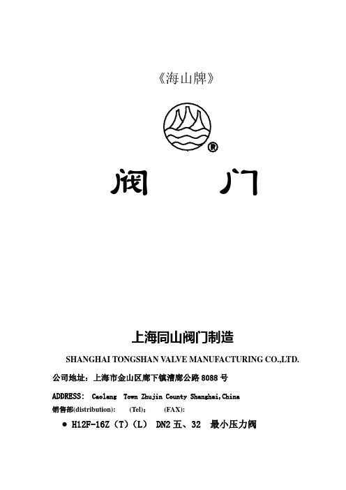
上海同山阀门样本
H1
d0
进 口
出 口
40
57
φ37
G1 1/2"
G1 1/2"
要紧零件材料
零 件
阀 体
阀 瓣
密 封 面
弹 簧
材 料
HT200
LD10
聚四氟乙烯
50CrVA
ZcuZn38Mn2Pb2
ZL101
●.H12F-16Z(T)(L) DN50 最小压力阀
适 应 介 质
使 用 温 度
开 启 压 力 (MPa)
弹簧
材 料
HPb59-1
HPb59-1
50CrVA
●.AK22X-16T DN 20、2五、3二、40 平安阀
适 应 介 质
使 用 温 度
公 称 压 力(MPa)
整 定 压 力(MPa)
空气
≤120℃
—
要紧结构尺寸单位:mm
DN
H
H0
H1
L
d0
S
进 口
出 口
20
138
123
50
38
φ15
35
G3/4"
φ165×6-φ18
φ165×6-φ18
要紧零件材料
零 件
阀 体
阀 瓣
密 封 面
弹 簧
材 料
HT200
LD10
聚四氟乙烯
50CrVA
●.H42F-16ZDN50 最小压力阀
适 应 介 质
使 用 温 度
开 启 压 力 (MPa)
空 气
≤120℃
—
要紧结构尺寸单位:mm
DN
d0
H
H1
L
D
t
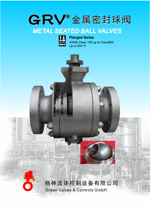
GRV硬密封球阀样本
3. Flow direction for floating mounted type is uni-directional. Trunnion mounted type is fully bi-directional with double-block-and-bleed c a p a b i l i t y.
H
153 195 213 265 153 195 213 265 168 208.5 244 275 167 208 244 275
单位Unit: mm
H1
165 204 217 235 165 204 217 235 141 167 203 242 141 167 202.5 226
Weight Kg 28 54 84 183 30 60 100 204 32 64 122 267 55 97 162 390
金属 密 封球 阀Metal Seated Ball Valves
固 定 球 阀Trunnion Type
16 填料PACKING
FLEXIBLE GRAPHITE
17 填料 压环GLAND RING A182 F304
18 填料 压盖GALND
A182 F304
材料 MATERAL
A182 F316 INCONEL X-750 A182 F316+STL A182 F316+SFNi A182 F316+STL A182 F304+GRAPHITE FLEXIBLE GRAPHITE A194 2H A193 B7 A182 F316 JIS SUS329J1 FLEXIBLE GRAPHITE A182 F316 A182 F304+GRAPHITE A182 F304 FLEXIBLE GRAPHITE A182 F304 A182 F304
派克阀门样本Parker Valve
Female NPT thread (SAE 476) / Female NPT thread (SAE 476)
Visual index 3/2-way ball valves
KH 3/2 (S) p. O42
EO 24° cone end / EO 24° cone end / EO 24° cone end
KHBLOCK p. O51
Ball valve with Flange connection DIN EN 1092-1
2/2-way ball valve for block structure
O6
Catalogue 4100-8/UK
Visual index shut off valves and Line Rupture Valves “LRV”
DV p. O52
Valves
LD p. O53
EO 24° cone end / EO 24° cone end
VDHA p. O54
EO 24° cone end / EO 24° cone end
EO tube end / EO tube end
WV p. O55
ELA/ELAE p. O57
KH-A-S-71 p. O48
Ball valve with SAE Flange connection
KH-B4V-S p. O49
Ball valve with SAE Flange adapter connection
KHB5V-S p. O50
Ball valve with SAE Flange connection ISO 6162 (1/2)
华德比例阀样本[1]
槽逐渐打开,从而控制液流流量,若断电时阀芯靠复位弹簧复位。
当电磁铁未通电时,阀芯(3)由复位弹簧(2)保持中位,如电磁铁A通电,电磁铁推杆直接推动阀芯(3)右移,位移量与电器...2X/...HD-4WRE(E)型阀是靠比例电磁铁操纵的直动型比例换向,用来控制液流的流量和流动方向。
该阀由阀体(1)、一个或两个弹簧(2)型:HD-4WRE(E)(5)、可选内置放大器(6)组成。
电磁铁的控制可通过外部放大器(HD-4WRE)或内置放大器阀芯(3)、一个或两个比例电磁铁—带直动式比例电磁铁的比例换向阀—底板安装—用来控制流量和流动方向—主阀芯弹簧对中—可选带内置放大器,HD-4WREE10型输入可选A1或F1—阀控制通过螺纹连接比例电磁铁实现,线圈可单独拆卸通径压力至流量至6、1031.5MPa180L/minHD-4WRE(E)-2X型电磁比例换向阀北京华德液压工业集团有限责任公司信号成正比,使阀芯(3)的节流—阀和比例放大器配套供应HD-4WRE6...-2X/G24Z4HD-4WREE10...-2X/G24Z4(HD-4WREE)实现。
说明广泛应用于机床、轻工、冶金、矿山、航天等各领域中。
此类阀与HD-4WRE型基本原理相同。
只是这类阀为仅有一个电磁铁"a"的二位比例换向阀。
HD-4WRE比例换向阀采用板式连接,弹簧对中;阀体采用铸造内流道通流能力强,重复精度好;底板安装尺寸与HD-4WRE···A-2X/···型二位四通比例阀a PPTAoB T不带内置放大器比例方向阀HD-4WRE···-2X/···型三位四通比例阀aAa o图形符号B b bHD-4WREE10...A-2X/G24Z4HD-4WRE6...A-2X/G24Z4A-2X/型(二位阀)通用性好;···HD-4WRE 电磁阀相同,二位四通比例阀HD-4WREE···A-2X/···型ab PTAaoB PT 带内置放大器比例方向阀三位四通比例阀HD-4WREE···-2X/···型aB Ao bbGGaGaG接线方式PE12PE型号说明插头连接形式A 2插座连接形式A B12与放大器连接121B说明:对于说明阀芯和,在中位时口至口,以及口及口约有相当于额定值的通流面积4WRA型(外控放大器)与放大器连接PE PE外置HD-VT-VSPA2-1/T1;HD-VT-VSPA2-2/T16-20至+702.8至500矿物油,磷酸质油≤20(为保证阀系统控制性好和寿命长推荐≤10)放大器的电气参数阀的保护型式符合标准DIN40050线圈温度(C°)线圈电阻(Ω)单个电磁铁最大电流(A)名义电压(V)电流消耗放大器电源电压通电率电气形式通径3最大脉冲电流AImax A上限值V 下限值V额定电压VDC在(20C°)时最大热值24<219.435直流电磁铁的电气参数介质温度(C°)工作压力MPa介质粘度(Kg)反向误差(%)重复精度(%)滞环(%)过滤精度液压部分技术参数31.5A、P、B口T口-20至+50≤0.1≤0.05≤0.0525、50、7521通径6可达150IP653100%224直流1031.52110mm /S 8、16、32最大允许流量(L/min)180802.8至3806.36.52.22.44WRE 4WREE 4WRE 4WREE4WRE4WREE vmax 电气部分(放大器与接线盒配套供应)额定流量Q 在ΔP=1MPa时(L/min)重量介质内置放大器HD-VT-4WREE6-2X;HD-VT-4WREE10-2X2.52(μm)HD-4WREE 型内置放大器CD±10V/4...20mA(Diff.)Reference(Diff.)Reference(Actual Value)0V+24V Actual Value Zero±10V/4...20mA(实际值)+24V 0V实际值的参考电位实际值输入±10V/4...20mA(信号输入)U UU IU IU U=≈=≈UU零位振荡器解调器实际值基准电压增益位移传感器七芯插座接口内置放大器阀差动放大器斜坡发生器2)加法器输出端输出端互锁低电压识别电源D EA B PE给定量基准电压24V GND 屏蔽保护电源电压+Ui 0 V -UiD E1)3)内置放大器的方框图/接线图说明:从控制放大器引出的电信号(例如:实际值)不允许用于开关设备的安全保护功能!(请参考欧洲标准“流体技术设备和元件的安全保护要求”—液压技术“EN 982!)1)接点PE 应与温度较低物体及阀体连接;2)斜坡时间可从外部在0到2.5s 调校;同样适用T 和T ;up down 3)零点外部可调.A B F E D C2)3)m 801U 型号4WREE6V321001U L△P SP i n %HD-4WREE 比例电磁阀特性曲线(ν=36×1050泄漏油流量特性曲线(阀芯处于中位)0泄漏油流量L /m i n12100工作压力bar150压力-输入信号特性曲线(V形机能)P=10MPa200250300/St=50°C)通径6和10-62204060100-80-100-20-40-60-5-3-135EENU in %L △P SP i n %21031520406080-80-100-20-40-60-5-3-135EENU in %500泄漏油流量L /m i n12100工作压力bar150200250300210315型号4WREE10V75通径6通径10HD-4WREE 比例电磁阀特性曲线(P=10MPa,ν=36×10通径6ΔP 2010流量L /m i nA 4m A 60A 32120阀的压差为1MPa时,额定流量为16L/min阀的压差为1MPa时,额定流量为8L/min=阀的压差(进口和出口控制台肩的总压降)503、ΔP =3MPa 恒定4、ΔP =5MPa 恒定5、ΔP =10MPa 恒定1、ΔP =1MPa 恒定2、ΔP =2MPa 恒定20304030给定值%/St=50°C)10060708090P B /A T /B T P 或51322-6010802010504030706010090给定值%V 形机能E 和W 形机能3509080302010010207080605040给定值%3040506070流量L /m i n30201040E 和W 形机能10090100V 形机能12/B T /AT或60PB P 458090010201020301050403040506070608070或/AT30流量L /m i n205040PB /B T 阀的压差为1MPa时,额定流量为32L/minP E 和W 形机能10090100V 形机能145807010090110最大容许流量ΔP A m 给定值%A 50125100PB 150A 300180HD-4WREE 比例电磁阀特性曲线(P=10MPa,ν=36×10通径10阀的压差为1MPa时,额定流量为50L/min阀的压差为1MPa时,额定流量为25L/min=阀的压差(进口和出口控制台肩的总压降)503、ΔP =3MPa 恒定4、ΔP =5MPa 恒定5、ΔP =10MPa 恒定1、ΔP =1MPa 恒定2、ΔP =2MPa 恒定2020103040流量L /m i n4030506070给定值%/St=50°C)10060708090PB /AT/B T P或513242-680010802010504030706010090V 形机能E 和W 形机能31259080302010010207080605040给定值%3040506070流量L /m i n755025100E 和W 形机能10090100V 形机能12/B T /AT或150PB P 458090010201020302550403040506070608070或/AT75流量L /m i n/B T 阀的压差为1MPa时,额定流量为50L/minP E 和W 形机能10090100V 形机能32145200175250225275最大容许流量阀芯行程%1000100007500500025105010804020时间ms010203030203040609070信号变化区间%相位°幅值b B-10-15-20-25-301频率Hz103020-3-5020050100-45-135-90-180-225-270信号±100%信号±25%信号±10%HD-4WREE型频率响应特性曲线(P=1MPa,ν=36×10/S,t=50°C)-62通径64/3阀门型机能符号“V”010000750050002520050257560401000204060103020-3-135-10-15-20-25-301-55020050100-45-90-180-315-225-270HD-4WREE型频率响应特性曲线(P=1MPa,ν=36×104/3阀门型机能符号“V”通径10信号变化区间%时间ms阀芯行程%/S,t=50°C)-62幅值b B相位°频率Hz信号±100%信号±25%信号±10%HD-4WREE 型流量(P=1MPa,ν=36×10阀门压差barA /St=50°C)m 502510102010050200400180100300最大容许流量流量L /m i n101102010050200200100/B T P 300或/ATPB 最大容许流量-6280081632阀门在最大开启下的负载曲线标准流量为8L/min、16L/min、32L/min 通径6机能符号“V”需要考虑最大容许流量为80L/min!HD-4WREE型频率响应特性曲线(P=1MPa,ν=36×10通径10/S,t=50°C)-62阀门在最大开启下的负载曲线标准流量为25L/min、50L/min、75L/min 机能符号“V”/B T P A 或/ATPB 阀门压差bar流量L /m i nQ =375L/minmax 需要考虑最大容许流量为180L/min!A Ba ba b型号HD-4WREE6 (2X)P ATBG341/01G342/01G502/010.01/100mm阀固定螺栓:4个M5X40DIN912-10.9M =8.9NmA 安装底板:G341/01(1/4")G342/01(3/8")G502/01(1/2")0.8当无底板安装阀时,要求配合部件表面精加工3比例电磁铁"b"说明:阀在出厂前已经排气6阀的排气孔5标牌4.2黑色插头"B"4.1灰色插头"A"2带有感应位移传感器的比例电磁铁"a"1阀体(油口P、A、B、T)8O形圈9.25X1.7811阀底面油孔尺寸10取下插头所需空间9带一个电磁铁的阀的端堵(两位阀:机能为EA或WA)7感应位移传感器插座;TA PB阀固定螺栓:4个M6X40DIN912-10.9G534/01(3/4")M =15.5NmG67/01(1/2")安装底板:G66/01(3/8")A 0.01/100mm0.8型号HD-4WREE10 (2X)3比例电磁铁"b"说明:阀在出厂前已经排气6阀的排气孔5标牌4.2黑色插头"B"4.1灰色插头"A"2带有感应位移传感器的比例电磁铁"a"1阀体(油口P、A、B、T)8O形圈12X211阀底面油孔尺寸10取下插头所需空间9带一个电磁铁的阀的端堵(两位阀:机能为EA或WA)7感应位移传感器插座;P A TAB TB当无底板安装阀时,要求配合部件表面精加工。
阀门产品样本最新版国标安全阀
阀门产品样本罗浮阀门集团有限公司1、 A21型PN16~40外螺纹连接弹簧封闭微启式安全阀 (1)2、 A21型PN64~100外螺纹连接弹簧封闭微启式安全阀 (2)3、 A21型PN160~320外螺纹连接弹簧封闭微启式安全阀 (3)4、 A27H-10、A27H-16型外螺纹连接弹簧带扳手微启式安全阀 (4)5、 A28H型PN16外螺纹连接弹簧带扳手全启式安全阀 (5)6、 A37H、A43H 型PN16~40双联弹簧带扳手微启式安全阀 (6)7、 A38Y 型PN16~40双联弹簧带扳手全启式安全阀 (8)& A40Y 型PN16~64带散热片弹簧封闭全启式安全阀 (10)9、 A41H、A41Y 型PN16~100弹簧封闭微启式安全阀 (12)10、 A41Y 型 PN160~320弹簧封闭微启式安全阀 (15)11、 A42F、A42Y、KA42Y (抗硫)型 PN16~100弹簧封闭全启式安全阀 (17)12、 42Y 型 PN160~320 弹簧封闭全启式安全阀 (21)13、 WA42Y 型 PN16~40 波纹管弹簧全启式安全阀 (22)14、 A44Y 型PN16~100弹簧封闭带扳手全启式安全阀 (22)15、 A44Y 型PN160~320弹簧封闭带扳手全启式安全阀 (26)16、 A47H 型PN16~40弹簧带扳手微启式安全阀 (27)17、 A48Y 型PN16~100弹簧带扳手全启式安全阀 (29)18、 A48SH 型 PN16~40弹簧带扳手全启式安全阀 (32)19、 A48SH型PN64~160高温高压弹簧带扳手全启式安全阀 (34)20、 A42Y-P55 45V、A62Y-P 55 140V 型气控碟形弹簧安全阀 (36)21、 A68Y 型对焊连接弹簧全启式安全阀 (37)22、 A49H-40 型主安全阀及配套 GA49H-40 型冲量安全阀 (38)23、 A49Y-100、A49Y-100V 型主安全阀及其配套冲量安全阀 (40)24、 A69Y-P54140V 型 DN100 主安全阀及其配套冲量安全阀 (42)25、 A69Y-100、A69Y-100V 型 DN150主安全阀及其配套冲量安全阀 (43)26、 GA41H 型PN16~40杠杆式安全阀 (44)27、 GA42H 型PN16~100单杠杆式安全阀 (45)28、 GA44H 型PN16~64 双杠杆式安全阀 (47)29、 A411F-25、A412F-25、NA42F-25 型内装式安全阀 (48)30、 JA22H-2.5、JA22W-2.5P 型外螺纹连接静重式安全阀 (50)31、 FA72W 型PN10真空负压安全阀 (51)32、 AH42F 型平衡式安全回流阀 (52)33、A61型弹簧微启式安全阀 (53)34、 AY42H PN400 型、LA802Y-600 型安全溢流阀 (55)35、石化专用安全阀 (57)36、AQ-20 型空压机安全阀 (58)37、 LFA46F 型先导式安全阀系列 (59)精选范本1、A21型PN16〜40外螺纹连接弹簧封闭微启式安全阀使用范围:本产品可用于石油、化工行业。
电动阀样本
45216 20664
57226 26152
70650 32287
110390 50449
158962 72646
1908
872
3391
1550
5299
2422
7630
3487
13565 6199
21195 9686
30521 13948
41542 18985
54259 24796
68672 31383
150 200 250 300 400 500 600 700 800 900 1000 1250 1500
价格优势:约为欧美同类产品的 30%。
流量
m3/h
P
P
kg/h
1590
727
2827
1292
4418
2019
6564
3000
11310 5169
17662 8072
25434 11623
34618 15820
重量 kg
24 25 26.5 28 32 38 52 59 79 102 126 203 285 498 604
重量 kg 45 77 100 126 315 417 514 766 978 1111 1332 1553 1774
价格 元 4500 4900 5200 6200 10000 11800 12700 13900 15600 20100 29900 39600 55100 77200 10820
执行机构 传动螺母 传动螺杆 支撑螺杆
A
A
C
关
B
A-C
A
C
B-C
B
A
C
A-C
B
- 1、下载文档前请自行甄别文档内容的完整性,平台不提供额外的编辑、内容补充、找答案等附加服务。
- 2、"仅部分预览"的文档,不可在线预览部分如存在完整性等问题,可反馈申请退款(可完整预览的文档不适用该条件!)。
- 3、如文档侵犯您的权益,请联系客服反馈,我们会尽快为您处理(人工客服工作时间:9:00-18:30)。
一、调节阀系列First、series regulating valve1、型号编制说明The model description:P普通型M密闭型P Normal type M Airtight typeD电动Q气动S手动D Motor-driven Q Pneumatic S Manual风阀高度H Air valve height H风阀宽度W Air valve widthW1 工作温度为-40℃~95℃2工作温度为-55℃~205℃1 the operating temperature -40℃~95℃2 theoperating temperature55℃~205℃D对开式P平行式D Vis-a-vis type P Parallel type创元风量调节阀chuangyuan air volume regulating valve 1.1、型号示例model sample1:CYTD2-1000×500SP 表示创元普通型对开式多叶调节阀,工作温度为-55℃~205℃,宽1000mm,高500mmCYTD2-1000×500SP is Chuangyuan normal vis-a-vis multi-blade regulating valve, the working temperature is -55℃~ 205℃, width is 1000mm, the height is 500mm2、风量调节阀技术参数Air volume regulating valve technical parameters:2.1、风量调节阀框体和叶片采用镀锌钢板制成,无焊点,表面无需涂装;Air volume regulating valve frame and blade made by galvanized steel plates, no weld, the surface doesn’t need paint.2.2、风阀轴承材料为烧结青铜含油轴承,可以耐300℃的高温;The regulating valve bearing material is sintered bronze oiled bearings, can resist high temperature 300℃;2.3、叶片由10×10方形轴连接,轴的材料为45#镀锌钢;Blades are connected by 10×10 square shaft, the material of the bearing is 45# galvanized steel plates 2.4、根据需要可选配可调节风量的执行机构;We can provide implement facility which can regulating the air volume by need.2.5、普通型阀体厚度标准尺寸L=210mm,密闭型阀体厚度标准尺寸L=180mm,也可根据客户需要生产各种特型尺寸;The standard thickness of the normal valve dimension is L=210, the standard thickness of the airtight valve dimension is L=180, customers may also choose a variety of special type size;2.6、风量调节阀的法兰宽度为30mm、40mm,客户可以根据需要选择;The width of the air regulating valve flange is 30mm、40mm,the user can make choice.2.7、密闭阀密封材料为橡胶。
The seal material of the airtight valve is rubber.3、风量调节阀分类以及特点The air volume regulating valve classification and characteristics:3.1、分为普通型风量调节阀、密闭型风量调节阀。
每种又有对开与平行式两种类型以及手动、气动、电动三种驱动方式;The air control valve is divided into normal air volume regulating valve、airtight air volume regulating valve. Each of them has two types, Off-style and parallel style, and they have three driven ways: manual, pneumatic, electric, manual;对开式与平行式选用的一般原则General selection principles of off-style and parallel:(a)当阀门所需调节的管段阻力大,而阀门消耗的阻力小时宜选用对开式,反之则应选用平行式;When tube resistance is big but the valve consumes small resistance, it is better to choose off-type on the contrary should choose parallel;(b)对开式的起始调节性能优于平行式;The off-type regulation is better than parallel style;(c)一般做开关用的风阀宜选用平行式;If the valve used as switch the parallel should be chosen;(d)当安装在两个系统的混合处时,宜选用相同特性的调节阀,且宜为对开式;When the valve installed in the mixture place of the two systems, it is better to choose the same characteristics valve, and off-type is better;(e) 对气流噪声有严格要求的系统宜选配平行式;There are strict requirements on the aerodynamic noise matching system, parallel way should be selected;(客户可根据需要选择相应的方式。
)(Customers can select the appropriate way.)3.2、风量调节阀的特点air volume regulating valve features:(a)风量调节阀的传动方式为连杆传动;Drive transmission mode of the air volume regulating valve is the connecting rods way;(b)普通型调节阀的漏风率不大与2%,密闭型调节阀的漏风率不大与0.5%;The leakage rate of the normal air volume regulating valve is no less than 2%, the leakage rate of the airtight air volume regulating valve is no less than 0.5%;(c)手动和电(气)动阀门一般为顺时针方向关闭,逆时针方向开启;M anual and electric (pneumatic) valve is generally clockwise, counterclockwise op en;3.3、风量调节阀的结构尺寸The air volume regulating valve overall dimension3.3.1、普通型风量调节阀Normal air volume regulating valve结构尺寸the structure dimension:备注:(Note)(1)以上“√”尺寸为常用尺寸,也可根据客户需要生产各种特型尺寸。
(当W尺寸≥1250时,加中间框,叶片分隔。
)Note: The above "√" size is commonly used, but we can also produce various special sizes. (When W size ≥ 1250, add the middle frame, blades separated.)(2)L尺寸为210mm。
The dimension L is 210mm。
3.3.2、密闭型风量调节阀Airtight air volume regulating valve结构尺寸the structure dimension :备注:(Note )(1)以上“√”尺寸为常用尺寸,也可根据客户需要生产各种特型尺寸。
(当W 尺寸≥1250时,加中间框,叶片分隔。
)The above "√" size is commonly used, but we can also produce various special sizes. (When W size ≥ 1250, add the middle frame, blades separated.) (2)L 尺寸为180mm 。
The dimension L is180mm 。
二、防火、排烟阀门Fire、smoke damper1、型号编制说明The model description:风阀高度H Valve height H风阀长度W(圆形阀门以Φ表示)Valve length W(Φ is the sign of circular valve)功能Function控制方式Control way产品名称Product Name1.1、产品名称 the product name :FHF:防火阀;PHFH:排烟防火阀;PYF:排烟阀;PYK:排烟口fire damper PHFH: fire & smoke damper; PYF:smoke exhaust valve ;PYK:smoke exhaust outlet 1.2、控制方式Control way:W:熔断器控制自动关闭;Fuse control automatically turns off;S:手动控制关闭或开启;Manual control closed or open;D:电动控制关闭或开启;Electric control closed or open;Dc:电控电磁铁关闭或开启;Electric solenoid closed or open;Di:电控电机关闭或开启;Electric motor turned on or off;Dq:电控气动机构关闭或开启;Electronically controlled pneumatic facility to close or open;注意:排烟阀没有熔断器控制方式;Note: The smoke exhaust valve does n’t have fuse control;1.3功能 Function:F:具有风量调节功能;With air volume regulating functionY:具有远距离复位功能;With remote reset functionK:具有阀门关闭或开启后阀门位置信号反馈功能;With the position signal feedback function after the valve closed or open valve;注意:排烟防火阀和排烟阀不要求风量调节功能;Note: The smoke &fire damper and smoke exhaust valves do not require air volume control function;1.4型号示例model sample:FHF WS-FK-500×500表示防火阀;具有温感控制功能;手动控制功能;具有风量调节功能;具有信号反馈功能;阀体有效长度为500mm,有效高度为500mm。