09. Time Stamping - CN
冲压模具空步英文缩写

冲压模具空步英文缩写Idle Stroke in Stamping Dies.Definition:In the context of stamping dies, an idle stroke refers to the portion of the die cycle during which the punch is retracted from the workpiece without performing any forming operation. It is also known as the "up stroke" or "return stroke".Purpose:The idle stroke serves several important functions in the stamping process:Retracting the Punch: The idle stroke allows the punch to be withdrawn from the workpiece, creating clearance for the removal of the finished part.Resetting the Die: During the idle stroke, the die components are returned to their original positions, preparing them for the next stamping cycle.Allowing Material Flow: The idle stroke provides time for the workpiece material to flow back to its original shape after being deformed by the punch. This helps minimize springback and ensure dimensional accuracy.Cooling the Die: The idle stroke allows the die components to cool down, preventing excessive wear and thermal damage.Design Considerations:The design of the idle stroke is crucial for theoverall efficiency and effectiveness of the stamping die. Key factors to consider include:Stroke Length: The idle stroke length is determined by the clearance required for part removal and the time needed for material flow and die cooling.Acceleration and Deceleration: The acceleration and deceleration profiles of the idle stroke should becarefully designed to minimize shock and vibration that can damage the die or workpiece.Dwell Time: A dwell time may be incorporated into the idle stroke to allow sufficient time for material flow and die cooling.Lubrication: Proper lubrication is essential to reduce friction and wear during the idle stroke.Optimization:Optimizing the idle stroke can improve stamping productivity and reduce downtime. Strategies for optimization include:Reducing Stroke Length: Minimizing the idle stroke length can reduce cycle time and increase productivity.Smoothing Acceleration and Deceleration: Gradual acceleration and deceleration profiles can reduce shock and vibration, extending the lifespan of the die.Minimizing Dwell Time: Reducing dwell time can improve productivity, but it is important to ensure sufficient time for material flow and die cooling.Using High-Performance Lubricants: Employing high-quality lubricants can reduce friction and wear, leading to longer die life and improved part quality.Conclusion:The idle stroke plays a vital role in stamping dies, ensuring the efficient and accurate production of stamped parts. Its design and optimization are critical for maximizing productivity, minimizing downtime, and extending the lifespan of the die.。
简述数字时间戳及其原理。

简述数字时间戳及其原理。
数字时间戳( Digital(Time-Stamping,DTS)是一种用于证明数据完整性和来源的技术。
它通过将数据与一个精确到毫秒的时间标记相关联,来确保数据的不可篡改性和真实性。
数字时间戳的原理是将数据和时间信息一起加密,生成一个唯一的、不可更改的数字签名。
数字时间戳的工作原理如下:首先,用户需要向时间戳服务器发送要进行时间戳认证的数据。
然后,时间戳服务器会对该数据进行哈希运算,生成一个唯一的哈希值。
接着,时间戳服务器会用自己的私钥对哈希值进行加密,生成一个数字签名。
最后,时间戳服务器将加密后的数字签名和原始数据一起返回给用户。
当用户需要验证数据的真实性时,只需将数据提交给时间戳服务器。
服务器会对数据进行同样的哈希运算,并使用自己的公钥解密数字签名。
如果解密后的哈希值与用户提交的哈希值相同,那么数据就被认为是真实的。
数字时间戳技术通过将数据与精确的时间标记相结合,为数据提供了一种可靠的完整性和来源证明机制。
它在金融、法律、医疗等领域具有广泛的应用前景。
英语语法智慧树知到答案章节测试2023年黑龙江科技大学

第一章测试1.This technique is useful but it has its limitations .()A:错B:对答案:B2.Bankruptcy is a real possibility if sales don’t improve.()A:对B:错答案:A3.Acting (act) on a good idea is better than just having a good idea.()A:对B:错答案:A4.The teacher assigned us a lot of homework, but we had no time for theseassignments (assign).()A:对B:错答案:A5.This is the most effective way to cure your illness.()A:错B:对答案:B6.一个句子按照语法结构可以通过切分法从上到下层层切分为:句子、分句、词组、词和词素五个层次。
()A:错B:对答案:B7.词素是最小的语法单位,也是最小的语义单位,有自由词素和粘附词素两大类。
()A:错B:对答案:B8.名词复数标记-s/es, 名词所属格标记-’s,形容词、副词比较级和最高级标记-er, -est等都属于粘附词素中的派生词缀。
()A:对B:错答案:B9.前缀un-, non-, in-, dis-等都可以表示否定含义,如unfair, nonsmoker,inflame, discover。
()A:错B:对答案:A10.英语的后缀具有较强的语法作用,加在词根上构成派生词,往往不改变词根的基本意义,而是改变了词性,如:-ness, -ment, -ly。
()A:对B:错答案:A第二章测试1.This bag ____ his; he left for Beijing yesterday. ()答案:B2.You need to ____ before posting it. ()A:have the letter stampingB:have the letter stampedC:be stamped your letterD:have the letter to stamp答案:B3.You __________ your children paint on the wall. ()答案:A4.I __________ have had some experiences in dealing with him. ()A:am supposed toB:am bound toC:happen toD:turn out to答案:C5.Before his retirement he _______ catch the early bus every morning. ()A:couldB:wouldC:willD:might答案:B6.A: You complained to the manager, of course?B: No. I asked to speak to himbut he would not come to the phone.A: You should have insisted.()A:错B:对答案:B7.The Great Wall is the fruit of labor, sweat and blood, and embodies thewisdom of the ancient Chinese people.()A:对B:错答案:A8.They shouldn’t be allowed to get away with it. 句中allow是单宾语动词。
DINION IP 5000 MP摄像头浏览器界面手册说明书

Bosch Security Systems
| zh-CHS 3
11 11 11 12 12 13 13 13 13 14 14 14 15 15 16 16 16 16 17 17 17 18 19 19 19 20 20 22 22 22 22 22 23
2015.04 | v1.592 | AM18-Q0678zh
4 zh-CHS |
4.4 4.5 4.6 4.7 5 5.1 5.1.1 5.1.2 5.1.3 5.2 5.2.1 5.2.2 5.3 5.3.1 5.3.2 5.3.3 5.3.4 5.3.5 5.3.6 5.4 5.4.1 5.4.2 5.4.3 5.4.4 5.4.5 5.4.6 5.4.7 5.5 6 6.1 6.1.1 6.1.2 6.1.3 6.1.4 6.1.5
编码器
音频
录像
系统概述
常规设置
标识
命名 ID iSCSI Initiator extension Password
输入密码 Confirm password Date/Time Date format Device date / Device time Device time zone Daylight saving time Time server IP address Time server type Display Stamping Camera name stamping Time stamping Display milliseconds Alarm mode stamping Alarm message
6 zh-CHS |
7.3 7.3.1 7.4 7.4.1 7.4.2 7.4.3 7.4.4 7.5 7.5.1 7.5.2 7.5.3 7.5.4 7.6 7.7 7.8 7.9 7.9.1 7.9.2 7.9.3 7.10 8 8.1 8.1.1 8.1.2 8.1.3 8.1.4 8.1.5 8.1.6 8.1.7 8.1.8 8.1.9 8.2 8.2.1 8.2.2 8.3
证书代码

代码签名 (1.3.6.1.5.5.7.3.3)
时间戳 (1.3.6.1.5.5.7.3.8)
加密文件系统 (1.3.6.1.4.1.311.10.3.4)
服务器身份验证 (1.3.6.1.5.5.7.3.1)
IP 安全终端系统 (1.3.6.1.5.5.7.3.5)
URL=/pki/certs/MicrosoftRootAuthority.crt
服务器身份验证 (1.3.6.1.5.5.7.3.1)
客户端身份验证 (1.3.6.1.5.5.7.3.2)
代码签名 (1.3.6.1.5.5.7.3.3)
代码签名 (1.3.6.1.5.5.7.3.3)
Full Name:
Directory Address:
CN=crl102_0
OU=CRL
CN=ROOTCA
O=OSCCA
C=CN
[2]CRL Distribution Point
Distribution Point Name:
Full Name:
[1]CRL Distribution Point
Distribution Point Name:
Full Name:
URL=/sfsca-crl.crl
[1]CRL Distribution Point
Distribution Point Name:
[3]CRL Distribution Point
Distribution Point Name:
Full Name:
URL=/carl/carl.crl
Pendulum CNT-90XL 脉冲RF计数分析仪数据表说明书
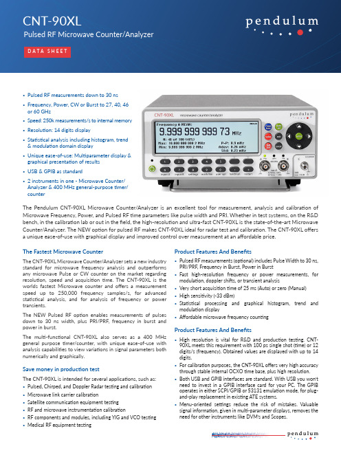
Counter/Analyzer is an excellent tool for measurement, analysis and calibration of Microwave Frequency, Power, and Pulsed RF time parameters like pulse width and PRI. Whether in test systems, on the R&D bench, in the calibration lab or out in the field, the high-resolution and ultra-fast CNT-90XL is the state-of-the-art Microwave Counter/Analyzer. The NEW option for pulsed RF makes CNT-90XL ideal for radar test and calibration. The CNT-90XL offers a unique ease-of-use with graphical display and improved control over measurement at an affordable price.The Fastest Microwave CounterThe CNT-90XL Microwave Counter/Analyzer sets a new industry standard for microwave frequency analysis and outperforms any microwave Pulse or CW counter on the market regarding resolution, speed and acquisition time. The CNT-90XL is the worlds fastest Microwave counter and offers a measurement speed up to 250,000 frequency samples/s, for advanced statistical analysis, and for analysis of frequency or power transients.The NEW Pulsed RF option enables measurements of pulses down to 30 ns width, plus PRI/PRF, frequency in burst and power in burst.The multi-functional CNT-90XL also serves as a 400 MHz general purpose timer/counter, with unique ease-of-use with analysis capabilities to view variations in signal parameters both numerically and graphically.Save money in production testThe CNT-90XL is intended for several applications, such as:• Pulsed, Chirped, and Doppler Radar testing and calibration• Microwave link carrier calibration• Satellite communication equipment testing• RF and microwave instrumentation calibration• RF components and modules, including YIG and VCO testing• Medical RF equipment testing Product Features And Benefits• Pulsed RF measurements (optional) includes Pulse Width to 30 ns, PRI/PRF, Frequency in Burst, Power in Burst• Fast high-resolution frequency or power measurements, for modulation, doppler shifts, or transient analysis• Very short acquisition time of 25 ms (Auto) or zero (Manual)• High sensitivity (-33 dBm)• Statistical processing and graphical histogram, trend and modulation display• Affordable microwave frequency countingProduct Features And Benefits• High resolution is vital for R&D and production testing. CNT-90XL meets this requirement with 100 ps single shot (time) or 12 digits/s (frequency). Obtained values are displayed with up to 14 digits.• For calibration purposes, the CNT-90XL offers very high accuracy through stable internal OCXO time base, plus high resolution.• Both USB and GPIB interfaces are standard. With USB you won’t need to invest in a GPIB interface card for your PC. The GPIB operates in either SCPI/GPIB or 53131 emulation mode, for plug-and-play replacement in existing ATE systems.• Menu-oriented settings reduce the risk of mistakes. Valuable signal information, given in multi-parameter displays, removes the need for other instruments like DVM’s and Scopes.Battery OptionThe CNT-90XL has an optional battery pack with 90 Wh capacity, capable of mains-free operation for at least 4.5 hours. In stand-by mode the battery pack can keep an OCXO warm and running for over 24 hours. Battery operation of a frequency counter/analyzer is valuable in three different applications:• Transportation of high-stability OCXO to maintain stability, which gives instant use at destination without any warm-up time• Battery backup acting as a built in UPS (Uninterrupted Power Supply)TimeView®, Modulat ion Domain Analysis SWThe optional Modulation Domain SW TimeView® is the ultimate tool to view and analyze dynamic frequency changes in real-time, utilizing the high-resolution PC screen, marker read-outs and processing, FFT calculation to find modulation frequencies, ADEV calculation of short-term stability and more.Excellent Graphical PresentationOne of the great features of the CNT-90XL is the graphical display and the menu oriented settings. The non-expert can easily make correct settings without risking costly mistakes. The multi-parameter display shows auxiliary measurement values such as Power level in dBm in Frequency measurements.Measurement values are presented both numerically and graphically. The graphical presentation of results (histograms, trends etc.) gives a much better understanding of the nature of signal jitter. It also provides you with a much better view of changes vs time, from long term trends like slow drift, to fast modulation and transients. Three statistical views of the same data set can be viewed: Numerical, Histogram and Modulation/T rend. It is very easy to capture and toggle between views of the same data.When adjusting a frequency source to given limits, the Limit qualifying tool gives fast and accurate visual guidance. T olerance limit markers are visually displayed and the actual frequency is graphically displayed inside or outside the limit markers. Passing the limits will cause an alarm indication.The graphical display examples below show the frequency changes over time directly on-screen, for example Doppler frequency shift in speed radar sensors, fast power switching, FM or AM. Builtin statistical processing presents numerical stability data and also frequency distribution histograms on-screen for analysis of frequency stability or modulation.Figure 2:Pulse modulated frequency or FSKFigure 3:Generator start-up power settlingFigure 4:Very small AM on carrier is visualizedFigure 5:Numeric statistics screen of the previous AM signalFigure 6:Power step from generator (-30 to -5dBm in 5dBm steps) NOTE: output is turned off shortly betw. power stepsFigure 7:Power step (close up)Figure 1:1kHz FM with 12 ppm modulation depthMeasuring FunctionsFrequency A, B, CRange:Input A, B: 0.002 Hz to 400 MHzInput C: 300 MHz to 27, 40, 46 or 60 GHz Resolution: 12 digits in 1s measuring time Acquisition C: Auto or ManualAcquisition time: 25 ms in Auto (typ.)*Note: Some frequencies may not be acquired correctly with Auto Acquisition. If so, switch to Manual Acquisition instead Aux. Parameters:Input A, B: Vmax, Vmin, Vp-pInput C: Power C in dBm or WFrequency Burst A, BRange:Input A, B: 0.002 Hz to 400 MHzInput C: Requires option 28 - see “Pulsed RF” specs Minimum Burst Duration: Down to 40 ns Minimum Pulses in Burst:Input A or B: 3 (6 above 160 MHz)PRF Range: 0.5 Hz to 1MHzStart Delay: 10 ns to 2sec., 10 ns resolution Aux. Parameter: PRFPeriod A, B (single or average), C (average) Mode: Single, AverageRange:Input A, B: 2.5 ns to 1000 sInput C: 3.3 ns down to 37, 25, 22 or 17 ps Resolution: 100 ps (single); 12 digits/s (avg) Acquisition C: Auto or ManualAcquisition time: 25 ms in Auto (typ.)Aux. Parameters: See Freq. A, B, or C measurements Ratio A/B, B/A, C/A, C/BRange: (10-9) to 1011Input Frequency:Input A, B: 0.1 Hz to 300 MHzInput C: 300 MHz to 27, 40, 46 or 60 GHzAux Parameters: Freq 1, Freq 2Time Interval A to B, B to A, A to A, B to B Range:Normal Calculation: 0ns to +106 sec.Smart Calculation: -106 sec. to +106 sec. Resolution: 100 psMin. Pulse Width: 1.6 nsSmart Calculation: Smart Time Interval to determine sign (A before B or A after B) Positive and Negative Pulse Width A, B Range: 2.3 ns to 106 sec.Min. Pulse Width: 2.3 nsAux. Parameters: Vmax,Vmin, Vp-pRise and Fall Time A, BRange: 1.5 ns to 106 sec.Trigger Levels: 10% and 90% of signal Vp-p Min. Pulse Width: 1.6 nsAux. Parameters: Slew rate, Vmax, Vmin Positive and Negative Duty Factor A, B Range: 0.000001 to 0.999999Freq. Range: 0.1 Hz to 300 MHzAux. parameters: Period, pulse widthPhase A Relative B, B Relative ARange: -180° to +360°Resolution: Single-cycle: 0.001° to 10 kHz, decreasing to 1° >10 MHz. Resolution can be improved via averaging (statistics)Freq. Range: up to 160 MHzAux. Parameters: Freq (A), Va/Vb (in dB)Vmax, Vmin, Vp-p A, BRange: -50 V to +50 V, -5V to +5VRange is limited by the specifi cation for max i nputvoltage without damage (see input A, B)Freq. Range: DC, 1Hz to 300 MHzMode: Vmax, Vmin, Vp-pResolution: 2.5 mVUncertainty (5V range, typical):DC, 1Hz to 1kHz: 1% +15 mV1kHz to 20 MHz: 3% +15 mV20 to 100 MHz: 10% +15 mV100 to 300 MHz: 30% +15 mVAux parameters: Vmin, Vmax, Vp-pTime Stamping A, B, CRaw time stamp data together with pulse countson inputs A, B or C, accessible via GPIB or USBonly.Max Sample Speed: See GPIB specificationsMax Frequency: 160 MHzTimestamp Resolution: 70 psPower CRange:Power: -35 dBm to +10 dBmFrequency: 300 MHz to 27, 40, 46 or 60 GHzDisplay units: dBm (default) or WResolution: 0.01 dBm @100 ms measuring timeAccuracy (typ.): <1dBm to 27 GHz;<2dBm to 40 GHz; <3dBm to 60 GHzAcquisition:Auto or Manual (within ±40 MHz)Acquisition time: 20 to 30 ms in Auto (typ.)Aux.Parameters: Frequency CPulsed RF parameters (Option 28)Pulse ON voltage range:0.4 to 40 GHz: -15 dBm to +13 dBm(-20 dBm typ. to +13 dBm)40 to 46 GHz: -10 dBm (typ.) to +13 dBm46 to 60 GHz: 0 dBm (typ.) to +10 dBmMin ON/OFF ratio: 15 dBPulse WidthRange: 30 ns to 1 sec.Resolution: 200 ps rmsAccuracy: <10 ns+TBE*P_widthPRI (pulse repetition interval)Range: 60 ns to 1 sec.Resolution: 200 ps rmsAccuracy: <2 ns +TBE*PRI*PRF (pulse repetition frequency)Range: 1 Hz to 16.7 MHz (20 MHz typ.)Resolution: (200ps/Meas_time)*PRF HzFrequency in BurstRange: 400 MHz to 60 GHzPulse width: down to 100 nsResolution: (50ps/ √N/Gate_time)*FREQ Hz*Acquisition: ManualPeak Power in BurstRange: - 20dBm to +10 dBmPulse width: down to 50 usAcquisition: ManualResolution: 0.1 dBm < 1ms pulse0.01 dBm>1ms pulse* N = number of RF pulses during total measurement* TBE=number of RF pulses during total measurement (e.g. 6E-8)*Gate=meas. time inside each RF pulseInput and Output SpecificationsInputs A and BFrequency Range:DC-Coupled: DC to 400 MHzAC-Coupled: 10 Hz to 400 MHzImpedance: 1MΩ // 20 pF or 50 Ω (VSWR ≤2:1)Trigger Slope: Positive or negativeMax. Channel Timing Difference: 500 psSensitivity:DC-200 MHz: 15 mVrms200-300 MHz: 25 mVrms300-400 MHz: 35 mVrmsAttenuation: x1, x10Dynamic Range (x1):30 mVp-p to 10 Vp-p within ±5V windowTrigger Level: Read-Out on displayResolution: 3mVUncertainty (x1): ±(15 mV + 1% of trigger level)AUTO T rigger Level: Automatically set to 50% point ofinput signal (10% and 90% for Rise Fall Time)AUTO Hysteresis:Freq. range: 1Hz to 300 MHzTime: Min hysteresis window (hysteresis compensation)Frequency: 40% of input signal amplitude (typ.)Analog LP Filter: Nominal 100 kHz, RC-type.Digital LP Filter:1Hz to 50 MHz cut-off frequencyMax Voltage Without Damage:1M: 350 V (DC + AC pk) to 440 Hz, falling to 12Vrms at 1MHz; 50Ω : 12 VrmsConnector: BNCInput CFreq. Range: 0.3 to 27, 40, 46, 60 GHz dependingon modelOperating input voltage range:0.3 to 18 GHz: -33 to +13 dBm18 to 20 GHz: -29 to +13 dBm20 to 27 GHz: -27 to +13 dBm27 to 40 GHz: -23 to +13 dBm40 to 46 GHz: -17 to +13 dBm46 to 60 GHz: -15 to +10 dBmImpedance: 50Ω nominal, AC coupledVSWR:0.3 to 27 GHz: <2.0:1 (typ.)27 to 46 GHz: <2.5:1 (typ.)46 to 60 GHz: <3.0:1 (typ.)FM tolerance:Manual acq.: 50 MHz p-p; freq C >3.5 GHz30 MHz p-p; freq C <3.5 GHzAuto acq.: 20 MHz p-p; for any freq C andmodulation frequency > 0.1 MHzAM tolerance:Any modulation index (minimum signal must bewithin sensitivity range)Automatic Amplitude Discrimination:10 dB separation between 2 signals within30 MHz, 20 dB otherwiseMax Voltage Without Damage: +25 dBmOverload indication:ON when input C power >+10 dBmConnector:27 and 40 GHz: 2.92 mm sparkplug female46 and 60 GHz: 1.85 mm sparkplug female(all connectors are field replaceable)Rear Panel Inputs and OutputsReference Input: 1, 5, or 10 MHz; 0.1 to 5Vrmssine; impedance ≥ 1kΩReference Output:10 MHz; >1Vrms sine into 50ΩArming Input:Arming of all measuring functionsImpedance: Approx. 1kΩFreq. Range: DC to 80 MHzConnector: BNC© Pendulum Instruments Measuring FunctionsTrigger Hold-OffTime Delay Range: 20 ns to 2sec., 10 ns resolutionExternal Start and Stop ArmingModes: Start and Stop ArmingInput Channels: A, B or E (Ext. Arming input)Max Rep. Rate for Arming Signal:Channel A, B: 160 MHz Channel E: 80 MHzStart Time Delay Range:20 ns to 2sec., 10 ns resolutionStatisticsFunctions: Maximum, Minimum, ΔMax-Min, Mean, Standard Deviation and Allan Deviation Display: Numeric, histograms or trend plots Sample Size: 2 to 2 x 10⁹ samplesLimit Qualifier: OFF or Capture values above/below/inside or outside limitsMeasurement Pacing: 4s to 500 sec.MathematicsFunctions: (K*X+L)/M, (K/X+L)/M or X/M-1. X is current reading and K, L and M areconstants; set via keyboard or as frozen reference value (X 0)Other FunctionsMeasuring Time: 20 ns to 1000 s for Frequency, Burst, PRF, Period Average and Power.Single cycle for other measuring functions Timebase Reference:Internal, External or AutomaticDisplay Hold: Freezes result, until a new measurement is initiated via RestartLimit Alarm: Graphical indication on front panel and/or SRQ via GPIBLimit Values: Lower limit, Upper limitSettings: OFF or Alarm if value is above/below/inside or outside limitsOn Alarm: STOP or CONTINUE Display: Numeric + GraphicStored Instrument Set-ups: 20 instrument setups can be saved/recalled from internalnonvolatile memory. 10 can be user protected.Result Storage: Up to 8 measurements of max 32k samples can be stored in local memory for later downloading.Display: Backlit LCD Graphics screen for menu control, numerical read-out and status information Number of Digits: 14 digits in numerical mode Resolution: 320*97 pixelsGPIB InterfaceCompatibility: IEEE 488.2-1987, SCPI 1999 or 53131A/53132A compatibility mode Interface Functions:SH1, AH1, T6, L4, SR1, RL1, DC1, DT1, E2Max. Measurement Rate:GPIB: 5k readings/s (block mode) 500 readings/s (individual GET trig’ed)T o Internal Memory: 250k readings/sInternal Memory Size: Up to 750k readings.USB InterfaceUSB Version: 2.0 Full speed (11 Mbits/s)CalibrationMode: Closed case, menu controlledCal. Frequencies: 0.1, 1, 5, 10, 1.544 and 2.048 MHzGeneral SpecificationsEnvironmental DataClass: MIL-PRF-28800F, Class 3Operating T emp: 0 °C to +50 °C Storage T emp: -40 °C to +71 °C Humidity: 5%-95% (10 °C to 30 °C)5%-75% (30 °C to 40 °C)5%-45% (40 °C to 50 °C)Altitude: 4 600 mVibration: Random and sinusoidal according to MIL-PRF-28800F, Class 3Shock: Half-sine 30G per MIL-PRF-28800F Bench handlingTransit drop test: According to MIL-PRF-28800F Safety: EN 61010-1, pollution degree 2, meas cat I, CSA C22.2 No 1010-1, CEEMC: EN 61326 (1997); A1 (1998), increased test levels according to EN 50082-2, Group 1, Class B, CEMains power: 90 to 265 Vrms, 45 to 440 Hz, <40 W, <60 W if battery optionDimensions and WeightWidth x Height x Depth:210x90x395 mm (8.25x3.6x15.6 in)Weight: Net 2.7 kg (5.8 lb),Shipping app. 3.5 kg (app. 7.5 lb)Ordering InformationBasic Models CNT-90XL-27G:27 GHz Microwave Counter/Analyzer CNT-90XL-40G:40 GHz Microwave Counter/Analyzer CNT-90XL-46G:46 GHz Microwave Counter/Analyzer CNT-90XL-60G:60 GHz Microwave Counter/AnalyzerTime Base: Medium Stability Oven Time Base;0.06 ppm/month as standardIncluded with Instrument: 3 years product warranty 1,line cord, user documentation on CD, andCertificate of Calibration1The warranty period may be dependent on country.Pulsed RF OptionOption 28: Pulsed RF measurementsTime Base OptionsOption 30/90: Very High Stability Oven Time Base; 0.01 ppm/monthOption 40/90: Ultra High Stability Oven Time Base; 0.003 ppm/monthOption 23/90 Battery UnitBattery Type: Li-Ion, 90 WhExternal DC input: 10 to 18 Vdc; max 6A Operating temp. range: 0 °C to 40 °C Storage: -20 °C to +60 °C, 1 month -20 °C to +45 °C, 3 months -20 °C to +20 °C, 1 yearBattery operating time (at 25°C):ON: >4.5 hoursStand-by: >24 hours Charging:Automatically when AC or ext DC is connected Battery status indicator:On-screen with Low battery warning Weight: 2.3 kg (4.9 lb)Optional AccessoriesOption 22/90: Rack-Mount Kit Option 27: Carrying Case - softOption 27H: Heavy-duty Hard T ransport Case Option 29/90: TimeView Modulation Domain Analysis SW for CNT-90XLOption 90/06: Calibration Certifi cate with Protocol; Oven oscillatorOption 90/00: Calibration Certifi cate with Protocol; Frequency aging/weekOption 95/05: Extended warranty from 3 to 5 yearsOM-90: Users Manual English (printed)PM-90: Programmers Manual English (printed)SM-90: Service Manual English GS-90-EN: Getting Started English GS-90-FR: Getting Started French GS-90-DE: Getting Started GermanTime Base OptionsOption model Standard:30/9040/90Time base type:OCXO OCXO OCXO Uncertainty due to:-Aging per 24h per month per year-T emperature variations: 0˚C to 50˚C 20˚C to 26˚C (typ. values)<5x10⁻⁹(1)<6x10⁻⁸<2x10⁻⁷<5x10⁻⁸<2x10⁻⁸<5x10⁻¹⁰(1)<1x10⁻⁸<5x10⁻⁸<5x10⁻⁹<1x10⁻⁹<3x10⁻¹⁰(1)<3x10⁻⁹<1.5x10⁻⁸<2.5x10⁻⁹<4x10⁻¹⁰Short-term stability: τ =1s (root Allan Variance) τ =10s<1x10⁻¹⁰<1x10⁻¹⁰<1x10-11<1x10-11<5x10-12<5x10-12Power-on stability:Deviation vs. fi nal value after 24 h on time, after a warm-up time of:<1x10-730 min<1x10-810 min<5x10-910 minTypical total uncertainty, for operating temperature 20˚C to 26˚C, at 2σ (95%) confi dence interval:-1 year after calibration -2 years after calibration<2.4x10⁻⁷<4.6x10⁻⁷<0.6x10⁻⁷<1.2x10⁻⁷<1.8x10⁻⁸<3.5x10-81After 1 month of continuous operation。
PKI中数字时间戳技术
第43卷增刊12003年10月大连理工大学学报JournalofDalianUniversityofTechnologyV01.43,S1oct.2003文章编号:1000—8608(2003)S1一S027—03PKI中数字时问戳技术王勇’,朱方金,史清华(山东大学计算机科学与技术学院,山东济南250061)摘要:首先从时间戳的必要性起,叙述了时间戳的基本要求和与之相关的可能出现的问题及解袭这些问题的方法;然后舟绍了时间戳的概惫和取得时间戳的流程;最后着重阐述了保证时问戳的可靠性和匿名性,并减少时阊戳确认时间的方法.关键词:数字时间戳;数字时间戳服务;时间戳权威中图分类号:TP393文献标识码:A0引言随着互联网的快速发展,电子交易已逐渐进入人们的生活,电子交易的安全性也逐渐成为人们关注的主题.目前普遍采用的是公钥基础设施PKI(publickeyinfrastructure)确保电子交易的安全.PKI可以在电子化社会中建立人们之间的信任关系.但是要保证交易的防抵赖,依靠单纯的数字签名技术是无法实现的.因为要防止抵赖,不仅需要对交易数据进行数字签名,还必须保证此交易数据在某一时间之前的存在性.这通常要借助于时问戳来解决.1时间戳产生的必要性1.1电子商务交易的需要在一个典型的Internet交易中,交易双方是通过SSL(securesocketlayer)建立端到端的安全链接,双方在这条安全的通道上进行交易,通过使用SSL,交易数据的私密性、完整性以及发方鉴别都可得到解决.但是如何保证交易的不可否认性,单纯通过SSL是无法实现的,1.2知识产权的需要互联网不但让人分享资源,而且还促进知识的交流.但部分人缺乏保护知识产权的意识,也不尊重别人的创作成果,肆意抄袭别人的作品,甚至据为己有.1.3增强PKl服务PKI数字签名的安全性直接依赖于用户私钥的保密,假如用户私钥意外失密,由该私钥产生的所有数字签名必须作废,可见,数字签名不具备永久验证性.要解决以上问题,就必须找出一个可靠有效的方法去证明资料存在的确实时间.PKI中的时间戳技术可以用于核实网上交易的内容,见证知识产权的诞生,证实网上记录的完整性和真实性,避免网络交易纠纷,从而能有效勰决以上问题.2什么是时问戳数字时问戳可以为任何电子文件或网上交易提供准确的时间证明,并且可以检验出文件或交易的内容自加上时间戳后是否曾被人修改过.电子时问戳就如一个值得信赖的第三者或公证人,为人提供可靠的时间确认服务.数字时间戳技术是数字签名技术的一种变种的应用.在电子商务交易文件中,时间是十分重要的信息.在书面合同中,文件签署的日期和签名一样均是十分重要的防止文件被伪造和篡改的关键性内容.数字时间戳服务DTS(digitaltimestampservice)是网上电子商务安全服务项目之一,能提供电子文件的日期和时间信息的安全保护.时间戳是一个经加密后形成的凭证文档,它包括以下3个部分:(1)需要时间戳的文件的摘要;(2)DTS收到文件的日期和时间;(3)DTS的数字签名.所有电子数据或资料,不论是什么样的格式或内容,都可以加上数字时间戳.这个可靠的时间核证服务可应用于网上商务交易、电子邮件、加密信息、保障知识产权和其他需要准确时问证收稿Et期t2003—06—25.作者筒介:王勇’(1979一),男,硕士生,E-mailtwartgyong@ma[t.sdu.educn.S28大连理工大学学报第43卷明的事务.3时问戳的工作流程数字时间戳的实行,必须要有一个公认的时问机关负责制造及确认时间戳.由于用户桌面时间很容易改变,由该时间产生的时间戳不可信赖,因此需要一个可信任的第三方——时间戳权威TSA(timestampauthority),来提供可信赖的且不可抵赖的时间戳服务.TSA的主要功能是提供可靠的时间信息,证明某份文件(或某条信息)在某个时间(或以前)存在,防止用户在这个时间后伪造数据进行欺骗恬动o].时间戳服务提供商担当着中介者的角色,负责TSA与最终使用者之间的沟通.时问戳服务供应商比较了解行业的特性,因此管理会更为有效,亦更切合使用者的需要.最终用户可以是公司、团体或个别用户,他们向时间戳服务供应商申请服务,通过时间戳服务商的网站或者软件取得数字时间戳.时间戳的工作流程:(1)最终用户希望为其数字文件取得数字时间戳;(2)最终用户用自己的私人密钥为数字文件的散列数值进行数字签名;(3)电脑计算出经数字签名的电子文件的散列数值;(4)独一无二的散列数值经互联网被发送到时问戳服务提供商;(5)时间戳服务提供商将收到的散列数值连同准确的日期时间,以它的私人密钥签发时间戳}(6)时间戳服务提供商将独一无二的时间戳发送给文件主人;(7)时间戳服务提供商保留该时间戳的记录,作为日后查阅及核实使用.4时间戳的可靠性和匿名性数字时间戳技术最需要解决的是可靠性和匿名性.4.1可靠性时间戳产生方案要保证即使时间戳服务是恶意的,电子文档也能被正确的时间签署.目前有两种时间戳技术,一种是基于TSA的技术,一种是基于分布式信任概念的技术.TSA技术是常见的一种技术,以上讨论的就是基于TSA技术的时间戳服务.分布式信任的技术是给一个群体中的很多客户进行签名和时间认证,使得这个群体中所有元素中的任何一个都不能对交易进行否认.要解决可靠性的问题首先要用到数字签名和哈希函数.如果不用哈希函数,那么要将电子文档全都传到时间戳服务商那里,这样在传输过程或者电子文档的存储过程中不能保证电子文档的私密性和安全性.且电子文档的存储也要占很大的空间.所以电子文档在传输过程中要经过哈希函数的处理.用数字签名可以保证双方相互证实彼此的身份.在现实中时间戳的使用有两种情况.一种是绝对的时间戳,一种是相对的时间戳.绝对时间戳给电子文档包含一个和现实生活中一样的真实时间.相对时间戳只要证明某个电子文档是早于另一个文档即可.其中绝对时间戳的取得是假定时间戳服务是一个可信的实体.对于相关的时问戳,一个可信的实体不是必须的,因此这种方法需要一个即使时间戳服务是恶意的,也耍提供一个能签署正确时间的方案.下面介绍两种这样的方案D].4.1.1连接方案时间戳服务能通过一个Ⅳ函数连接所有提交的电子文档的哈希值.第n个文档H.的时间戳文档S—signTSA∞,f。
Pendulum CNT-91 零死时计数器产品说明书
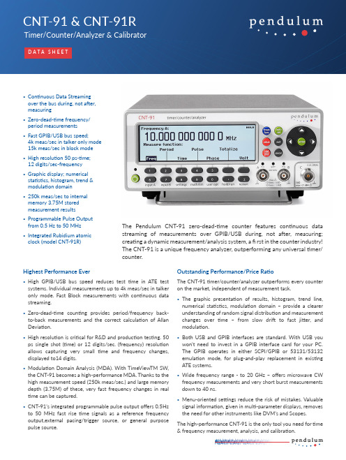
The Pendulum CNT-91 zero-dead-time counter features continuous data streaming of measurements over GPIB/USB during, not after, measuring; creating a dynamic measurement/analysis system, a fi rst in the counter industry! The CNT-91 is a unique frequency analyzer, outperforming any universal timer/ counter.Highest Performance Ever• High GPIB/USB bus speed reduces test time in ATE test systems. Individual measurements up to 4k meas/sec in talker only mode. Fast Block measurements with continuous data streaming.• Z ero-dead-time counting provides period/frequency back-to-back measurements and the correct calculation of Allan Deviation.• H igh resolution is critical for R&D and production testing. 50 ps single shot (time) or 12 digits/sec. (frequency) resolution allows capturing very small time and frequency changes, displayed to14 digits.• M odulation Domain Analysis (MDA). With TimeViewTM SW, the CNT-91 becomes a high-performance MDA. Thanks to the high measurement speed (250k meas/sec.) and large memory depth (3.75M) of these, very fast frequency changes in real time can be captured.• C NT-91’s integrated programmable pulse output offers 0.5Hz to 50 MHz fast rise time signals as a reference frequency output,external pacing/trigger source, or general purpose pulse source.Outstanding Performance/Price RatioThe CNT-91 timer/counter/analyzer outperforms every counter on the market, independent of measurement task.• The graphic presentation of results, histogram, trend line, numerical statistics, modulation domain – provide a clearer understanding of random signal distribution and measurement changes over time – from slow drift to fast jitter, and modulation.• B oth USB and GPIB interfaces are standard. With USB you won’t need to invest in a GPIB interface card for your PC. The GPIB operates in either SCPI/GPIB or 53131/53132 emulation mode, for plug-and-play replacement in existing ATE systems.• W ide frequency range - to 20 GHz – offers microwave CW frequency measurements and very short burst measurements down to 40 ns.• M enu-oriented settings reduce the risk of mistakes. Valuable signal information, given in multi-parameter displays, removes the need for other instruments like DVM’s and Scopes.The high-performance CNT-91 is the only tool you need for time & frequency measurement, analysis, and calibration.CNT-91R Frequency Calibrator/AnalyzerThe CNT-91R Frequency Calibrator/Analyzer is an all-inclusive high performance calibrator of frequency sources, that combines the high resolution measurements and advanced analysis of CNT-91, with a built-in ultra-stable Rubidium atomic reference clock. Its compact format, and its short warm-up time, makes the CNT-91R an ideal transportable one-box frequency calibrator/ analyzer.Excellent Graphical PresentationOne of the great features of the CNT-91 is the graphical display and the menu oriented settings. The non-expert can easily make correct settings without risking costly mistakes.The multi-parameter display with auxiliary measurement values such as Vmax/Vmin/Vp-p in frequency measurements, and frequency/ attenuation/phase, eliminates the need for extra test instruments and provides direct answers to frequently asked questions, like “What is the attenuation and phase shift of this fi lter?” Measurement values are presented both numerically and graphically. The graphical presentation of results (histograms, trends etc.) gives a much better understanding of the nature of jitter. It also provides you with a much better view of changes vs time, from slow drift to fast modulation (trend plot). Three statistical views of the same data set can be viewed: Numerical, Histogram and T rend. It is very easy to capture and toggle between views of the same data (see fi gure 4, 5 & 6).When adjusting a frequency source to given limits, the graphic display gives fast and accurate visual calibration guidance.CNT-91/91R vs CNT-90 selection chartFeature CNT-91/91R CNT-90 Graphic display of trend, histogram,modulation domain yes yes Frequency resolution12 digits/sec12 digits/sec Time resolution (single shot)50 ps100 ps Voltage resolution1mV 2.5mVMeasurement speed to internal memory250k meas/sec3.75M results 250k meas/sec 750k resultsTalker only output (GPIB/USB)4k meas/sec no Individually triggered measurements650/sec500/sec Block transfer speed15k meas/sec5k meas/sec Freq, period, time, phase, volt, duty c,pulse w, rise time yes yesT otalize, TIE yes no Programmable pulse output yes no Continuous measurements yes no Timebase CNT-91OCXO (opt)OCXO (opt) Timebase CNT-91R OCXO (opt)OCXO (opt)Figure 1:Display showing phase value, frequency, attenuation Va/Vb,and auxiliary parameters.Figure 2:Measure function selection menu, shown with measured results.Figure 3:Input parameter setting menu shown with measured result.Figure 4:Display showing different statistical parameters viewed at thesame time.Figure 5:Display showing the trend (signal over time) of sampled data.Figure 6:The same result as in Figure 5, now displayed as a histogram.Measuring FunctionsAll measurements are displayed with a large main parameter value and smaller auxiliary parameter values (with less resolution). Some measurements are only available as auxiliary parameters.Frequency A, B, CMode: Normal, back-to-back Range:• Input A, B: 0.002 Hz to 400 MHz• Input C (option): Up to 3, 8, 15 or 20 GHz Resolution: 12 digits in 1s measuring time (normal), 11 digits in 1s meas time (back-to-back)Aux. Parameter (A, B): Vmax, Vmin, Vp-pFrequency Burst A, B, C (opt. 14/14B)Frequency and PRF of repetitive burst signals can be measured without external control signal and with selectable start arming delay.Functions: Frequency in burst (in Hz); PRF (in Hz)Range: Input A, B, C: See Frequency spec.Minimum Burst Duration: Down to 40 ns Minimum Pulses in Burst:• Input A or B: 3 (6 above 160 MHz)• Input C: 3 x prescaler factor PRF Range: 0.5 Hz to 1MHzStart Delay: 10 ns to 2sec., 10 ns resolution Aux. Parameter: PRFPeriod A, B, CMode: Single, average, back-to-back Range:• Input A, B: 2.5 ns to 1000 sec. (single, average)• Input C (option): 10 ns down to 330, 125, 70 or 50 psResolution: 100 ps (single); 12 digits/s (avg)Aux. Parameter (A, B): Vmax, Vmin, Vp-pRatio A/B, B/A, C/A, C/BRange: (10-9) to 1011Input Frequency:• Input A, B: 0.1 Hz to 400 MHz• Input C (option): Up to 3, 8, 15 or 20 GHz Aux Parameters: Freq 1, Freq 2Time Interval A to B, B to A, A to A, B to BRange:• Normal Calculation: 0ns to +106 sec.• Smart Calculation: -106 sec. to +106 sec.Resolution: 50 ps (single)Min. Pulse Width: 1.6 nsSmart Calculation: Smart Time Interval to determine sign (A before B or A after B)Positive and Negative Pulse Width A, BRange: 2.3 ns to 106 sec.Min. Pulse Width: 2.3 nsAux. Parameters: Vmax,Vmin, Vp-pRise and Fall Time A, BRange: 1.5 ns to 106 sec.Trigger Levels: 10% and 90% of signal Vp-p Min. Pulse Width: 1.6 nsAux. Parameters: Slew rate, Vmax, VminTime Interval Error (TIE) A, BNormalized period back-to-back measurements, calculated as TIE(k) = k •TREF - ΣTi, when T i = individual period back-to-back and T REF = reference period valuePositive and Negative Duty Factor A, BRange: 0.000001 to 0.999999Freq. Range: 0.1 Hz to 300 MHz Aux. parameters: Period, pulse widthPhase A Relative B, B Relative ARange: -180° to +360°Resolution: Single-cycle: 0.001° to 10 kHz, decreasing to 1° >10 MHz. Resolution can be improved via averaging (statistics)Freq. Range: up to 160 MHzAux. Parameters: Freq (A), Va/Vb (in dB)T otalize A, BMode: T ot A, T ot B, T ot A+B, T ot A-B, T ot A/B Range: 1 to 1010 counts Freq range: up to 160 MHzStart control: Manual, start armingStop control: Manual, stop arming, timed Aux. Parameters: Other T ot functionsVmax, Vmin, Vp-p A, BRange: -50 V to +50 V, -5V to +5VRange is limited by the specifi cation for max input voltage without damage (see input A, B)Freq. Range: DC, 1Hz to 300 MHz Mode: Vmax, Vmin, Vp-p Resolution: 1 mVUncertainty (5V range, typical):• DC, 1Hz to 1kHz: 1% +15 mV • 1kHz to 20 MHz: 3% +15 mV • 20 to 100 MHz: 10% +15 mV • 100 to 300 MHz: 30% +15 mV Aux parameters: Vmin, Vmax, Vp-pTime stamping A, B, CRaw time stamp data together with pulse counts on inputs A, B or C, accessible via GPIB or USB only.Max Sample Speed: See GPIB specifications Max Frequency: 160 MHz Timestamp Resolution: 35 psInput and Output Specifi cationsInputs A and BFrequency Range:• DC-Coupled: DC to 400 MHz • AC-Coupled: 10 Hz to 400 MHz Impedance: 1MΩ // 20 pF or 50 Ω (VSWR ≤2:1)Trigger Slope: Positive or negativeMax. Channel Timing Difference: 500 ps Sensitivity:• DC-200 MHz: 15 mVrms • 200-300 MHz: 25 mVrms • 300-400 MHz: 35 mVrms Attenuation: x1, x10Dynamic Range (x1): 30 mV p-p to 10 V p-p within ±5V windowTrigger Level: Read-Out on display • Resolution: 1mV• Uncertainty (x1): ±(15 mV + 1% of trigger level)• AUTO T rigger Level: T rigger level isautomatically set to 50% point of input signal (10% and 90% for Rise/Fall Time)AUTO Hysteresis:• Freq. range: 1Hz to 300 MHz• Time: Min hysteresis window (hysteresis compensation)• Frequency: One third of input signal amplitudeAnalog LP Filter: Nominal 100kHz, RC-type.Digital LP Filter: 1Hz to 50 MHz cut-off frequencyMax Voltage Without Damage:•1MΩ: 350 V (DC + AC pk) to 440 Hz, falling to 12 Vrms at 1MHz.• 50 Ω: 12 Vrms Connector: BNCInput C (Option 13)Operating Input Voltage Range:• 100 to 200 MHz: 100 mVrms to 2.5Vrms (typ.)• 200 to 300 MHz: 40 mVrms to 2.5Vrms (typ.)• 300 to 500 MHz: 20 mVrms to 2.5Vrms • 0.5 to 3.0 GHz: 10 mVrms to 2.5Vrms • 3.0 to 4.5 GHz: 20 mVrms to 2.5Vrms • 4.5 to 6.0 GHz: 40 mVrms to 2.5Vrms • 6.0 to 8 GHz: 80 mVrms to 2.5Vrms Prescaler Factor: 256Impedance: 50 Ω nominal, VSWR <2.5:1Max Voltage without Damage: 2.5Vrms Connector: Type N FemaleInput C (Option 14)Freq. Range: 0.25 to 15 GHz Operating Input Voltage Range:• 250 to 500 MHz: -21 to +21 dBm • 0.5 to 15 GHz: -27 to +21 dBm Prescaler Factor: 128Impedance: 50 Ω nominal, VSWR <2.0:1AM tolerance: > 90% within sensitivity range Max Voltage Without Damage: +21 dBm Connector: Type N FemaleInput C (Option 14B)Freq. Range: 0.25 to 20 GHz (opt. 14B)Operating input voltage range:Prescaler Factor: 128Impedance: 50 Ω nominal, VSWR <2.0:1AM tolerance: > 90% within sensitivity range Max Voltage Without Damage: +27 dBm Connector: Type precision N FemaleRear Panel Inputs and OutputsReference Input: 1, 5, or 10 MHz; 0.1 to 5Vrms sine; impedance ≥1kΩReference Output: 10 MHz; >1Vrms sine into 50 ΩArming Input:Arming of all measuring functions • Impedance: Approx. 1kΩ• Freq. Range: DC to 80 MHz Rear Panel Measurement Inputs:A, B, C (opt. 11/90)Impedance: 1MΩ//50 pF or 50 Ω (VSWR ≤ 2:1)Connectors: SMA female for rear input C, BNC for all other inputs/outputsAuxiliary FunctionsTrigger Hold-OffTime Delay Range: 20 ns to 2sec., 10 ns resolutionExternal Start and Stop ArmingModes: Start, Stop, Start and Stop Arming Input Channels: A, B or E-rear panelMax Rep. Rate for Arming Signal:• Channel A,B: 160 MHz • Channel E: 80 MHzStart Time Delay Range: 20 ns to 2sec., 10 ns resolutionStatisticsFunctions: Maximum, Minimum, Mean, Δmax-Min, Standard Deviation and Allan Deviation Display: Numeric, histograms or trend plots Sample Size: 2 to 2 x 10⁹ samplesLimit Qualifier: OFF or Capture values above/below/inside or outside limits Measurement Pacing:• Pacing Time Range: 4μs to 500 sec.MathematicsFunctions: (K*X+L)/M and (K/X+L)/M. X iscurrent reading and K, L and M are constants; set via keyboard or as frozen reference value (X 0)Other FunctionsMeasuring Time: 20 ns to 1000 sec. for Frequency, Burst, and Period Average. Single cycle for other measuring functionsTimebase Reference: Internal, External or AutomaticDisplay Hold: Freezes result, until a new measurement is initiated via RestartLimit Alarm: Graphical indication on front panel and/or SRQ via GPIB• Limit Values: Lower limit, Upper limit • Settings: OFF or Alarm if value is above/below/inside or outside limits • On Alarm: STOP or CONTINUE • Display: Numeric + GraphicStored Instrument Set-ups: 20 instrument setups can be saved/recalled from internal non-volatile memory. 10 can be user protected.Result Storage: Up to 8 measurements of max 32k samples can be stored in local memory for later downloading.Display: Backlit LCD Graphics screen for menu control, numerical read-out and status information • Number of Digits: 14 digits in numerical mode • Resolution: 320*97 pixelsGPIB InterfaceCompatibility: IEEE 488.2-1987, SCPI 1999, 53131A/53132A compatibility modeInterface Functions: SH1, AH1, T6, L4, SR1, RL1, DC1, DT1, E2Max. Measurement Rate:• GPIB: 15k readings/s (block mode)• 4k readings/s (talker only mode)• 650 readings/s (individual GET trig’ed)T o Internal Memory: 250k readings/sInternal Memory Size: Up to 3.75M readings.USB InterfaceUSB Version: 2.0 Full speed (11 Mbits/s)CalibrationMode: Closed case, electronic calibration, menu controlledCal. Frequencies: 0.1, 1, 5, 10, 1.544 and 2.048 MHzGeneral Specifi cationsEnvironmental DataClass: MIL-PRF-28800F, Class 3Operating T emp:• 0°C to +50°C (CNT-91)• 0°C to +45°C (CNT-91R)Storage T emp: -40°C to +71°C Humidity: 5%-95% (10°C to 30°C) 5%-75% (30°C to 40°C) 5%-45% (40°C to 50°C)Altitude: 4,600 metersVibration: Random and sinusoidal according to MIL-PRF-28800F, Class 3Shock: Half-sine 30G per MIL-PRF-28800F; Bench handlingTransit drop test: Heavy-duty transport case and soft carrying case tested according to MIL-PRF-28800FReliability: MTBF 30,000 hours (calculated)Safety: EN 61010-1, pollution degree 2, meas cat I, CSA C22.2 No 1010-1, CEEMC: EN 61326 (1997); A1 (1998), increased test levels according to EN 50082-2, Group 1, Class B, CETime Base OptionsOption model STD 19/9030/9040/90CNT-91R Time base type:Standard OCXO OCXO OCXO Rubidium Uncertainty due to:-Aging per 24h per month per year-T emperature variations: 0˚C to 50˚C 20˚C to 26˚C (typ. values) n/a <5x10⁻⁷<5x10⁻⁶<1x10⁻⁵<3x10⁻⁶<5x10⁻⁹(1)<6x10⁻⁸<2x10⁻⁷<5x10⁻⁸<2x10⁻⁸<5x10⁻¹⁰(1)<1x10⁻⁸<5x10⁻⁸<5x10⁻⁹<1x10⁻⁹<3x10⁻¹⁰(1)<3x10⁻⁹<1.5x10⁻⁸<2.5x10⁻⁹<4x10⁻¹⁰n/a<5x10-11( 2)<2x10⁻¹⁰ (3)<1x10⁻¹⁰<1.2x10⁻¹¹Short-term stability: τ =1s (root Allan Variance) τ =10snotspecified <1x10⁻¹⁰<1x10⁻¹⁰<1x10-11<1x10-11<5x10-12<5x10-12<1x10-11<3x10-12Power-on stability:Deviation vs. fi nal value after 24 h on time, after a warm-up time of:n/a 30 min<1x10-730 min<1x10-810 min<5x10-910 min<5x10-1012 minTypical total uncertainty, for operating temperature 20˚C to 26˚C, at 2σ (95%) confi dence interval:-1 year after calibration -2 years after calibration<7x10⁻⁶<1.2x10⁻⁵<2.4x10⁻⁷<4.6x10⁻⁷<0.6x10⁻⁷<1.2x10⁻⁷<1.8x10⁻⁸<3.5x10⁻⁸<2.5x10⁻¹⁰<5x10⁻¹⁰(4)© Pendulum Instruments 20201After 1 month of continuous operation 2After 3 months of continuous operation 3After 1st year, aging during 1st year: <5x10⁻¹⁰; long term< 2 x 10⁻⁹ / 10 years 4After 1 year of operation. Uncertainty <6x10⁻¹⁰ the first year of operation 5T emperature variation 0˚C to 45˚C for CNT-91RPower RequirementsBasic Version: 90 to 265 Vrms, 45 to 440 Hz, <40 T-91R:• Warm-up (12 minutes): 90 to 265 Vrms, 45 to 440 Hz, <60 W•Operating: 90 to 265 Vrms, 45 to 440 Hz, <50 WDimensions and WeightWidth x Height x Depth: 210 x 90 x 395 mm (8.25 x 3.6 x 15.6 in)Weight: Net 2.7 kg (5.8 lb), Shipping app. 3.5 kg (app. 7.5 lb)Ordering InformationBasic ModelCNT-91: 400 MHz, 50 ps Timer/Counter including Standard Time BaseCNT-91R: 400 MHz, 50 ps Timer/Counter including Rubidium Time BaseIncluded with Instrument: 3 years productwarranty, line cord, user documentation on CD, and Certifi cate of CalibrationInput Frequency Options• Option 10: 3 GHz Input C • Option 13: 8 GHz Input C • Option 14: 15 GHz Input C •Option 14B: 20 GHz Input COscillator OptionsOption 19/90: Medium Stability Oven Time Base; 0.06 ppm/monthOption 30/90: Very High Stability Oven Time Base; 0.01 ppm/monthOption 40/90: Ultra High Stability Oven Time Base; 0.003 ppm/monthOptional Accessories• Option 11/90: Rear Panel Inputs (replaces front panel inputs)• Option 22/90: Rack-Mount Kit • Option 27: Carrying Case - soft• Option 27H: Heavy-duty Hard T ransport Case• Option 29/91: TimeView 3 Modulation Domain Analysis SW for CNT-91/CNT-91R •Option 90/01: Calibration Certifi cate with Protocol; Standard oscillator•Option 90/06: Calibration Certifi cate with Protocol; Oven oscillator• Option 90/07: (CNT-91R only) Calibration Certificate with Protocol; Rubidium oscillator • Option 90/00: Calibration Certifi cate with Protocol; Hold-over frequency aging/week • Option 95/05: Extended warranty from 3 to 5 years• OM-90: Users Manual English (printed)• PM-90: Programmers Manual English (printed)• SM-90: Service Manual English • GS-90-EN: Getting Started English • GS-90-FR: Getting Started French •GS-90-DE: Getting Started German。
- 1、下载文档前请自行甄别文档内容的完整性,平台不提供额外的编辑、内容补充、找答案等附加服务。
- 2、"仅部分预览"的文档,不可在线预览部分如存在完整性等问题,可反馈申请退款(可完整预览的文档不适用该条件!)。
- 3、如文档侵犯您的权益,请联系客服反馈,我们会尽快为您处理(人工客服工作时间:9:00-18:30)。
7
Control Expert中的系统时间戳(续)
Operator Stations
System Servers
Modicon M580
Modicon X80 Remote I/O
来源
- 专用的 ERT 模块 - ERIO配置中的任何 IO 模块 - 来源彼此是独立的
OFS 服务器
- 直接访问来源 - 传送时间戳数据 - 与OPC DA 协议一致
记录缓冲区存储这些数据. ● PLC 应用程序把PLC原始记录数据转换成用户格式的记录并存储他们. ● 监控应用程序使用这些用户格式的记录.
M580 Configuration V1.0
Schneider Electric | Industry Business | Training | October 12, 2020
- 任何 I/O 变量可以打上时间戳 - PLC 内部变量扫描时间
可用的
-方案可兼容冗余配置 -可以在PLC级冗余或SCADA级冗余或二者兼有
M580 Configuration V1.0
Schneider Electric | Industry Business | Training | October 12, 2020
Schneider Electric | Industry Business | Training | October 12, 2020
3
Control Expert中的应用式时间戳
● 应用式时间戳给PLC应用程序提供时间戳事件缓冲区,目的是为了让第 三方SCADA不通过OFS/OPC DA的接口也能访问.
2
Control Expert中的时间戳
● 在Control Expert 中实现时间戳有两个可用的方案, 他们都很容易实现, 并且几乎可以在任何环境下被选择使用.
● 应用式 ● 系统
系统的和可适用的时间戳模式是运行在PAC中的相同Control Expert应用程序 所独有的.
M580 Configuration V1.0
8
系统时间戳益处
● 这里有许多系统时间戳的益处:
● 无需PLC编程 ● 在时间戳模块和客户端之间直接通信. 如果时间戳模块在Modicon X80远程
I/O子站中, PLC的通信带宽不被占用. ● 在过程(时间戳模块) 和客户端 (SCADA)之间数据(I/O 值)的一致性. ● 与每个时间戳事件相关的时间质量信息. ● 在正常操作条件下无事件丢失:
SCADA
- 兼容任何 SCADA (符合OPC DA客户端规则) - 兼容任何报警任务 - 针对Vijeo Citect 进行优化
M580 Configuration V1.0
Schneider Electric | Industry Business | Training | October 12, 2020
Schneider Electric | Industry Business | Training | October 12, 2020
9
ቤተ መጻሕፍቲ ባይዱ
系统时间戳局限性
● 任何方案都有其限制,注意如下项:
● 内部PLC变量可以使用源时间戳方案来标记时间戳. ● 无转换沿选择: 事件检测是基于值变化沿(上升和下降)进行处理的. ● 一个Modicon X80 以太网RIO 子站支持最多36个专家模块. BMX ERT 1604T 模
● 用户可以把从时间戳事件缓冲区中读取的事件的格式转换为专门针对第 三方SCADA的用户格式.
M580 Configuration V1.0
Schneider Electric | Industry Business | Training | October 12, 2020
4
Control Expert中的应用式适用时间戳
●A buffer is available to store the events in 每个时间戳模块中都有存储事 件的缓冲区. 当这个缓冲区满了事件存储就会停止. ● 每一个离散量I/O的上升和下降沿转换都将被存储. ● 支持PLC的热备或冗余的SCADA.
M580 Configuration V1.0
● 一个事件就是一个由时间戳模块所侦测到的离散量 I/O 值的变化.
● 应用式时间戳提供一个一致的SOE (事件序列), 由时间源标识了时间戳.
● 时间戳事件被如下所述的方式管理:
● 每个时间戳模块在本地缓冲区中记录事件. ● PLC 应用程序从模块的本地缓冲区中访问时间戳事件 ,并且在PLC原始数据
SCADA.
Modicon M580
Modicon X80 Remote I/O
M580 Configuration V1.0
Schneider Electric | Industry Business | Training | October 12, 2020
6
Control Expert中的系统时间戳(续)
Operator Stations
System Servers
Modicon M580
Modicon X80 Remote I/O
简单的
- 无需 PLC 或 SCADA 编程 - 时间戳变量作为有规律的数据被管理 (象DCS) - 即插即用方案
可扩展的 (3 可能的来源)
-ERT模块可以精确到1 ms分辨率 -CRA 子站可以到10 ms 分辨率
5
Control Expert中的系统时间戳
● 系统时间戳提供一致的SOE (事件序列 ), 由时间源标识了时间戳.
● SOE 在报警汇总或客户端的SOE页面 上显示 (例如SCADA).
Operator Stations
System Servers
● 每一个SOE中时间戳事件的源头是由时 间戳模块所侦测出的一个离散量 I/O的 值变化, 这个事件经过OFS直接传输给
M580 配置
时间戳 V1.1
时间戳
章节一览
● 时间戳介绍 ● 组件 ● 时间同步 ● BMX ERT 1604 T ● 软件实现
M580 Configuration V1.0
Schneider Electric | Industry Business | Training | October 12, 2020