Removed_调整杠杆说明书()
10K Lowrise LR10000 杠杆抬高机器人说明书

INSTALLATIONd OPERATIONand OPERATION MANUAL10K LOWRISE READ THIS INSTRUCTION MANUAL THOROUGHLY 10K LOWRISELR10000READ THIS INSTRUCTION MANUAL THOROUGHLY BEFORE INSTALLING, OPERATING, SERVICING OR MAINTAINING THE LIFT. SAVE THIS MANUAL.DEC2010 REV.A 6-36536500 MILLCREEK DRIVE,MISSISSAUGA, ONTARIO L5N 2W6TEL: 905-826-8600 * FAX: 905-826-7800TABLE OF CONTENTSTABLE OF CONTENTS (2)1.0 SAFETY AND OPERATING INSTRUCTIONS (3)2.0 SAFETY WARNING DECALS (6)3.0 GENERAL SPECIFICATIONS (8)Figure 1 - Overall Specifications (9)4.0 SHIPPING CONTENTS (10)5.0 TOOLS REQUIRED FOR INSTALLATION (10)6.0 INSTALLATION INSTRUCTIONS (11)6.1 BAY LAYOUT – SURFACE MOUNT (12)Figure 2 - Bay Layout – Surface Mount (12)6.2 UNPACKING THE LIFT (13)7.0 HYDRAULIC CONNECTIONS (13)7.1 ANCHORING PROCEDURES (13)Figure 3 - Anchoring Steps (14)8.0 BLEEDING PROCEDURE (15)8.1 FINAL CHECK OF ASSEMBLED LIST (15)8.2 OPERATION TEST WITH VEHICLE (16)9.0 LIFT OPERATION (16)Before Lifting: (16)Raising the Lift: (16)Lowering the Lift: (16)After Lowering: (17)10.0 RECOMMENDED MAINTANANCE (17)Inspect Regularly for: (17)10.1 MAINTANANCE SCHEDULE (17)11.0 TROUBLE SHOOTING (18)12.0 LIFT ASSEMBLY (19)12.1 LIFT PARTS LIST (19)13.0 POWER PACK ASSEMBLY (20)13.1 POWER PACK PARTS LIST (20)14.0 AVAILABLE ACCESSORIES (22)Figure 4 – Square Rubber Pad, Part No. 6-2776 (Set of 4) (22)Figure 5 – Pump Stand Assembly, Part No. 22573 (22)Figure 6 – Pump Stand Bolt Down 84”, Part No. 3-1027 (23)1.0 SAFETY AND OPERATING INSTRUCTIONS IMPORTANT SAFETY INSTRUCTIONSWhen using your garage equipment , basic safety precautions should always be followed, including the following:1. Read all instructions2. Care must be taken as burns can occur from touching hot parts3. Do not operate equipment with a damaged cord or if the equipment has beendropped or damaged – until it has been examined by a qualified person.4. Do not let a cord hang over the edge of the table, bench , or counter or come incontact with hot manifolds or moving fan blades.5. If an extension cord is necessary, a cord with a current rating equal to or morethan that of the equipment should be used. Cord rated for less current that theequipment may pverheat. Care should be taken to arrange the cord so that it will not be tripped over or pulled.6. Always unplug equipment from electrical outlet when not in use. Never use thecord to pull the plug from the outlet. Grasp plug and pull to disconnect.7. Let the equipment cool completely before putting away. Loop cord loosely aroundequipment when storing.8. To reduce the risk of fire, do not operate equipment in the vicinity of opencontainers of flammable liquids ( gasoline).9. Adequate ventilation should be provided when working on operating internalcombustion engines.10. K eep hair, loose clothing , fingers, and all parts of body away from moving parts.11. T o reduce the risk of electric shock, do not ise on wet surfaces or expose to rain.12. U se only as described in this manual. Use only manufacturer’s recommendedattachments.13. A LWAYS WEAR SAFETY GLASSES. Everyday eye glasses only have impactresistant lenses, they are not safety glasses.SAVE THESE INSTRUCTIONSWhen using this lift, basic safety precautions should always be followed, including the following:1. Thoroughly read all instructions in this manual and on the lift before installing,operating, servicing or maintaining the lift.2. Inspect the lift daily. Do not operate lift if it malfunctions or if problems have beenencountered.3. Never attempt to overload the lift. The manufacturer’s rated capacity is shown onthe identification label. Do not override the operating controls or the warranty will be void.4. Only trained and authorized personnel should operate the lift. Do not allowcustomers or bystanders to operate the lift or be in the lift area.5. Caution! Never work under the lift unless the mechanical safety locks areengaged.6. Always keep the lift area free of obstruction and debris. Grease and oil spillsshould always be cleaned up immediately.7. Never lift a vehicle with passengers inside.8. Before lowering the lift check the area for any obstructions.9. To protect against risk of fire, do not operate lift in the vicinity of open containersof flammable liquids.10. Adequate ventilation should be provided when working on internal combustionengines.11. Do not remove hydraulic fittings while under pressure.12. Only replace parts with genuine lift manufacturer supplied parts.SAVE THESE INSTRUCTIONSFor additional safety instructions regarding lifting, lift types, warning labels, preparing to lift, vehicle spotting, vehicle lifting, maintaining load stability, emergency stop procedures, vehicle lowering, lift limitations, lift maintenance, good shop practices, installation, operator training, and owner/employer responsibilities, please refer to “Lifting It Right” (ALI/SM) “Safety Tips” (ALI/ST) and vehicle lift points for service garage lifting SAE J2184.For additional instructions on general requirements for lift operation, please refer to “Automotive Lift-Safety Requirements For Operation, Inspection and Maintenance” (ANSI/ALI ALOIM).Installation shall be performed in accordance with ANSO/ALI ALIS, SafetyRequirements for Installation and Service of Automotive Lifts.ATTENTION! This lift is intended for indoor installation only. It is prohibited to install this product outdoors. Operating environment temperature range should be 41 – 104 °F (5 – 40 °C). Failure to adhere will result in desertification, loss of warranty, and possible damage to the equipment.2.0 SAFETY WARNING DECALSBe sure the operator is aware and understands all safety warning labels and followsthem accordingly.CAUTION TAPE LOCATIONSNOTE: CAUTION TAPE IDENTIFIES POSSIBLE TRIP HAZARDS WHEN THE LIFT IS LOWERED AND NOT IN USE. ENSURE THAT THIS TAPE IS REPLACED WHEN WORN ORREMOVED.3.0 GENERAL SPECIFICATIONSCapacity: 10000 lbs. 4536 kg Overall Width: 85” 2159 mm Overall Length: 83” 2108 mm Lowered Height: 3-7/8” 98 mm Raised Height: 21½” 546 mm Power Requirements:115 Volts AC, 1 Ph., 60 Hz.Figure 1 - Overall Specifications4.0 SHIPPING CONTENTSOverall Weight: 900lb / 408kg1 – Lifting frame assembly with cylinders attached1 – Pump box including:1 – Pumping unit assembly4 - 1/4” x 1 bolts with nuts & washers (Pump Mount)8 – ¾” x 5 ½” anchor bolts with nuts & washers (Frame Mount)1 – Tee fitting1 – Automotive lift safety tips1 – ALI manual “Lifting it Right”1 – Installation and Operation manual1 – Parts box including:4 – Height adapters4 – Height extensions2 – ¼”x29” hydraulic hose1 – 3/8” x 20’hydralic hose1 – Pumping unit mounting standMissing PartsIt is important to notify the delivery carrier immediately if any parts are damages or missing from shipment.5.0 TOOLS REQUIRED FOR INSTALLATION•16ft. Measuring Tape• Chalk Line•Rotary Hammer Drill•3/4” diameter Masonry Drill Bit• Hammer•SAE Wrenches and Ratchet Set• 2ft. Level• 4ft. Level• Crow Bar•12ft. Step Ladder• Side Cutters• Screwdrivers•4” x 4” Wooden Blocks (for unpacking)6.0 INSTALLATION INSTRUCTIONSWhen the lift arrives on site, please read the owner’s manual completely and make sure the installation instructions are fully understood. Check the contents of the hardware and accessory boxes to make sure no parts are missing and no freight damages exist before starting installation. Gather all the tools listed above and make sure the installation instructions are fully understood before commencing with the installation. IMPORTANT:It is the user’s responsibility to provide a satisfactory installation area for the lift. Lifts should only be installed on level concrete floors with a minimum thickness of five 4 1/4” or 115 mm. Concrete must have a steel reinforcing with a minimum strength of 3000 psi or 21 MPa and should be aged thirty (30) days prior to installation. Maximum slope must not exceed 1/16” per foot.Always pay special attention to the condition of the concrete such as age, cracking, chipping, and levelness. Please consult the architect, contractor or engineer if doubt exists as to the strength and feasibility of the floor to enable proper lift installation and operation.It is the user’s responsibility to provide all wiring for electrical hook-up prior to installation and to insure that the electrical installation conforms to local building codes. Where required, it is the user’s responsibility to provide an electrical isolation switch located in close proximity to the lift that will enable emergency stop capability and isolate electrical power from the lift for any servicing requirements.6.1 BAY LAYOUT – SURFACE MOUNTFigure 2 - Bay Layout – Surface MountNOTE: LAYOUT SHOWN WITH OPTION LINE COVER KIT EAK0299T13A6.2 UNPACKING THE LIFTRemove the metal strapping from the main structure package and slide the liftshipping skid. Open the accessory box and check the contents of the box.1. Position unit on a flat floor allowing a minimum of 6 feet from center of lift to sideobstructions and 12 feet from center of lift to front or rear obstructions. (Lift cylinder is on front end of lift.) Recommended overhead clearance is a minimum97 inches ceiling providing 25 inches for the maximum lift height and 6 feet forthe supported vehicle. For vehicles taller than 6 feet it is recommended that the user provides additional overhead clearance or a shut off mechanism to stop the lift from raising the vehicle too high.2. Remove pumping unit from box and install on pump stand.7.0 HYDRAULIC CONNECTIONSNOTE: When working with hydraulics it is important to keep all components clean.1. Select a position best suited for the power pack.2. Remove the breather filler cap and fill with 11 liters / 3 Gal. of ISO 32 10 weighthydraulic oil.3. Reinstall the breather filler cap onto the Power Unit.4. Connect the 90° elbow fitting (9/16” JIC-M, 3/8” JIC-M) with ‘O’ ring, to thehydraulic outlet port on the valve assembly of the power pack. The 90° elbow fitting is located in a hardware kit.5. Connect 11' (3353 mm) long hydraulic hose (female end) to the opposite end ofthe 90° elbow fitting.6. Locate the opposite (male) end of the 11' (3353 mm) long hydraulic hose.Connect to the central end of the swivel tee.7. Connect the male ends from both 29” long hydraulic hoses to the swivel tee sideends. Locate the opposite (female) ends of both 29” long hydraulic hoses and connect them to the inlet ports of the lift, which are located on the corresponding hydraulic cylinders.8. Tighten the hydraulic line in place so that it runs along the floor giving it a lowprofile.7.1 ANCHORING PROCEDURESNOTE: Check operation of lift (up/down) before anchoring the lift.1. Using a rotary hammer drill and a 3/4” concrete bit, drill through the floor at eachanchor bolt location. Make sure that the 3/4” concrete drill bit is in good condition.2. Clean out the drilling dust from the holes3. Assemble the nut and washer onto the supplied ¾” x 5 ½” long wedge anchorbolts. A minimum of six threads must be visible below the surface of the nut.4. Hammer in the anchors until they make contact with the base plate. Handtighten all anchor bolts. Remove any bolt assembly that does not grip concrete firmly and open expansion sleeve before reinstalling.5. Inspect to make certain lift sits firmly on floor. There should be no twisting orrocking motion in the base unit.6. Torque all anchor bolts to 75 ft-lbs.7. Position the power pack in the final desired location. Using a rotary hammer drilland a 1/4” concrete bit, drill four (4) holes and anchor the power pack stand to the floor using anchor bolts located in the hardware kit.8. Install the optional line covers to protect hydraulic hoses, refer to section 7.29. With all anchor bolts torqued as specified operate the lift checking its fulloperation.If anchor bolts do not tighten to 75 ft-lbs OR project more than 2 ¼” above the concrete surface, the concrete should be replaced by an appropriate concrete pad.(Consult Product Manufacturer / Supplier for further details.)Figure 3 - Anchoring Steps7.2 LINE COVER INSTALLATION (OPTIONAL)NOTE: FLOOR COVERS ARE DESIGNED TO SUPPORT FOOT TRAFFICAND TOOL BOXES UNDER 300LBS. ANY VEHICLE TRAFFIC WILL CAUSE DAMAGE TO THE LINE COVERS.1. Position the power pack in the location shown in the Bay layout Figure 22. Use the combination of straight (2-2736) and angled (2-2734 and 2-2733) linecovers provided in the options line cover kit EAK0299T13 to cover the hosesfrom the structure to the power pack. Any excess hydraulic hose should be coiled and zip tied to the power pack stand to avoid trip hazards.3. The angled line covers 2-2733 and 2-2734 will need to be cut at the cut lineshown in figure 2.4. Using a ¼” concrete drill bit, drill and fasten the line covers to the floor using the¼” x 1” long nail in anchors provided. The number beside the line coversrepresent the quantity of fasteners required to secure that side. Ensure that theline covers are sitting securely on the floor.NOTE: If the lift is shimmed to a point where the line covers do not sit flush due to interference with hoses, the line covers can be heated with a heat gun and then placed over the hoses for a cleaner look.8.0 BLEEDING PROCEDURE1. Press the up control button and raise the lift 10” (254mm) above the ground.2. Lower the lift to the ground and hold the down button until lift fully reaches theground.3. Repeat these steps 3-4 times to completely bleed the system of air. Check the liftfor hydraulic leaks at all connections.4. After bleeding, it is recommended that the filter assembly fitting (between thehydraulic hose and the power pack be cleaned. Place the fitting on a workbench and use an air gun to blow through the filter in the opposite direction to flow from the lift.8.1 FINAL CHECK OF ASSEMBLED LIFT1. Check for hydraulic leaks. ____2. Ensure all safety lock mechanisms are working correctly. ____3. Re-check level of decks. ____4. Check all fasteners, tighten if necessary. ____5. Operate lift to full stroke then lower to ground while checkingfor proper functionality. ____6. Ensure Customer Care Kit is complete and given to operator. ____a. Operation Manual____b. ANSI / ALI Lift It Right Manual ____c. ANSI / ALI Safety Tip CARD ____d. ANSI / ALI ALIS safety Requirements for Installationand Service of Automotive Lifts ____e. ANDI / ALI Quick Reference Guide ____7. Train end user on operation of the lift. ____8.2 OPERATION TEST WITH VEHICLE1. Lower lift to ground.2. Drive vehicle on to lift such that the lift’s contact frame is properly aligned with themanufacturer’s recommended lifting points for that vehicle.3. Raise lift to and lower onto first, second, and third lock positions during full rise toensure all locks are working correctly.4. Check lowering speed and smooth decent rate.5. Lower lift to ground and drive vehicle off lift.If any problems occur during the final checkout or operation of the lift please contact customer service at 1-800-268-7959.9.0 LIFT OPERATIONOperators of this lift should be trained by authorized personnel.Before Lifting:1. After making certain lift is in the fully lowered position, drive the vehicle into thebay and position it with the wheel in front of the superstructure.NOTE: The center of gravity of the vehicle should be centered on the liftingstructure. Refer to the "Lifting it Right" and "Vehicle lifting points quick referenceGuide" ALI/LP Guide provided. SAE J2184DO NOT TURN STEERING WHEEL WHILE TIRES ARE CROSSING2. Check to make certain car is fairly well centered left to right on lift.Raising the Lift:1. Hold toggle switch on pumping unit in “ON” position until locking leg drops ontoone of the three lifting height locking positions.2. Rock vehicle to check for stability.3. Lower the vehicle onto the mechanical locks.Lowering the Lift:1. After making certain lifting area is clear of people, electric cords, hoses, etc.,raise lift past next the safety lock to full height to disengage locking device.2. Press the lowering handle slowly until the lift is in its fully collapsed position..After Lowering:1. Drive car off lift without turning steering wheel while tires are crossing the lift.10.0 RECOMMENDED MAINTANANCEInspect Regularly for:a. Overload cracks in welds and metal fatigue.b. Misalignment of working parts.c. Hydraulic leaks.d. Low fluid level in pump reservoir. DO NOT use automatic transmission fluid.Use only petroleum based ISO 32-10 weight hydraulic oil.e. Lubricate all moving parts.f. Check locking latch for smooth and proper operation.10.1 MAINTANANCE SCHEDULEDaily:1. Check all hydraulic lines and fittings for pinch points , damage , cracks or leaks2. Check all electrical wiring for pinch points , cracks or damage3. Check all moving parts for uneven or excessive wear4. Repair or replace all damaged, defective, worn or broken componentsimmediately.5. Check the telescopic arms for movement. Clean any grease or oil from the liftingadapters.6. Raise and lower the lift at the beginning of each shift, without a vehicle on, toverify the lift is leveled and operating properly.7. Check the operation of the mechanical safety lock and release mechanism. If anydamage or malfunction is found, discontinue using the lift until repair isperformed.Weekly:1. Check and adjust hydraulic level.Every Two Months:1. Clean and re-grease hinge pins.Every Year:Inspect lift as per Automotive Lift Operation, Inspection and Maintenance(ALOIM).Every Two Years:Change hydraulic fluid.LUBRICATION:Where grease is required multi-purpose lithium grease.Where lubricating oil is required > multi-purpose SAE 30 lubricating oil.Where hydraulic oil is required > ISO 32 10W - non detergent hydraulic oil.11.0 TROUBLE SHOOTING1) Motor does not run:A. Breaker tripped or fuse blown.B. Motor thermal overload tripped. Wait for overload to cool.C. Defective control switch. Replace switch.D. Faulty wiring connections. Call electrician.2) Motor runs but the lift will not hold a load.A. A foreign object under check valve. Push handle down and push “raise”switch. Foreign matter should release under pressure.B. Remove check valve. Clean ball and seat and replace the nut.C. Oil level low, check oil reservoir. With lift cylinder (cylinders) in the downposition, pump reservoir should be full.3) Motor runs but the lift picks up partial load only.A. Lift is overloaded. Check capacity of lift and weight of vehicle.B. Relief valve setting is too low. Remove back hex cap on pump and adjustvalve clockwise.C. Hydraulic seals damaged (call customer service for instructions 1-800-266-7959)..4) Lift makes groaning sound when raising or lowering.A. Bleed cylinder manually.B. Add an ounce of oil to the air side of the piston.12.0 LIFT ASSEMBLYNOTE: Only replace parts with genuine lift manufacturers supplied parts12.1 LIFT PARTS LISTItem Part No. Description QTY.1 1-3368 3/8” x 19” x 22-1/2” Rubber Pad 42 2-2569HeightExtension Adapter 44”Height Extension Adapter 43 2-25704-1/2”4 6-1379 3/4” x 5-1/2” Anchor Bolt 45 1-3806 7/8” x 2-3/4” Piston Top Axle 26 2-2561 1/4” x 29” Hydraulic Hose M-F 2Assembly 2Cylinder7 3-10688 6-3516 F Pipe x F Pipe Swivel Tee 6-4-4 19 1-3374 Plastic Lug Nut Box 4restrictor 210 6-4018Flow11 1-3805 3/4” x 2-7/16” Pin 212 3-1066 Lock Leg Assembly 114 2-2566 11' High Pressure Hose 13-1026 Pump Stand Bolt Down Standard 1* Not shown in figure.13.0 POWER PACK ASSEMBLYNOTE: Only replace parts with genuine lift manufacturer’s supplied parts13.1 POWER PACK PARTS LISTAssembly No. Part No. Description1 6-2298 BOLT, 5/16” - 24” X 2-3/4” LG2 6-0774 COUPLING (4 POST POWER PACK)3 6-2157 PLUMBING PLUG 5/16” SAE4 6-2158 SEAL SHAFT 0.5X1X.25.338X.625X.065 6-2159WASHER6 62300 CORDSET 16/3 SJO 8FT 115V PLUG7 6-2156 WIRING ASSEMBLY AC 1PH FENNER8 6-2301 PACKAGE PLUG 9/16” SAE9 6-2157 PLUMBING PLUG 9/16 SAEMAGNET10 6-2162PLUMBING11 6-2302 ELECTRICAL STAKON NUT12 6-2164 SCREW TAPTITE TORX13 6-2165 COVER ASY SUCTIONINLETCLAMPHOSESEADJ.14 6-216615 6-2303 ELECTRIC CORD GRIP 3/4"NPT3/4"PIPENUTELECTRIC16 6-230417 6-1087 VALVE CARTRIDGE CHECK18 6-2305 VALVE LOAD DELAY19 6-2167 NUT 3/4”-16x1” HEX .2520 6-2168 WASHER 3/4” INT TOOTH21 6-1108 RELEASE HANDLE ASS’Y22 6-3782 END HEAD UNIV.23 6-2311 ELECT. REDUCER WASHER.35MMM6X124 6-2169SHCS,25 6-2170 WASHER 1/4 LC HI-COLLRMOTOR(2781-BC)115/230V,1PH,1HP26 6-2600RESERVOIRSCREW27 6-1091BREATHERFILLER28 6-137629 6-0884 INLET HOSE/FILTER ASS'Y30 6-1089 RELIEF VALVE CAP31 6-3783 TANK 2.0 GAL WHITE32 6-1846 CABLE TIE 8” LONG WHITERV1933 6-131934 6-2153 COMPRESSION TUBE NUT35 6-2154 COMP. TUBE SLEEVE36 6-3786 RETURN TUBE 1/2 OD 90 DEGO-RING37 6-0875RESERVOIR38 6-2306 PUMP ASS’Y 0.8 SHORT SPLINE.48X.063X.4239 6-2151SPRING40 6-0880 VALVE CARTRIGE RELEASE MANUAL41 6-2156 MICROSWITCH W/SNAP LID W-20042 6-2161 PLUMB. PLUG 3/8NPT43 6-3466 GROUNDING SCREW, #8-32 X 1/2"DECAL44 6-399614.0 AVAILABLE ACCESSORIESFigure 4 – Square Rubber Pad, Part No. 6-2776 (Set of 4)Figure 5 – Pump Stand Assembly, Part No. 22573Figure 6 – Pump Stand Bolt Down 84”, Part No. 3-1027EAK0299T13A Line Coverkit。
杠杆表使用作业指导书

1.0 目的指导和规范使用人员正确使用和维护杠杆表,确保使用时输出的结果准确有效,达到测量的准确度。
2.0 适用范围适用于公司所有使用杠杆表的岗位。
3.0 定义杠杆表是利用杠杆-齿轮传动机构,将尺寸变化为指针角位移,并指示出长度尺度数值的计量器具,用于测量工件几何形状误差和相互位置正确性。
4.0 职责:4.1 品质部:4.1.1 测量中心:负责量/检具回厂后的验收、领用登记造册、内外校计划的制定及周期检定/校准的执行、坏损量具和检具内部维修、报废判定及统计,监督各使用部门正确使用量具和检具等;4.1.2 各部品管:负责本部门领用的量/检具的日常点检保养、送校等;负责监督稽核量/检具使用保养是否规范;4.2 采购部:负责量/检具采购、退货及对接量/检具专业外校、维修厂商等;4.3 各使用部门:负责本部领用的量/检具的日常使用、点检维护、送校。
5.0 工作流程:5.1 杠杆表结构图5.2 常见杠杆表5.3 杠杆表的使用方法5.3.1使用前的准备工作5.3.1.1杠杆表使用前必须做好检查工作,当有其中一条不能满足时都必须进行更换;A.检查杠杆表的稳定性,取一块表,目视表盘,用手指轻推表的测杆,观察表针读数是否稳定。
B.旋转表盘使“0”位对准指针。
C.检查杠杆表的准确度,用手指反复轻推测杆,检查指针是否能回到“0”位。
5.3.1.2根据所选表架适合规格的轴套,并将其牢固拧在表体上,否则松动易造成表的损坏。
5.3.1.3检查表架各部分功能;A.检查表架上的两个联接螺母是否能拧紧。
B.检查磁力表座的锁紧开关是否能正常工作,可靠。
5.3.2 杠杆表装在表架上的夹持部位应尽量靠近连接销的根部,同时不能影响表盘旋转。
5.4 测量5.4.1 平面测量:调整杠杆表测量的角度以及表架杆的长度和角度,使表的测杆轴线应尽可能垂直工件尺寸变动的方向,在该方向与被测要素接触,接触时指针的压缩量一般为0.02-0.05mm;测量时,测杆轴线尽可能与被测量平面平行,如下图1所示,若出现下图2所示的做法,则会出现不可避免的测量误差,该测量误差Δ=A(1-cosa)[其中A为杠杆表的读数,α为测杆轴线与测量平面之间的夹角],α角度越小误差也相对越小,通用情况下α≤15°为宜,当测量一些特殊工件α角度较大时按下表1换算得出实际测量结果。
海港自由工具 1.5 吨重量限制杠杆斧头说明书

Visit our website at: Emailourtechnicalsupportat:********************************Weight Capacity 1.5 Tons (3,000 lb.)Maximum Height 14-1/4″Minimum Height3-1/8″Meets 2005 ANSI/ASME PALD standards.When unpacking, make sure that the product is intact and undamaged. If any parts are missing or broken, please call 1-888-866-5797 as soon as possible.Copyright © 2014 by Harbor Freight T ools ®. All rights reserved.No portion of this manual or any artwork contained herein may be reproduced in any shape or form without the express written consent of Harbor Freight T ools. Diagrams within this manual may not be drawn proportionally. Due to continuing improvements, actual product may differ slightly from the product described herein.T ools required for assembly and service may not be included.Read this material before using this product.Failure to do so can result in serious injury.SAVE THIS MANUAL.IMPORTANT SAFETY INFORMATION1. Study, understand, and follow all instructionsbefore operating this device.2. Do not exceed rated capacity.3. Use only on hard, level surfaces.4. Lifting device only. Immediately after lifting,support the vehicle with appropriate means.5. Do not move or dolly the vehicle while on the jack.6. Failure to heed these markings may result inpersonal injury and/or property damage.7. Lift only areas of the vehicle as specifiedby the vehicle manufacturer.8. No alterations shall be made to this product.9. Never work on, under or around a loadsupported only by this device.10. Do not adjust safety valve.11. Wear ANSI-approved safety goggles andheavy-duty work gloves during use.12. Keep clear of load while lifting and lowering.13. Lower load slowly.14. Apply parking brake and chocktires before lifting vehicle.15. Lift vehicle only at manufacturerrecommended locations. 16. Inspect before every use; do not useif parts are loose or damaged.17. Do not use for aircraft purposes.18. The warnings, precautions, and instructionsdiscussed in this manual cannot cover allpossible conditions and situations that may occur.The operator must understand that common sense and caution are factors, which cannot be built into this product, but must be supplied by the operator.19. WARNING: The brass components of this productcontain lead, a chemical known to the Stateof California to cause cancer and birth defectsor other reproductive harm. (California Health& Safety Code § 25249.5, et seq.)20. WARNING: This product contains di (2-ethylhexyl)phthalate (DEHP), a chemical known to the Stateof California to cause cancer and birth defectsor other reproductive harm. (California Health& Safety Code § 25249.5, et seq.) IMPORTANT! Before first use:Check hydraulic oil level and fill to 1/4″ below theFill Plug hole as needed as stated on page 4. Thoroughly test the Jack for proper operation.If it does not work properly, bleed air from its hydraulic system as stated on page 4.SAVE THESE INSTRUCTIONS.Page 2For technical questions, please call 1-888-866-5797.Item 62496Page 3For technical questions, please call 1-888-866-5797.Item 62496manual including all text under subheadings therein before set up or use of this product.Note: For additional information regarding the parts listed in the following pages, refer to Parts Lists and Assembly Diagram on page .FunctionsSaddle PadSaddleHandleHandleSocketLifting ArmRear CasterCarry HandleFigure AFill PlugCover Screw for Safety Valve. Do not open or adjust.Figure B: Hydraulic Unitmanual including all text under subheadings therein before set up or use of this product. Tool Set UpAttaching the Handle1. Fasten the Upper Handle to the Lower Handle.2. Loosen the Set Screw and insert theassembled Handle into the Handle Socket.3. Tighten the Set Screw.Bleeding1. Remove the Fill Plug.2. Insert the Handle into the Handle Socketto operate the Release Valve.3. Turn the Handle counterclockwise to open the valve.4. Pump the Handle up and down quickly severaltimes to purge air from the system.5. Replace the Fill Plug.Adding Oil1. Remove Fill Plug. See Figure B: Hydraulic Unit.2. Add high grade hydraulic fluid into the Fill Plughole slowly until the oil is 1/4″ below the fill hole.Note: Do not touch the Handle when adding the hydraulic oil.3. Replace the Fill Plug.Page 4For technical questions, please call 1-888-866-5797.Item 62496General Operating InstructionsLiftingPark vehicle on a flat, level, solid, surface safely away from oncoming traffic. Turn off the vehicle’s engine. Place the vehicle’s transmission in “PARK” (if automatic) or in its lowest gear (if manual). Set the vehicle’s emergency brake. Then, chock the wheels that are not being lifted.1. Turn the Handle counterclockwise to lower the Jack.Once the Jack is fully lowered, turn theHandle firmly clockwise to close it.2. Carefully position the Saddle of the Jack underthe vehicle manufacturer’s recommended liftingpoint. (See vehicle manufacturer’s owner’smanual for location of frame lifting point.)3. Pump the Handle until the top of the Jack’s Saddlehas nearly reached the vehicle lifting point. Positionthe Saddle directly under the vehicle’s lifting point. 4. To lift the vehicle, pump the Handle ofthe Jack. Use smooth, full strokes.5. Once the vehicle is raised, slide a jack stand ofappropriate capacity (not included) under a properlifting point referred to in the vehicle owner’smanual. Always use two jack stands, position themat the same point on each side of the vehicle.WARNING! The rated capacity of jack stands is per pair, not the individual capacities combined unless specifically noted on the product by the jack stand manufacturer. Do not exceed rated jack stand capacity. Ensure that the vehicle support points are fully seatedin the saddle of both jack stands. Use a matched pairof jack stands per vehicle to support one end only. Failure to do so may result in the load suddenly falling, which may cause personal injury and/or property damage.6. Center the vehicle’s lifting point(s) on the saddle ofthe jack stand(s). Set the jack stand(s) to the same height according to the manufacturer’s instructions,making sure that they lock securely into position.7. Slowly turn the Handle counterclockwise to lowerthe vehicle onto the saddle(s) of the jack stand(s).Then, turn the Handle firmly clockwise to close it.Lowering1. Carefully remove all tools, parts, etc.from under the vehicle.2. Position the Saddle under the lifting point.Turn the Handle firmly clockwise and raise load high enough to clear the jack stands,then carefully remove jack stands.3. Slowly turn the Handle counterclockwise(never more than 1/2 full turn) to lowerthe vehicle onto the ground.4. Lower the Jack completely. Then, store in asafe, dry location out of reach of children.5. To prevent accidents, turn off the tool anddisconnect its power supply after use. Clean, then store the tool indoors out of children’s reach.Page 5For technical questions, please call 1-888-866-5797. Item 62496Procedures not specifically explained in this manual mustbe performed only by a qualified technician.TO PREVENT SERIOUS INJURY FROM TOOL FAILURE:Do not use damaged equipment. If abnormal noise or vibration occurs, have the problem corrected before further use. Cleaning, Maintenance, and Lubrication1. Before each use, inspect the general conditionof the Jack. Check for broken, cracked, or bentparts, loose or missing parts, and any conditionthat may affect the proper operation of the product.If a problem occurs, have the problem correctedbefore further use.Do not use damaged equipment.2. Before each use, thoroughly test the Jackfor proper operation prior to its actual use.If the Jack appears not to be working properly,follow Bleeding instructions on page 4.3. Wipe dry with a clean cloth. Then, store theJack in a safe, dry location out of reach ofchildren and other non-authorized people.4. Change the hydraulic oil at leastonce every three years:A. With the Jack fully lowered, remove theFill Plug on the top of the Ram.B. Tip the Jack to allow the old hydraulic oilto drain out of the Housing completely,and dispose of the old hydraulic oil inaccordance with local regulations.C. With the Jack upright, completely fill the Ramwith a high quality hydraulic oil (not included)until the oil is 1/4″ below the fill hole.D. Open the valve by turning the Handlecounterclockwise and pump the Handleto bleed air from the system.E. Recheck oil level and re-fill as needed.F. Reinstall the Fill Plug.Page 6For technical questions, please call 1-888-866-5797.Item 62496Page 7For technical questions, please call 1-888-866-5797.Item 62496Record Product’s Serial Number Here:Note: If product has no serial number, record month and year of purchase instead.Note: Replacement parts are not available for this item.TroubleshootingTO PREVENT SERIOUS INJURY:Use caution when troubleshooting a malfunctioning jack. Stay well clear of the supported load.Completely resolve all problems before use. If the solutions presented in the Troubleshooting guide do not solve the problem, have a qualified technician inspect and repair the jack before use.After the jack is repaired: Test it carefully without a load by raising and lowering it fully, checking for proper operation, BEFORE RETURNING THE JACK TO OPERATION.DO NOT USE A DAMAGED OR MALFUNCTIONING JACK!POSSIBLE SYMPTOMSPROBABLE SOLUTION (Make certain that the jack is not supporting a load while attempting a solution.)Jack will not lift at its weight capacitySaddle lowers under loadPump stroke feels spongySaddle will not lift all the wayHandlemoves up when jack is under loadOil leakingfrom Fill Plug X X Check that Release Valve is fully closed. Bleed air from the system.X XXValves may be blocked and may not close fully. To flush the valves:1. Lower the Saddle and securely close the Release Valve.2. Manually lift the saddle several inches.3. Open the release valve and force the saddle down as quickly as possible.XXXJack may be low on oil. Check the oil level and refill if needed.Jack may require bleeding - see instructions on page Bleeding on page 4.XUnit may have too much hydraulic oil inside, check fluid level and adjust if needed.Harbor Freight Tools Co. makes every effort to assure that its products meet high quality and durability standards, and warrants to the original purchaser that this product is free from defects in materials and workmanship for the period of 90 days from the date of purchase. This warranty does not apply to damage due directly or indirectly,to misuse, abuse, negligence or accidents, repairs or alterations outside our facilities, criminal activity, improper installation, normal wear and tear, or to lack of maintenance. We shall in no event be liable for death, injuriesto persons or property, or for incidental, contingent, special or consequential damages arising from the use ofour product. Some states do not allow the exclusion or limitation of incidental or consequential damages, so the above limitation of exclusion may not apply to you. THIS WARRANTY IS EXPRESSLY IN LIEU OF ALL OTHER WARRANTIES, EXPRESS OR IMPLIED, INCLUDING THE WARRANTIES OF MERCHANTABILITY AND FITNESS. To take advantage of this warranty, the product or part must be returned to us with transportation charges prepaid. Proof of purchase date and an explanation of the complaint must accompany the merchandise.If our inspection verifies the defect, we will either repair or replace the product at our election or we mayelect to refund the purchase price if we cannot readily and quickly provide you with a replacement. We willreturn repaired products at our expense, but if we determine there is no defect, or that the defect resultedfrom causes not within the scope of our warranty, then you must bear the cost of returning the product.This warranty gives you specific legal rights and you may also have other rights which vary from state to state.3491 Mission Oaks Blvd. • PO Box 6009 • Camarillo, CA 93011 • 1-888-866-5797。
海港自由工具3-4吨杠杆汽油搬运机说明书

Visit our website at: Emailourtechnicalsupportat:********************************Read this material before using this product.Failure to do so can result in serious injury.SAVE THIS MANUAL.ITEM Rated LoadMax.HeightMin.HeightBase TypeRam PinHole64535 3 Tons (6,000 lb.)44-1⁄4″24-3⁄4″5⁄8″ Round Pin Holes5⁄8″640398 Tons (16,000 lb.)43-3⁄4″25″5⁄8″ Round Pin Holes5⁄8″64006 3 Tons (6,000 lb.)42-5⁄8″23-1⁄4″4″ x 4-1⁄2″ Flat5⁄8″640078 Tons (16,000 lb.)42-1⁄5″23″4-3⁄8″ x 5-1⁄4″ Flat5⁄8″Page 2For technical questions, please call 1-888-866-5797.Long Ram JackRead all safety warnings and instructions. Failure to follow the warnings and instructions may result in serious injury and DEATH from sudden failure of Jack or device. Save all warnings and instructions for future reference.1. Study, understand, and follow allinstructions before operating this device.2. Install ONLY on device designedfor a Jack with the same rating:• A device designed for a Jack witha higher rating may damage the Jackor cause it to suddenly fail under load.• A device designed for a Jack witha lower rating may be damagedor may suddenly fail under load.3. Mount properly as partof a device designed forthis type of Jack before use.Mounting points, maximum length,and rating must be IDENTICAL.Do not mount on different device oruse while not mounted properly.4. Do not use upside-down.5. Do not adjust safety valve.6. Wear ANSI-approved safety gogglesand heavy-duty work gloves during use.7. Keep clear of load whilelifting and lowering.8. Lower load slowly.9. Do not use for aircraft purposes.10. Inspect before every use;do not use if parts loose or damaged. 11. Keep your work area clean and well lit.Cluttered work areas invite accidents.12. Keep bystanders, children, andvisitors away while operating Jack.13. Stay alert. Watch what you aredoing, and use common sense whenoperating a Jack. Do not use a Jackwhile tired or under the influenceof drugs, alcohol, or medication.14. Jack service must be performed only byqualified repair personnel. Service ormaintenance performed by unqualifiedpersonnel could result in a risk of injury.15. When servicing a Jack, use onlyidentical replacement parts.Follow instructions in the “Inspection,Maintenance, and Cleaning” sectionof this manual. Use of unauthorizedparts or failure to follow maintenanceinstructions may create a risk of injury.16. Maintain labels andnameplates on the Jack.These carry important information.If unreadable or missing, contactHarbor Freight Tools for a replacement.17. Industrial applications mustfollow OSHA requirements.18. The warnings, precautions, andinstructions discussed in this manualcannot cover all possible conditionsand situations that may occur.The operator must understand thatcommon sense and caution are factors,which cannot be built into this product,but must be supplied by the operator.SAVE THESE INSTRUCTIONS.Page 3 For technical questions, please call 1-888-866-5797.Long Ram JackRead the ENTIRE IMPORTANT SAFETY INFORMATION section at thebeginning of this document including all text under subheadings thereinbefore set up or use of this product.MountingWARNING! TO PREVENT SERIOUS INJURY: Install ONLY on device designed for a Jack with the same rating:• A device designed for a Jack witha higher rating may damage the Jackor cause it to suddenly fail under load.• A device designed for a Jack witha lower rating may be damagedor may suddenly fail under load. WARNING! TO PREVENT SERIOUS INJURY: Mount properly aspart of a device designed forthis type of Jack before use.Mounting points, maximum length,and rating must be IDENTICAL.Do not mount on different device oruse while not mounted properly.Note: Do not mount upside-down.Note: Jack must have loadon Piston to retract.WARNING! TO PREVENT SERIOUS INJURY: Only use pins that arecapable of supporting the rated load,and ensure that the pins are properly secured before use. Make sure thepins’ diameters are a push fit with just enough clearance so they move freely.1. Secure the Base to the device:a. Round Base:Insert a pin (not included) throughthe holes in the Round Base and inthe device, properly securing it.b. Flat Base:Secure Flat Base tothe device according todevice supplier’s instructions.2. Insert another pin (not included)through the device and Ram Pin Hole.3. Secure pins in place with appropriateretaining rings or cotter pins(both sold separately).HolePage 4For technical questions, please call 1-888-866-5797.Long Ram JackBleedingIMPORTANT! Before first use, check for proper hydraulic oil level in the Jack. Then thoroughly test the Jack forproper operation prior to its actual use. If the Jack appears not to be working properly, it may be necessary to bleedits hydraulic system of excess air.1. Remove the Oil Fill Plug.2. Turn the Release Valvecounterclockwise.3. Insert the Handle into theHandle Socket.4. Apply pressure to the lifting point, andpump the Handle quickly several times.5. Check the Oil Fill Hole and, if necessary,top off the Oil Fill Hole with hydraulic oil.6. Replace the Oil Fill Plug.7. Test the Jack several times for properoperation before attempting to lift a load.If, after purging, the Jack stilldoes not appear to be workingproperly, do not use the Jackuntil it has been repaired by aqualified service technician.Plug HolePage 5For technical questions, please call 1-888-866-5797. Long Ram Jackoperation instructions before use.The following general Jack instructionsdo not cover necessary device-specificoperation warnings and instructions.1. Before each use, thoroughly test theJack for proper operation prior toits actual use. If the Jack appearsnot to be working properly, followBleeding instructions on page 5.2. Clear area near device and Jack.3. Turn the Release Valve firmly clockwise.4. Insert the Handle into theHandle Socket. Pump the Handleto extend the Jack. Use smooth,full strokes for best results.Note: Lower the Jack completely after use.Page 6For technical questions, please call 1-888-866-5797.Long Ram Jackoperation instructions before use.The following general Jack instructionsdo not cover necessary device-specificoperation warnings and instructions.Note: Jack must have loadon Piston to retract.1. Clear area near device and Jack.2. Slowly turn the Release Valvecounterclockwise(never more than two full turns)to allow the Jack to retract.Note: Lower the Jack completely after use.Long Ram JackPage 7 For technical questions, please call 1-888-866-5797.Procedures not specifically explained in this manualmust be performed only by a qualified technician.TO PREVENT SERIOUS INJURY FROM ACCIDENTAL OPERATION: Do not use damaged equipment. If abnormal noise or vibration occurs, have the problem corrected before further use. Cleaning, Maintenance, and Lubrication1. BEFORE EACH USE, inspectthe general condition of the Jack.Check for:• loose hardware,• misalignment or bindingof moving parts,• cracked, bent, or broken parts, and• any other condition that mayaffect its safe operation.2. Before each use, thoroughly test theJack for proper operation prior toits actual use. If the Jack appearsnot to be working properly, followBleeding instructions on page 5.3. Change the hydraulic oil atleast once every three years:a. With the Jack fully lowered,remove the Oil Fill Plug on the side.b. Tip the Jack to allow the oldhydraulic oil to drain out completely,and dispose of the old hydraulic oilin accordance with local regulations.c. With the Jack upright, completelyfill the Reservoir with a highquality hydraulic oil (not included)until the oil just begins to runout of the Oil Fill Hole.d. Then, reinstall the Oil Fill Plug.4. Clean with a clean cloth witha detergent or mild solvent.Then, store the Jack in a safe,dry location out of reach of childrenand other non-authorized people.Page 8For technical questions, please call 1-888-866-5797.Long Ram JackPage 9For technical questions, please call 1-888-866-5797.Long Ram Jack TroubleshootingTO PREVENT SERIOUS INJURY:Use caution when troubleshooting a malfunctioning Jack.Stay well clear of the supported load. Completely resolve all problems before use. If the solutions presented in the Troubleshooting guide do not solve the problem, have a qualified technician inspect and repair the Jack before use. After the Jack is repaired:Test it carefully without a load by raising it and lowering it fully,checking for proper operation, BEFORE RETURNING THE JACk TO OPERATION.DO NOT USE A DAMAGED OR MALFUNCTIONING JACk!POSSIBLE SYMPTOMSPROBABLE SOLUTION (Make certain that the Jack is not supporting a load whileattempting a solution.)Jack will not lift at its weight capacitySaddle lowers under loadPump stroke feels spongySaddle will not lift all the wayHandlemoves upwhen Jack is under loadOil leaking from fillerplugX XCheck that Release Valveis closed fully.X X XValves may be blocked and may not close fully. To flush the valves:1. Lower the Saddle and securelyclose the Release Valve.2. Manually lift the saddleseveral inches.3. Open the release valveand force the saddle down as quickly as possible.XX XJack may be low on oil.Check the oil level and refill if needed.Jack may require bleeding - see instructions on page 5.XUnit may have too muchhydraulic oil inside, check fluid level and adjust if needed.PLEASE READ THE FOLLOWING CAREFULLYTHE MANUFACTURER AND/OR DISTRIBUTOR HAS PROVIDED THE PARTS LIST AND ASSEMBLY DIAGRAM IN THIS DOCUMENT AS A REFERENCE TOOL ONLY. NEITHER THE MANUFACTURER OR DISTRIBUTOR MAKES ANY REPRESENTATION OR WARRANTY OF ANY KIND TO THE BUYER THAT HE OR SHE IS QUALIFIED TO MAKE ANY REPAIRS TO THE PRODUCT, ORTHAT HE OR SHE IS QUALIFIED TO REPLACE ANY PARTS OF THE PRODUCT. IN FACT, THE MANUFACTURER AND/OR DISTRIBUTOR EXPRESSLY STATES THAT ALL REPAIRS AND PARTS REPLACEMENTS SHOULD BE UNDERTAKEN BY CERTIFIED AND LICENSED TECHNICIANS, AND NOT BY THE BUYER. THE BUYER ASSUMES ALL RISK AND LIABILITY ARISING OUT OF HIS OR HER REPAIRS TO THE ORIGINAL PRODUCT OR REPLACEMENT PARTS THERETO,OR ARISING OUT OF HIS OR HER INSTALLATION OF REPLACEMENT PARTS THERETO.Parts ListPart Description Qty 1Top Nut1 2O-Ring1 3Sealing Gasket1 4Reservoir1 5Oil Plug1 6T-Ring1 7Ram1 8Retaining-Ring1 9O-Ring1 10Cylinder1 11Washer1 12Steel Ball3 13a Round Base (64535 / 64039 only)1 13b Flat Base (64006 / 64007 only)Part Description Qty 14Cotter Pin3 15Handle Socket1 16Pin3 17Pump Piston1 18O-Ring1 19Back Up-Ring1 20U-Cup1 21Pump1 22Washer1 23Handle1 24Square Ring1 25Release Valve1 26Guide Ring (64535 / 64006 only)1 27Retaining Ring (64535 / 64006 only)1Record Serial Number Here:Note: If product has no serial number, record month and year of purchase instead.Note: Some parts are listed and shown for illustration purposes only,and are not available individually as replacement parts. Parts maynot be interchangeable. Specify UPC number when ordering:3-Ton Round: 1931753547168-Ton Round: 1931753547543-Ton Flat: 1931753547308-Ton Flat: 193175354778Page 10For technical questions, please call 1-888-866-5797.Long Ram JackPage 11For technical questions, please call 1-888-866-5797.Long Ram Jack Assembly Diagram123461418192122122313a/13b1224251211109826277151617205Harbor Freight Tools Co. makes every effort to assure that its products meet high qualityand durability standards, and warrants to the original purchaser that this product is free from defects in materials and workmanship for the period of 90 days from the date of purchase.This warranty does not apply to damage due directly or indirectly, to misuse, abuse, negligence or accidents, repairs or alterations outside our facilities, criminal activity, improper installation, normal wear and tear, or to lack of maintenance. We shall in no event be liable for death, injuries to persons or property, or for incidental, contingent, special or consequential damages arising from the use of our product. Some states do not allow the exclusion or limitation of incidental or consequential damages, so the above limitation of exclusion may not apply to you. THIS WARRANTY IS EXPRESSLY IN LIEU OF ALL OTHER WARRANTIES, EXPRESS OR IMPLIED, INCLUDING THE WARRANTIES OF MERCHANTABILITY AND FITNESS.To take advantage of this warranty, the product or part must be returned to us with transportation charges prepaid. Proof of purchase date and an explanation of the complaint must accompany the merchandise. If our inspection verifies the defect, we will either repair or replacethe product at our election or we may elect to refund the purchase price if we cannot readilyand quickly provide you with a replacement. We will return repaired products at our expense, but if we determine there is no defect, or that the defect resulted from causes not withinthe scope of our warranty, then you must bear the cost of returning the product.This warranty gives you specific legal rights and you may alsohave other rights which vary from state to state.26541 Agoura Road • Calabasas, CA 91302 • 1-888-866-5797。
Q015 杠杆指示表操作作业指导书
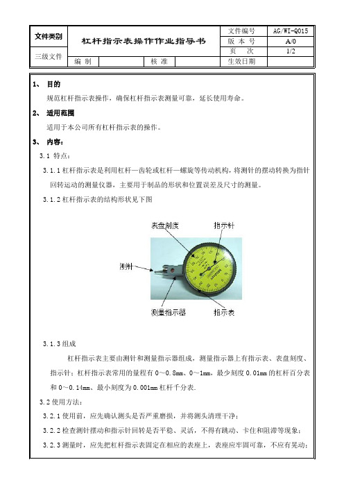
杠杆指示表主要由测针和测量指示器组成,测量指示器上有指示表、表盘刻度、指示针;杠杆指示表常用的量程有0~0.8mm、0~1mm,最少刻度0.01mm的杠杆百分表和0~0.14mm、最小刻度为0.001mm杠杆千分表.
3.2使用方法:
3.2.1使用前,应先确认测头是否严重磨损,并将测头清理干净;
4、注意事项:
4.1保持杠杆指示表清洁、防止碰撞,以免降低测量精度。
4.2当测头磨损时,应及时更换相应长度的测针,并进行确认精度是否有影响。
4.3使用时应尽量让杠杆指示表少接触油污,避免阳光照射,清洁杠杆ห้องสมุดไป่ตู้示表时,应用软布擦拭,以延长杠杆指示表的使用寿命和确保测量时的精度。
3.2.2检查测针摆动和指示针回转是否平稳、灵活,不得有跳动、卡住和阻滞等现象;
3.2.3测量时,应先把杠杆指示表固定在相应的表座上,表座应牢固可靠,不应有晃动;然后将测头缓慢的靠向被测制品的表面(尽量使被测面与测针垂直或平行),给测针施加一定的力度,让指示针适当的转动,接着转动表盘刻度,使指示针指向零位,最后根据测量的需要调整杠杆指示表或被测制品,并进行相应的读数。
1、目的
规范杠杆指示表操作,确保杠杆指示表测量可靠,延长使用寿命。
2、适用范围
适用于本公司所有杠杆指示表的操作。
3、内容:
3.1特点:
3.1.1杠杆指示表是利用杠杆—齿轮或杠杆—螺旋等传动机构,将测针的摆动转换为指针回转运动的测量仪器,主要用于制品的形状和位置误差及尺寸的测量。
3.1.2杠杆指示表的结构形状见下图
chrome DLX 杠杆式婴儿车舱面板说明书
Instruction Manualchrome ™DLXstrollerF IG U R E 29 - 34F IG U R E 41 - 4535 40F IG U R E 51 ~ 5646 5057 61NOTEGBContentsFigures 1-11 WARNING 15 Stroller Assembly18Open Stroller 18 Assemble Front Wheels 18 Assemble Rear Wheels 18 Assemble Armbar 18 Assemble Canopy 19 Stroller Operation 19 Use Canopy19 Switch Seat 19 Adjust Recline 19 Use Buckle 20 Use Shoulder & Waist Harnesses 20 Adjust Calf Support 21 Use Front Swivel Lock 21 Use Brake 21 Adjust Handle 21 Tether Strap 21 Fold Stroller 21 Use Shoulder Harness Pad Cover and Crotch Harness Pad Cover22Use Accessories 23 Care and Maintenance 26EmergencyIn case of emergency or accident, it is most important to have your child taken care of with first aid and medical treatment immediately.ARNINGFOLLOW THE MANUFACTURER’S INSTRUCTIONS.PUT ON ALL THE BRAKES WHENEVER YOU PARK THE PRAM/STROLLER.DO NOT LEAVE CHILDREN UNATTENDED.DO NOT CARRY EXTRA CHILDREN OR BAGS ON THIS PRAM/STROLLER.MAKE SURE CHILDREN ARE CLEAR OF ANY MOVING PARTS IF YOU ADJUST THE PRAM/STROLLER. OTHERWISE THEY MAY BE INJURED.ALWAYS KEEP CHILD IN VIEW WHILE IN PRAM/ STROLLER.DO NOT USE THE SEAT WITH ANY OTHER MODELS OF PRAM/STROLLER.SECURE THE CHILD IN THE HARNESS AT ALL TIMES. USE THIS HARNESS AT ALL TIMES.ALWAYS USE THE CROTCH COMBINATION WITH THE WAIST BELT. IT IS SUGGESTED THAT THE SHOULDER HARNESSES BE USED AS WELL.TO AVOID SERIOUS INJURY FROM FALLING OR SLIDING OUT, ALWAYS USE SEAT BELT.USE THIS TETHER STRAP TO STOP THE PRAM/ STROLLER ROLLING AWAY.DO NOT USE THIS BASSINET ONCE THE CHILD CAN SIT UP UNAIDED.DO NOT USE FOR UNSUPERVISED SLEEPING.Ensure that all the locking devices are engaged before use.Do not let your child play with this product.Never leave the harness buckled when not fitted to a child in the stroller because the harness can form loops which may pose a strangulation hazard.The use of accessories not approved by the vehicle manufacturer is unsafe.Adult assembly required.PLEASE TRANSPORT THE FOLDED STROLLER SAFEL e of this stroller with a child weighing more than 22 kg will cause excessive wear, and stress on the stroller, and could create an unstable condition. Use the stroller with only one child at a time.T o prevent a hazardous, unstable condition, do not place more than 4.5 kg in the storage basket before use. Overloading, folding incorrectly, or using component parts from other manufacturers may cause the pram/ stroller to be damaged﹐ broken or unsafe. Please read the instruction manual carefully.Please read all the instructions in the manual before using the product. Please save instruction manual for future use. Failure to follow these warnings and instructions may result in serious injury or death.Safety belts and restraint system must be used correctly. Child may slip into leg openings and be strangled if the harness is not used.Never use pram/stroller on stairs or escalators.The pram/stroller is not to be used near an open fire or exposed flame.Never allow your child to stand on the pram/stroller orsit in the pram/stroller with head toward front of pram/ stroller.Never place the pram/stroller on roads or dangerous area. The vehicle is designed for use on flat or gently sloping surfaces and may be unstable on higher sloping and uneven surfaces, resulting in the possibility of the vehicle tipping over.Do make sure all parts are assembled and fastened properly before using the pram/stroller.T o avoid strangulation, do not place items with a string around your child’s neck, suspend strings from this product, or attach strings to toys.T o prevent tipping, do not put anything on the handle. Always lift the child in and out of the pram/stroller.Do not lift pram/stroller while child is in stroller.Do not use storage basket as a child carrier.The rear-facing position is suitable for children under 2 years or less.T o prevent tipping, never let child climb the pram/stroller.T o avoid finger entrapment or injury to the body, use care when folding and unfolding the pram/stroller.Be sure the stroller is fully open or folded before allowing child near the pram/stroller.Check that the infant child restraint attachment device is correctly engaged before use.T o avoid strangulation, do make sure your child is clear from the canopy.Discontinue using your pram/stroller if it is damaged or broken.Pram/stroller to be used only at walking speed. This product is not intended for use while jogging.T o avoid suffocation, remove plastic bag and packaging materials before using this product. The plastic bag and packaging materials should then be kept away from babies and children.This product is not suitable for running or skating.Stroller designed to be used from birth shall recommend the use of the most reclined position for new born babies. The parking device must be engaged when placing and removing children.Bassinet is only suitable for a child who cannot sit up unaided, roll over and cannot push itself up on its hands and knees. Maximum weight of the child: 9kg.Bassinet is not to be used for long term sleeping.Do not use or add any mattress other than the one supplied with the bassinet.Please ensure that the storage latch has been properly locked, before lifting or moving the vehicle.The vehicle is not to be used as an unsupervised sleeping environment.The brakes must always be applied when the pram/stroller is not moving.For infant child restraint used in conjunction with a chassis, this vehicle does not replace a cot or a bed. Should your child need to sleep, then it should be placed in a suitable pram body, cot or bed.Stroller AssemblyPlease read all the instructions in this manual before assembling and using this product.Open StrollerSeparate storage latch from storage latch mount 1, and then lift the handle upwards 2, a click sound means the stroller is open completely. Press the recline handle on the back of backrest to rotate the backrest to vertical position. 3! Check that the stroller is completely open before continuing.Assemble Front WheelsAssemble front wheels to front legs. Check that wheels are securely attached by pulling on wheel assemblies. 4To disassemble front wheel, detach front wheel from front leg 5- 2 while pressing the release button. 5- 1Assemble Rear WheelsAssemble brake assembly to rear legs 6, assemble rear wheels to brake assembly 7. Pull the basket tube backward and wrap the connecting tube of rear legs with the flap of the storage basket, and then snap the three buttons 8- 1.! Check that wheels are securely attached by pulling on wheel assemblies. To disassemble rear wheel, detach rear wheel from rear wheel mount 7- 2 while pressing the release button. 7- 1Assemble ArmbarAlign the armbar ends with the armbar mounts, and then insert to lock. 9 To disassemble armbar, press armbar release button 10- 1, and then pull out the armbar. 10- 2Assemble CanopyTo assemble canopy, insert clips into mount 12, then attach 2 pairs of buttons. 11i. Engage the canopy webbing with recline buttons first. 11- 1ii. Then engage the softgood with canopy webbing and buttons. 11 - 2 The completely assembled stroller is shown as 13Stroller OperationUse CanopyOpen the zipper, then push the canopy forwards to open the canopy. 14 ! Please adjust the backrest to upright position before opening the canopy if it is convenient. 15! Please press the backrest before opening the canopy if it is not conve-nient to adjust the backrest to upright position. 16To fold the canopy, pull canopy toward back.! The canopy is NOT removable.Switch SeatThe seat can be switched, which makes mother and child can face to face with each.Squeeze the seat release buttons while lifting the seat. 17Turn the seat to reverse direction, and then insert the seat to seat mounts. 18Adjust ReclineThere are 5 positions for the backrest.To recline the backrest, squeeze the adjustment button 19- 1, and then adjust the backrest to a desired angle. 19- 2 To raise the backrest, push up.!Make sure the recline is set properly for e BuckleRelease BucklePress the center button to release the buckle. 20Lock BuckleMatch the waist belt buckle with the shoulder buckle 21- 1, and click into the center buckle. 21- 2 A “click” sound means the buckle is locked completely. 21- 3! To avoid serious injury from falling or sliding out, always secure your child with harness.! Make sure your child is snugly secured. The space between the child and the shoulder harness is about the thickness of one hand.! Do not cross the shoulder belts. This will cause pressure on child’s neck.Use Shoulder & Waist Harnesses! In order to protect your child from falling out, after your child is placed into the seat, check whether the shoulder and waist harnesses are at proper height and length.22- 1Shoulder harness anchor A22- 2Shoulder harness anchor B22- 3Slide adjusterFor larger child, use shoulder harness anchor A and the highest shoulder slots. For smaller child, use shoulder harness anchor B and the lowest shoulder slots.To adjust the position of the shoulder harness anchor, turn the anchor to be level with the side facing forward. Thread it through the shoulder harness slot from back to front. 23Rethread it through the slot that is closest to child's shoulder height. 24Use slide adjuster to change the harness length. 25- 1Press the button 25- 2, while pulling the waist harness to proper length. 25- 31920Press the recline handle on the back of backrest to rotate the backrest to horizontal position. 31Lift the folding button , step the folding pedal downwards, push the stroller forward to fold. 31The storage latch will automatically hook onto the storage mount, then the stroller is folded and locked completely. 32Use Shoulder Harness Pad Cover and Crotch Harness Pad CoverThe shoulder harness pad cover or crotch harness pad cover can be removed from the webbing. Simply reverse these steps to re-assemble shoulder harness and crotch harness pad cover.Use AccessoriesAccessories may be sold separately or may not be available depending on region.2122Adjust Calf SupportThe calf support has 2 positions.Raise Calf SupportTo raise the calf support, just push it upwards.Lower Calf SupportPress the adjustment buttons on both sides of the calf support 26 - 1, and rotate the calf support downwards. 26 - 2Use Front Swivel LockPush up the front swivel locks to maintain the moving direction. 27 It is recommended to use swivel locks on uneven surfaces.Use BrakeTo lock wheels, step the brake lever downwards. 28 To release wheels, just lift the brake lever upwards. 29 Always apply brake when stroller is in stopped position.Adjust HandleThe handle has 3 positions.To adjust the height of the handle, pull the handle upward or downward 30 - 2 while pressing the handle adjustment button. 30 - 1T ether StrapUse the tether strap to prevent the stroller inadvertently rolling away. Check that when your hand is through the loop, it allows you to easily control the stroller.Fold Stroller! Please fold the canopy before folding the stroller.Use with Joie Child RestraintWhen using with Joie child restraint gemm, i-Gemm please refer to the following instructions.1. To attach adapter, place adapter onto mounts as show 33, A “click”sound means the adapter is locked completely. 342. To attach child restraint, place child restraint onto adapter as show 35,A "click" sound means the child restraint is locked completely. 363. To remove child restraint, lift the child restraint upwards 37- 2 whilepressing the two stroller fix release buttons A. 37- 1!If you have any problems about using the stroller and the adapter, please refer to their own instruction manuals.!To remove adapter, lift the adapter upwards 38- 2 while pressing the two release buttons. 38- 1!Remove the adapter show as 39!Please don’t fold stroller when attaching the child restraint.Use BassinetYou can use this bassinet with the chrome DLX (S1201) stroller. Bassinet Assembly1. Please ensure the 2 support mounts are securely attached.4041! To release the support mounts, please see image 412. Please ensure that both attachment mounts, located on the sides, are securely attached. 4243! To release the attachment mounts, please see image 43- 23. Place the inner mattress and zip the zipper. 44454. Pull up the canopy as illustrated while pressing the buttons on bothsides. 46- 3Check to make sure the handle is secure before placing the child in the bassinet. 46- 1! Please make sure that the handle is in the correct position of usebefore carrying or lifting.5. Attach the loop and hook fasteners on the bottom of bassinet. 47A storage compartment is inside of the bassinet.47- 1! Always use the mattress when using the bassinet. 48! Mattress cover can easily be removed.6. Place the apron onto the top of the bassinet, and attach at the loopand fasteners. 49! Using the apron in cold weather will help give baby a more warm and comfortable environment.7. The completely assembled bassinet is shown as 50! To disassemble the bassinet simply reverse the steps above.8. Place the bassinet directly down until it latches into place. 519. The bassinet is securely attached with a positive “click”. 52! Always remove the seat before using the bassinet.! Please don’t fold the stroller when the bassinet is still attached.! The bassinet can be used with chrome DLX.10. Remove BassinetPress each release side button as shown 53- 1, whilst lifting up the handle simultaneously. 53- 211. Unzip the zipper to remove the canopy soft goods. 542324Use Footmuff ApronThe soft footmuff apron can provide your child with a warm and comfortable environment.Assemble the footmuff apron by following these steps.1. Adjust the calf support and backrest to level position and reclineposition respectively before assembling footmuff apron. 552. Cover the calf support with footmuff apron. 56The assembled footmuff apron is shown as 57.Use Rain CoverTo assemble the rain cover, place it over the stroller. 58!Before using the rain cover, to be make sure the seat has been fas-tened.!When using the rain cover, please always check its ventilation.!When not in use, please check that the rain cover has been cleaned and dried before folding.!Do not fold the stroller after assembling the rain cover.!Do not place your child into the stroller assembled with rain cover dur-ing hot weather.!To be used under adult supervision. Do not use on a stroller without a canopy.Use Seat Linersee images59Use Storage Bagsee images60The maximum load of Storage Bag is 0.45kg.Care and MaintenanceBassinet!Remove mattress from bassinet and mattress pad from liner. Clean liner and mattress with a damp cloth and dry flat.!CLEANING: After removing mattress pad from liner, hand wash,drip dry, NO BLEACH. Only use a damp cloth to clean the mattress pad. Never iron.!Removable seat pad may be washed in cold water and drip-dried. No bleach.!Excessive exposure to sun or heat could cause fading or warping of parts.Stroller!Removable seat pad may be washed in cold water and drip-dried. No bleach.!To clean stroller frame, use only household soap and warm water. No bleach or detergent.!From time to time, check your stroller for loose screws, worn parts,torn material or stitching. Replace or repair the parts as needed.!Excessive exposure to sun or heat could cause fading or warping of parts.!If stroller becomes wet, open hood and allow to dry thoroughly before storing.!If wheels squeak, use a light oil (e.g., Silicon Spray, antirust oil, or sewing machine oil). It is important to get the oil into the axle and wheel assembly. 61!When using your stroller at the beach, completely clean your stroller after use to remove sand and salt from mechanisms and wheel assemblies.2526Nuna Baby Australia Pty Ltd.Unit 1, 35 Lyn Parade Prestons,NSW Australia 2170Share the joy at joie IM-001147E。
福特竞速配件:高性能铝制杠杆臂指示书说明书

No cylinder head pedestal machining or additional components such as guide plates and rocker studs are required.
Engines with non-standard components, particularly performance camshafts, may need additional minimal machining or grinding of the pedestal inserts or different length push rods.
ALUMINUM ROLLER-TIP NEEDLE BEARING ROCKER ARMS STUD-MOUNTED TYPE AND BOLT-ON TYPE Instruction Sheet
NO PART OF THIS DOCUMENT MAY BE REPRODUCED WITHOUT PRIOR AGREEMENT AND WRITTEN PERMISSION OF FORD RACING PERFORMANCE PARTS.
TAPPET NOISE
Engines with standard components should run quietly without tappet noise. If engine operation was not noisy before installation of the rocker arms but is now, simple corrective action is necessary. See instructions below.
Factory Ford shop manuals are available from Helm Publications, 1-800-782-4356
嘉盛调整杠杆填表范本

嘉盛调整杠杆填表范本嘉盛调整杠杆填表范本随着经济全球化的加深与金融市场的日益发达,投资者们对于杠杆调整的需求也越来越迫切。
嘉盛作为一家知名的金融服务提供商,一直以来都在帮助客户实现财务目标。
在这篇文章中,我将为您详细介绍嘉盛调整杠杆的填表范本,并分享我对这个主题的个人观点和理解。
1. 背景和意义杠杆调整是指根据投资者的风险和回报需求,对投资组合进行重新配置,以达到投资目标的过程。
正确调整杠杆可以帮助投资者在风险可控的情况下实现更高的收益。
嘉盛提供的填表范本,旨在帮助投资者全面了解自身风险承受能力,并根据个人情况进行合理的杠杆调整。
2. 嘉盛调整杠杆填表范本的使用方法为了让您更好地理解和运用嘉盛调整杠杆填表范本,我将从以下几个方面进行详细说明:2.1 填表范本的基本使用方法嘉盛调整杠杆填表范本通常由几个主要部分组成:资产配置、持仓比例、风险偏好、风险因子等。
投资者可以根据自身情况填写这些表格,并根据填写结果进行杠杆调整。
2.2 资产配置的意义资产配置是指将资金分配到不同类型资产之间的过程。
在嘉盛调整杠杆填表范本中,投资者需要根据自己的投资目标和风险承受能力来确定资产配置比例。
对于风险承受能力较高的投资者,可以适度增加股票、期货等高风险资产的比例。
2.3 持仓比例的考虑因素持仓比例是指投资者在资产配置中各个资产类别的比例。
投资者在填写嘉盛调整杠杆填表范本时,需要根据自身情况进行持仓比例的评估。
对于投资者而言,应考虑到资产的流动性、风险收益特征等因素,合理分配不同资产类别的比例。
2.4 风险偏好的重要性风险偏好是指投资者在决策中对风险的态度和偏好。
填写嘉盛调整杠杆填表范本时,投资者需要清楚地了解自己对风险的容忍度和承受能力。
对于风险承受能力较低的投资者,应适度减少高风险资产的比例,以防止过于冒险的投资行为。
3. 个人观点和理解在我个人的观点和理解方面,嘉盛调整杠杆填表范本是一个非常实用的工具。
它能够帮助投资者全面了解自身的风险承受能力,并根据个人情况进行合理的杠杆调整。
- 1、下载文档前请自行甄别文档内容的完整性,平台不提供额外的编辑、内容补充、找答案等附加服务。
- 2、"仅部分预览"的文档,不可在线预览部分如存在完整性等问题,可反馈申请退款(可完整预览的文档不适用该条件!)。
- 3、如文档侵犯您的权益,请联系客服反馈,我们会尽快为您处理(人工客服工作时间:9:00-18:30)。
图 1-1.1
图 1-1.1 为零件实体图 2.零件工艺分析 通过对该零件的重新绘制,知道原图样的视图基本正确,完整尺寸,公差及技术要求 齐全。但下表面的精度较高。要进行精铣才能达到粗糙度要求。
该零件属于杆类零件,它的侧面都是直接锻造出来的,在加工时很方便,但要同 时保证孔的平行度和垂直度比较困难,但毛坯基本确定位置,所以简单了许多 3.零件的生产类型 依设计题目知:Q=2000 台/年,n=1 件/台;结合生产实际,备品率 α 和废品率 β 分 别取 10%和 1%。代入公式 N=Qn(1+α)(1+β)得该零件生产纲领
:50 45. 44. 43. by 42.41.— 4—0.— 3—9.—3—8.by37@.—— 36.35. —34—. ——33.312. 1.2.3.34.0.5.6—.—29.by28.by@27.26.—— 25. 24. 23. 22. by 21.20. — 1—9.by:18.by:17.— 1—6.— 1—5.—1—4.—— 13. 12. 111.0“. ”by: 9M.“OOOKN”b8y.:——7.——6.——5.——4.——3.——2.——1.——
参考资料以及说明: (1)崇凯.机械制造技术基础课程设计指南[M].北京:化学工业出版社,2010 (2)吕明.机械制造技术基础(第二版)[M].武汉:武汉理工大学出版社,2010 (3)陈宏钧.实用机械加工工艺手册[M].北京:机械工业出版社,2003 (4)符炜.实用切削加工手册[M].长沙:湖南科学技术出版社,2003
零件的工艺分析及生产类型确定 零件的作用
题目所给的零件是调速杠杆,主要作用是用于连接调速器,对侧面加工要求低, 对下孔的的加工精度要求比较高,尤其是 φ12mm 的孔有粗糙度的要求高,加工有困难。
:50 45. 44. 43. by 42.41.— 4—0.— 3—9.—3—8.by37@.—— 36.35. —34—. ——33.312. 1.2.3.34.0.5.6—.—29.by28.by@27.26.—— 25. 24. 23. 22. by 21.20. — 1—9.by:18.by:17.— 1—6.— 1—5.—1—4.—— 13. 12. 111.0“. ”by: 9M.“OOOKN”b8y.:——7.——6.——5.——4.——3.——2.——1.——
○2 锻件质量 m f
根据零件成品质量 0.25Kg ,估算为 m f
0.39Kg
。
○3 锻件形状复杂系数 S
S mf / mN
该锻件为非圆形锻件,长158.5mm ,宽 29mm ,假设最大厚度 53mm ,则由公式(5-
5)
mN lbhp 158.5 29 54 7.85 106 1.912Kg S m f / mN 0.39 /1.912 0.204
○5 零件的表面粗糙度 由于该零件图可知,该零件各加工表面为 Ra 1.6m 。
3.确定机械加工余量 根据锻件质量、零件表面粗糙度、形状复杂系数查表 5-9,由此查得单边余量在厚
2.机械制造技术基础课程设计指南》(崇凯 主编,李楠 副主编 2010 版)第五章
第一节,钢质模锻件的公差及机械加工余量按 GB/T 12362-2003 确定。要确定毛坯的
尺寸公差及机械加工余量,应先确定如下各项因素。 ○1 锻件公差等级 由该零件的功用和技术要求,确定其锻件公差等级为普通级。
N=2000 1 (1+10%) (1+1%)=2222 件/年
零件质量为 0.25kg,查表 2-1 得其属轻型零件,生产类型为中批生产。 选择毛坯及热处理、确定毛坯尺寸、设计毛坯图 选择毛坯 该零件的材料为 30 钢,考虑到零件的强度要求较高、形状比较简单,因此应该采用锻 件,以使金属纤维尽量不被切断,保证零件工作可靠。由于零件年产量为 2222 件,属 批量生产,而且零件的轮廓尺寸不大,故可采用模锻成型。这从提高生产率,保证加 工精度上考虑,也是应该的。
课程设计任务书 兹发给 2010 级机械 X 班 班学生 张 XX 课程设计任务书,内容如下:
设计题目: “135 调速器调速杠杆”零件机械加工工艺规程设计 应完成的项目: (1)原始资料:该零件图样,Q=2000 台/年,n=1 件/台,每日 1 班 (2)零件图 1 张,毛坯图 1 张; (3)机械加工工艺过程卡片 1 张; (4)机械加工工序卡片 1 套; (5)课程设计说明书 1 份。
本设计任务书于 2013 年 6 月 3 日发出,应于 2013 年 6 月 14 日前完成,然后进行答 辩。 目录
序言 机械制造技术基础课程设计是在学完了机械制造技术基础和大部分专业课,并进行了 生产实习的基础上进行的又一个实践性教学环节。这次设计使我们能综和运用机械制 造技术基础中的基本理论,并结合生产实习中学到的实践知识,独立的分析和解决了 零件机械制造工艺问题,设计了机床专用夹具这一典型的工艺装备,提高了结构设计 能力,为今后的毕业设计及未来从事的工作打下了良好的基础。 由于能力所限,经验不足,设计中还有很多不足之处,希望各位老师多加指教。
由于 0.204 介于 0.16 和 0.32 之间,故该零件的形状复杂系数 S 属于 S3 级。 ○4 锻件材质系数 M 由于该零件材料为 30 钢,是碳的质量分数小于 0.65% 的碳素钢, 故该锻件的材质系数属于 M 1 级
:50 45. 44. 43. by 42.41.— 4—0.— 3—9.—3—8.by37@.—— 36.35. —34—. ——33.312. 1.2.3.34.0.5.6—.—29.by28.by@27.26.—— 25. 24. 23. 22. by 21.20. — 1—9.by:18.by:17.— 1—6.— 1—5.—1—4.—— 13. 12. 111.0“. ”by: 9M.“OOOKN”b8y.:——7.——6.——5.——4.——3.——2.——1.——