DP4电流电压表说明书
DP4-PRDV20电压表说明书

11读数保持功能
12 数码管显示颜色:高亮红,蓝色,翠绿色,白色四种可选
3尺寸与接线端子图:
4 量程说明:
IN5135直流电压电流表常用量程: 允许输入满量程的120% 注:如一个直流20VDP4-PRDV20电压表只能测量20V之内电压,但不可以测电流。
满量程
分辨率
10mA
0.01Ω
提示 2510(5芯Байду номын сангаас子)仪表为直流5V供电,3.96(4芯端子)可以做直流5V 12V 24 V 交流9-12V 特殊工作电压可以定制
5 应用举例: 6 注意事项:
例:某电器标称额定工作电压为直流24V电流为8A我们采用数字表去监测电流电压值1选择IN5135-DC-200V IN5135-DC-10A/75mV各一只2辅助电源;DC5V/200mA稳压电源2个
输入电阻
量程扩展说明
±199.9mV
100uV
100MΩ(内阻)
1:表格列出量程可以直接信号接入测量,当电流大于5A以上需外接分流器来扩展量程,最大可配2000 A/75mV分流器来测量2000A之内的大电流. 特殊量程可以定制。例:如用户需要测量50A的直流电流,那么就需要50A/75mV分流器配合直流0-75mV显示0-50.0的数字表头来实现测量。2: 测量电压高于700V必须采用机外分压。例:如测量直流2000V高压,采用2000V/100V分压器分压配合直流0-100V输入显示0-1999的数字表来扩展测量。
2功耗≤60mA
3超量程千位显示1或-1后三位不显示
4 工作温度:-10~60℃ 湿度:85%以下
5显示字高0.56英寸
6测量速率约2.5次/秒 准确度:0.2%±2个字
DP4、DP4-EVF商品说明书
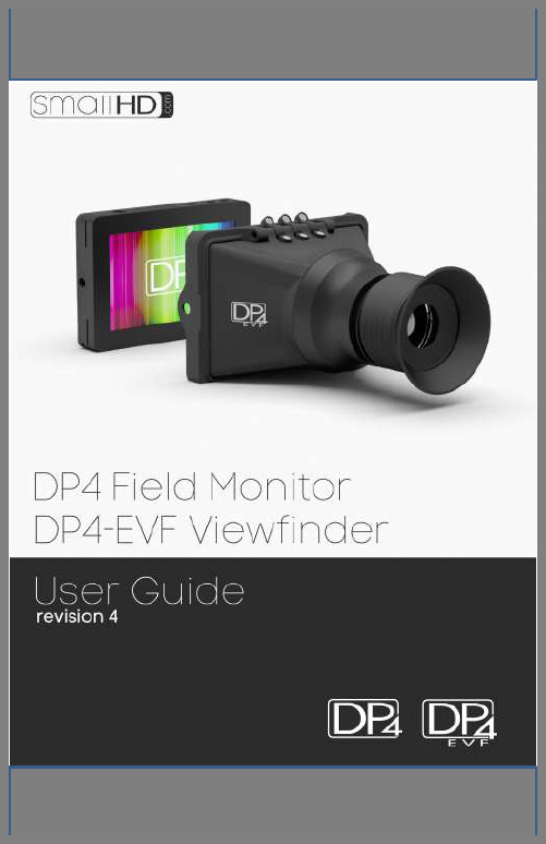
Table of ContentsProduct Introduction (3)Caring for your DP4 Monitor (4)Caring for your DP4-EVF Viewfinder (5)Positioning the Eyecup (5)What should be in the box: (6)DP4 Monitor: (6)VF Only: (6)DP4-EVF Combined: (6)DP4 Diagram (7)Powering the DP4: (8)The Power Switch (8)Battery Plates: (9)Powering with AC/DC Power: (11)The DP4-EVF: (12)Overview (12)Attaching the VF to the DP4 (13)Detaching the VF from the DP4: (14)Using the DP4-EVF (15)Using the DP4 (16)Operating the Menus (16)The Preset Menu: (17)DSLR Scale Presets (18)Assigning Function Buttons (19)Image Menu (20)Advanced Menu (21)False Color (22)1:1 Mapping (23)Input Menu (24)Changing inputs: (24)System Menu (25)Misc Menu (26)PIP Menu (26)Accessories (27)Attaching the Acrylic Screen Protector (27)Attaching the Sunhood (28)Updating Firmware (29)Specifications (30)Warranty (31)Thank You! (32)The DP4 The VF The DP4-EVF Product IntroductionOn Camera Field MonitorAn affordable, durable, 4.3-inch on-camera monitor packed full of inputs, outputs and professional software features. Extensive menu options plus a simple user interface, means quick and meaningful visual feedback when dialing in crucial details such as focus and exposure.Viewfinder Loupe Accessoryfor the DP4 MonitorAn optical loupe accessory designed to attach to the DP4 Field Monitor. This flip -up eyepiece adds the functionality of an EVF to the DP4, but does not remove its functionality as a monitor.Monitor/Viewfinder ComboThe Resulting combination the “DP4” and “VF” shownabove. The DP4-EVF operates seamlessly as either a4.3-inch monitor or as an EVF by simply flipping theeyepiece up or down and results by combining the“DP4 and “VF” shown above.Caring for your DP4 Monitor* The DP4’s DC input is CENTER PIN POSITIVE. Always check polarity of any custom cable implementations. SmallHD is not liable for any power related damage to your monitor due to incorrect polarity.* The DP4’s max input voltage is 18v DC. Over powering can result in damage to your DP4. SmallHD is not liable for any damage due to overpowering the unit.* Not all power sources are created equal. Using off-brand (non-Canon) LP-E6 batteries can result in undesired performance and longevity issues.* Do not attempt to disassemble the DP4. Doing so voids warranty.* If the DP4 is exposed to significant amounts of water, do not power on and contact SmallHD support. Water damage is not covered by warranty, but taking the right precautions when a water event occurs can sometimes preserve unit functionality.* Clean the screen with a high quality microfiber cloth only. Never spray the screen directly with any sort of cleaning fluid.* Always ask us if you have any questions about general operation. Contact SmallHD at /support*Much more information about the DP4 and other SmallHD products can be found online on our website and in video form at Caring for your DP4-EVF Viewfinder * Heed all instructions listed above regarding the DP4 Monitor* Do not expose the entrance of the EVF lens to direct sunlight. Doing so can magnify the sun and cause damage to the screen.* The aluminum lens assembly is air tight and sealed. Do not attempt to disassemble, as risk of contamination from dirt, dust and moisture can occur.* Clean the outside lenses as lightly as possible with a clean microfiber cloth only.Positioning the EyecupThe EVF Eyepiece is fixed to the assembly in a way that allows easy rotation and removal. The eyecup can also be positioned forward and back for optimal comfort.What should be in the box:DP4 Monitor:1.DP4 Field Monitor2.Sunhood3.Mini-HDMI Cable (1.5ft)4.YPbPr Breakout Cable (4ft)5.Hotshoe Ball Mount Power Supply7.Acrylic Screen Protector8.SmallHD Cleaning ClothVF Only:1.DP4 VF Adapter2.SmallHD Cleaning Cloth3.Circular Eyecup4.Lens CapDP4-EVF Combined:1.All of the aboveDP4 Diagram/ Composite OutPowering the DP4:The DP4 has two methods for powering:* Batteries, using the interchangeable battery plates* AC/DC Power, using the Barrel Power input on the back of the unit.The Power SwitchThe DP4 has a dual position power switch that distinguishes between using battery power, or the rear DC barrel power input. The switch has a depressed state (down) and a raised state (up). To use batteries, the switch should be DOWN. To use AC/DC Power via the barrel power input, the switch should be UP.Battery Plates:The DP4 comes standard with the dual battery plate of your choosing that is removable/replaceable with other types of plates. * Batteries can be used either in a single or double arrangement * Power switch should be depressed to activate battery power* Battery voltage can be read onscreen in the DP4 Menu System by activating “Voltage Meter” in the “System” Menu.Removing Battery Plates:The battery plates are not attached by screws, they just need the correct amount of force applied in the correct places to detach from the DP4 body. Some popping noises may occur during the battery plate removal process—this is normal and expected.Method 1:The recommended method is to insert a small flat-head screwdriver into the corner slot where the battery plate meets the metal body, then pull towards the rear of the DP4, lifting the corner of the plastic plate away from the metal DP4 housing.Method 2:Thread the ¼ 20 thread of the included ball mount into one of the two side ¼ 20 mounts a few times, then pull towards the rear using the body of the ball mount as leverage, while pushing the center of the back of the plate with your thumb.Replacing Battery Plates:Replacing battery plates is as simple as aligning the plate to the back of the DP4 and pressing in on the 4 corners. You should hear 4 audible “click” noises to confirm that it is completely attached.Powering with AC/DC Power:The DP4 has a barrel power input for powering from a wall using the included power supply, or from other sources such as Anton Bauer batteries.The specifications of this plug are below:**ALWAYS CHECK POLARITY BEFORE USING ANY POWER SOURCE THAT ISN’T THE INCLUDED POWER SUPPLY.The DP4-EVF:The DP4-EVF as a unit combines the DP4 Monitor (aka "DP4") and the DP4 Viewfinder Loupe Accessory (aka "VF"), which simply fixes to the front of the DP4 without the need for screws or adhesive. OverviewAttaching the VF to the DP4* Hold the VF with one hand and with the other, put one side of the DP4 in place, and then firmly press down on the other side to snap the VF in place.Detaching the VF from the DP4:Using your thumb, pull one of the side tabs of the VF back, then release the DP4 from that side—the other side will come out on its own once the first side is free.Using the DP4-EVF* The DP4-EVF incorporates magnets and a hinge to operate in two modes, closed and open. This makes it easy to quickly go from shooting mode to review mode, since you will not have to fiddle with latches or screws.* To adjust the eyepiece, simply rotate it to the most comfortable position.* The front of the lens assembly has standard 46mm threads for the use of diopters and UV filters. This will add thickness to the front and in some cases may protrude too far for comfort. This can be resolved by pulling the rubber eyecup back until it is flush around the very first element.Using the DP4Operating the Menus1 –Navigation Scroll Wheel* Click to activate Main Menu* Click to select items in menu* Scroll right and left to adjust values*(From no menu) Scroll any direction to access Preset menu2 –Back button/Preset A* Press to reverse out of the menu* Activate/deactivate Preset3 –Preset B Button* Activate/deactivate PresetActivating the menu and adjusting a function:1 – Click the scroll wheel one time2 – Roll the scroll wheel left or right to the proper sub menu3 – Click the wheel to select the sub menu4 – Roll the wheel to select the desired menu item5 – Click the wheel to select the desired menu item6 – Roll the wheel left or right to adjust the value7 – Press the back button to exit out of the menu systemVideo Tutorial:/Videos/dp4-user-interface-tutorial/DSLR Scale PresetsThe DSLR Scale presets are factory defined presets that enable the input signal from a variety of DSLR cameras to fill the screen of the DP4. Most monitors are unable to achieve this function. Special logic is in play when these presets are activated that keeps the image in full-screen mode even though the video signal may be changing aspect ratios behind the scenes (as in the case of the Canon 5D Mark 2, 60D, T2i, and T3i). As a result, the "Scale" and "CustomScale" menu functions are locked while using these presets.NOTE: Use preset "C DSLR REC" for Canon DSLR cameras during LiveView/Record mode. Use preset "N DSLR REC" for Nikon DSLR cameras during LiveView/Record mode. (*If using the Nikon D800 you can just use preset one on your monitor.) Use preset "PLAYBACK" when reviewing footage already recorded onto the Canon/Nikon DSLR.Assigning Function ButtonsThe DP4 has two buttons that can be assigned to custom functions for a convenient one press on/off of your favorite features.While not in any menus:1 – Press and hold either of the two buttons (A or B) for 3 secondsand release2 – Scroll with the scroll wheel to the desired function and clickthe scroll wheel to select it3 – Press the Back button to exit the menuImage MenuThe image menu controls Brightness, Contrast, Hue, Saturation, Sharpness and Gamma. Below is a description of each. Function Range DescriptionBrightness 0-100 Controls the maximum black point of the signal.Contrast 0-100 Controls the maximum white point of the signal.Hue 0-100 Also known as Tint or Phase.Saturation 0-100 Also known as Chroma.Sharpness 0-100 Amount of edge enhancement is applied.RGB Control 0-100 Adjusts RGB Gain and Offset for all 3 color channels.Gamma 2.2 Standard Gamma adjustment.Advanced MenuThe Advanced menu provides access to the many software tools of the DP4 to, among other things, aid in focus and exposure.Some of the functions are explained in greater detail in later pages, marked by the asterisk (*).Function Range DescriptionFocus Assist + On, Off Darkens image and outlines area in focus in white.False Color* HML, HL Overlays varying IRE levels in specific colors.Peaking On, Off Over-sharpens the image to give a frosted look to areas in focus.1:1 Mapping* On, Off Maps the native signal data to the screen of the DP4 –one native pixel to one DP4 screen pixel, no scaling.Scale 16:9, 4:3,2.35:1,1.85:1,AUTODefines the initial scalingparameters for the DP4.16:9, 4:3, etc.CustomScale 0-1000(x4) Stretch, shrink and move the image on screen pixel-by-pixel.Blue Only On, Off Turns the Red and Green color channels off. Used for calibrating to color bars.Monochrome On, Off Removes all color and leaves only the Luminance data of the signal.False ColorFalse color evaluates the incoming IRE levels (exposure) of the signal and then changes the colors of the pixels to represent what those IRE levels are. This is a quick way to gauge the exposure levels within an image in a very clear way.The DP4 currently has two different types of False Color.False Color HML (High / Mid / Low)Meaning High, Medium, Low, has colors for over-exposed, under-exposed and mid-range. The scale is below:BLUE PURPLE ORANGE GREEN YELLOW False Color HL (High / Low)Meaning High, Low, has colors for over and underexposed. The remaining middle will be monochrome.Image Flip H, V, HVFlip the image horizontally,vertically, or both.Freeze On, OffWhen activated will freezethe image on-screen. Turnoff to resume normal video.1:1 MappingWhen activated, each native pixel of the input signal is mapped to a native pixel on the display. This is also called “Pixel to Pixel”.When viewing HD signals (720p and up), only a portion of the image will be displayed on the DP4 as 1:1 Mapping essentially performs a "zooming" effect on the native HD image.To move the viewable window around:When 1:1 is activated and no menu is being displayed:1 – Roll the scroll wheel to the left2 – Now roll the wheel in either direction to move the window around3 – Press button B to change the direction of movement4 – Press the back button (Button A) to exit this dialogInput MenuThe DP4 has 3 inputs to choose from:1 – HDMI2 – YPbPr (SD/HD Component)3 – Composite (SD Only)Changing inputs:1 –Navigate to the “Input” sub menu with the scroll wheel2 – Scroll to the desired input3 – Click the scroll wheel onceSystem MenuThe System Menu provides access to critical system functions, listed below:Function Range DescriptionVolume 0-100 Controls the output volume to the headphone jackVoltage Meter On, Off Displays the current operating voltage, either from batteries or line power.USB Power Off, 5V Toggles power to the USB port, on or off.Factory Reset Reverts the DP4 back to factory defaultsDisplay On, Off Disables green input indicator text on top right of screenBacklight 0-10 Default set to 5, increase/decrease backlight brightnessMisc MenuThe Miscellaneous Menu simply contains options to change the menu background opacity level, and will display the current firmware version as a reference.PIP MenuThe DP4 allows two signals (1 HD and 1 SD) to be displayed simultaneously using the PIP or POP function, located in this menu.Function Range DescriptionMulti WindowPIP, POP (Full,4:3)Determines the typeof windowed view. SizeSmall, Medium,LargeDetermines the size ofthe window. Position TL, TR, BL, BRPosition of thewindow.Border Black, Blue Border or no border. Sub Source CompositeDetermines thesecondary source. Swap Swap Swaps the two signalsAccessoriesAttaching the Acrylic Screen ProtectorThe included acrylic screen protector is recommended as a precaution, but is not required. With the screen protector in place, the DP4 is much less vulnerable to damage.The screen protector is fixed to front of the DP4 using a temporary adhesive. To apply:1 – Remove the2 protective stickers from the front and back of the screen protector, then remove the 4 small white pieces from backside corners of the acrylic screen protector to expose the adhesive.2 – Carefully line up the screen protector using the top, bottom and side edges to the front of the DP4.3 – Place the screen protector on the front, and apply a small amount of pressure at the corners. It is not necessary to press hard; the adhesive will bond more on its own over time.Attaching the SunhoodThe DP4 Sunhood uses Velcro to fix to the front of the DP4. It works by looping through the two slots on the sides of the battery plate, and then reattaching to itself.Start by feeding one side of the Velcro strap into the slot, and then pulling it tight so the edge of the sunhood is flat against the surface of the front of the DP4. Then do the other side the same way. Keep pulling each side until the tension feels right, then fold the straps back and attach the Velcro.Updating FirmwareThe DP4 has the ability to upgrade its firmware based on new software developments. This is a unique ability of SmallHD monitors, and is very easy to do. To upgrade:1 – Format your USB thumb drive to FAT file system2 – Download the .BIN file from /support3 – Copy the .BIN file to your thumb drive4 – Insert the thumb drive into the included adapter cable and plug the mini-usb cable into the mini-usb port of the DP45 – Hold down the scroll wheel and then turn the DP4 on.6 – On screen instructions will inform when the process is complete.Video Tutorial/Videos/dp4-firmware-update-how-to-guide/WarrantyThe DP4 comes with a one year limited hardwarewarranty. The limited hardware warranty covers defects in materials and workmanship of our products.Warranty specifics:∙Warranty period begins on date of shipment∙Warranty is non-transferable; products not purchased directly from SmallHD or SmallHD approved affiliates anddistributors do not qualify for warranty coverage.∙The customer shall be responsible for paying shipping charges required to return products to SmallHD forwarranty repair. SmallHD shall pay for shipping ofrepaired products to the customer.What is not covered by our warranty:∙Problems resulting from accidents, abuse, or misuse∙Problems resulting from electrical power source issues∙3rd-party servicing not authorized by SmallHD∙Failure to follow product instructions∙Water damage∙Scratches to the body or panel that occur as part of normal useFor Dead Pixel Policy and other Warranty information, visit our website at /support。
交直流电流电压表说明书

准确度等级 功耗
10V ~ 30V:
0.45kΩ/V 1.5
40V ~ 500V:
0.9kΩ/V
电压降:
2.5
4-20mA: < 2V 其它
50mV ~ 0.5V
50uA ~ 800uA,25A ~ 60A
2.5
1mA ~ 20A,4-20mA 配外附分流器:75mV,60mV
电压降:
1.5
4-20mA:
1.5
1kΩ/V
6
交直流电流电压表
特征:1.KLY-50,560,60,670,780,80,8100 系列: ①透明盖:单色透明盖 T 或双色透明盖 S; ②后盖:翻式后盖 F 或紧固式后盖 J; ③安装螺钉:四脚或二脚。
2.KLY-01 系列:①双色透明盖;②安装螺钉:二脚。 3.KLY-02,03 系列:①双色透明盖;②安装螺钉:三脚。 4.KLY-04 系列:①双色透明盖;②安装螺钉:四脚。 5.KLY-801,1101 系列:①双色透明盖;②安装螺钉:四脚。
< 2V 其它
50mV ~ 0.5V
1.5
50uA ~ 800uA 1mA ~ 20A,4-20mA 配外附分流器:75mV,60mV
50mV ~ 300V
2.5
电压降:
1.5
4-20mA:
< 2V 其它 1.5 50mV ~ 0.5V
2.5
1kΩ/V
50mV ~ 500V
1.5
1kΩ/V
50mV ~ 500V
KLY-T144A
CP-T48V
10V ~ 500V
CP-T72V CP-T80V 90°电磁 CP-T96V
10V ~ 600V 配电压互感器:
DP4四位半智能电流电压表说明书

DP4四位半智能电流、电压、欧姆表使用说明书目录第一章概述-----------------------1 一概述-----------------------1二主要技术指标---------------2三型号说明-------------------3四外形及开口尺寸-------------7五端子接线-------------------8 第二章操作说明------------------9 一面板说明-------------------9二仪表的几种状态-------------11三操作说明-------------------111 上电自检-------------------112 参数设定-------------------122.1 参数设定概述----------------122.2 开锁------------------------162.3 报警------------------------162.4 小数点设定------------------172.5 调零------------------------172.6 输入量程设置----------------172.7 输入类型--------------------182.8 变送输出--------------------18 第三章功能说明---------------------19 一报警------------------------19二变送输出--------------------20第四章通讯协仪---------------------2 一通讯规程-----------------21二回答命令格式-------------21三数据形式-----------------21四通讯指令-----------------22五仪表参数代码-------------23第一章概述一概述4位半智能电流、电压、欧姆表采用当今最先进的ATMEL单片微机作主机,电流输入量程可任意设定,配合不同的互感器可满足各种测量量程的要求。
电压表操作说明书

电压表操作说明书操作说明书一、引言电压表是一种用来测量电路电压的仪器。
本操作说明书将介绍如何正确使用电压表进行测量和操作。
二、安全注意事项1. 在操作电压表之前,确保电路处于断开状态,并关闭电源。
2. 在操作过程中,确保双手干燥,防止触电事故发生。
3. 使用电压表前,务必仔细阅读说明书,并按照规范操作。
三、准备工作1. 将电压表置于稳定的台面上,并确保连接电源线插头牢固可靠。
2. 接通电源,待电压表显示正常后,即可开始操作。
四、电压测量1. 首先,选择合适的电压量程。
根据待测电压的大致范围,选择相应的量程档位。
2. 将电压表的红色测量笔连接到待测电路的正极,黑色测量笔连接到负极。
3. 确保测量笔与电路的接触良好,并避免导线短路,以免对电路产生干扰。
4. 在操作前,确认测量笔的接线正确,如有需要可以参考电路图。
5. 启动电压表,即可进行电压测量。
待电压表稳定后,记录测量结果。
五、注意事项1. 在进行电压测量时,要注意测量笔的极性,以免接反导致测量结果不准确。
2. 当测量直流电压时,选择正确的电压档位,以保证测量的准确性。
3. 在测量电压之前,确认待测电路已断电,并确认电路处于安全状态。
4. 使用电压表时,请勿将其暴露在潮湿或高温的环境中,以免影响仪器的稳定性。
六、故障排除1. 当电压表显示异常或读数不稳定时,首先检查电压表的电源和连接是否正常。
2. 如果问题仍然存在,可尝试重启电压表,并查看是否恢复正常。
3. 若仍未解决问题,可参考电压表的说明书进行故障排除,或者联系售后服务。
七、总结通过本操作说明书,我们了解了电压表的正确使用方法和注意事项。
在操作电压表时,务必保持谨慎,并按照规范进行操作,以确保安全和测量的准确性。
更多关于电压表的详细信息,请参考电压表的说明书以及相关技术资料。
谢谢您的使用!。
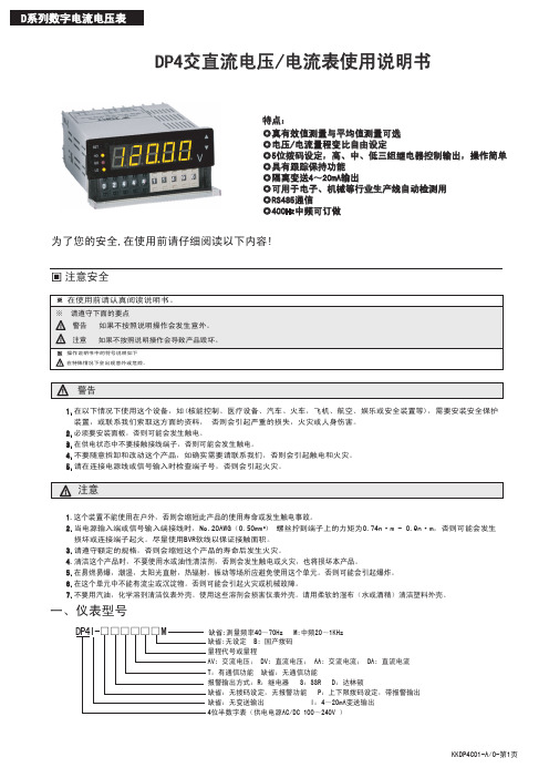
004 PZ 系列可编程智能电测表 ——三相电流、电压部分 (AI3、AV3) 安装使用说明书

004PZ系列可编程智能电测表——三相电流、电压部分(AI3、AV3)安装使用说明书V1.6安科瑞电气股份有限公司Acrel Co.,Ltd申明版权所有,未经本公司之书面许可,此手册中任何段落,章节内容均不得被摘抄、拷贝或以任何形式复制、传播,否则一切后果由违者自负。
本公司保留一切法律权利。
本公司保留对手册所描述之产品规格进行修改的权利,恕不另行通知。
订货前,请垂询当地代理商以获悉本产品的新规格。
目录1概述 (1)2产品型号规格 (1)3技术参数 (2)4安装指南 (2)4.1外形及安装尺寸 (2)4.2仪表及开孔示意图 (2)4.3安装示意图 (3)4.4安装说明 (3)4.5端子排列及接线 (3)4.6注意事项 (4)4.7典型应用 (6)5使用指南 (8)5.1按键 (8)5.2菜单符号及意义 (8)5.3编程流程 (8)5.4功能设置与使用 (10)6通讯指南 (11)6.1概述 (11)6.2协议 (12)6.3错误校验码的生成方法 (12)6.4三相表通讯参量地址表 (13)6.5通讯应用 (13)1概述PZ系列可编程智能三相电流、电压表,采用交流采样技术,可直接测量三相电网中的电流和电压。
既可用于本地显示,又能与工控设备连接,组成测控系统。
仪表可具有RS-485通讯接口,采用兼容Modbus-RTU协议;可将电量信号转换为标准的模拟量输出;或带一路继电器报警输出;或带四路(两路)开关量输入/两路开关量输出。
根据不同要求,通过仪表面板按键,对变比、报警、通讯等参数设置和控制。
2产品型号规格仪表型号基本功能外形可选功能PZ48-AI3 PZ48-AV3三相电流(或电压)测量LED数码管显示48方形无PZ48L-AI3 PZ48L-AV3三相电流(或电压)测量LCD液晶显示PZ72-AI3 PZ72-AV3三相电流(或电压)测量;LED数码管显示:72方形1、一路RS485通讯(/C)2、一路变送输出(/M)3、一路变送输出+一路RS485通讯(/MC)4、一路RS485通讯+开关量2DI2DO(/KC)PZ72L-AI3 PZ72L-AV3三相电流(或电压)测量;LCD液晶显示;PZ80-AI3 PZ80-AV3三相电流(或电压)测量;LED数码管显示:80方形1、一路RS485通讯(/C)2、最多三路变送输出(/M或/M3)3、变送输出+RS485通讯(/MC或/M3C)4、RS485通讯+开关量4DI2DO(/KC)PZ80L-AI3 PZ80L-AV3三相电流(或电压)测量;LCD液晶显示;PZ96-AI3 PZ96-AV3三相电流(或电压)测量;LED数码管显示:96方形1、一路RS485通讯(/C)2、最多三路变送输出(/M或/M3)3、变送输出+RS485通讯(/MC或/M3C)4、RS485通讯+开关量4DI2DO(/KC)PZ96L-AI3 PZ96L-AV3三相电流(或电压)测量;LCD液晶显示;注:/J为一路继电器报警输出(与第二路开关量输出复用),如有特殊需求请咨询本公司。
DP4交直流电电流表使用说明书(D版)
分辨力 1mV 10mV 100mV 1V 1V
输入阻抗 1.2M 12M 12M 12M 12M
互感器变比 直接输入 直接输入 直接输入 3KV/100V 10KV/100V
精度 ±0.1%F.S±3Digits ±0.1%F.S±3Digits ±0.2%F.S±3Digits ±0.2%F.S±3Digits ±0.2%F.S±3Digits
为了您的安全,在使用前请仔细阅读以下内容!
注意安全
在使用前请认真阅读说明书。 ※ 请遵守下面的要点
警告 如果不按照说明操作会发生意外。 注意 如果不按照说明操作会导致产品毁坏。
操作说明书中的符号说明如下 在特殊情况下会出现意外或危险。
警告
1.在以下情况下使用这个设备,如(核能控制、医疗设备、汽车、火车,飞机、航空、娱乐或安全装置等),需要安装安全保护 装置,或联系我们索取这方面的资料, 否则会引起严重的损失,火灾或人身伤害。
8:(48*96)
96
48
97.5
9
88.5
44.5
92
25
45
25
DP4电流/电压表使用Modbus RTU通信协议,进行RS485半双工通信,读功能号0x03,写功能号0x10,采用16位CRC校验,仪表对校验 错误不返回。
数据帧格式:
起止位 数据位 停止位 校验位
1
8
1
无
通信异常处理:
异常应答时,将功能号的最高位置1。例如:主机请求功能号是0x04,则从机返回的功能号对应项为0x84。 错误类型码: 0x01┄功能码非法:仪表不支持接收到的功能号。 0x02┄数据位置非法:主机指定的数据位置超出仪表的范围。 0X03┄数据值非法:主机发送的数据值超出仪表对应的数据范围。 CRC校验码错不返回数据。
4位高端蓝光显示直流电压表说明书
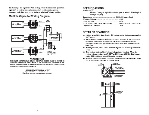
2. Connect the ground cable witrefer to the attached drawing.
3. Place the supplied charging bulb between positive terminal of the capacitor and the battery's positive terminal. Do this for 2 ~ 3 minutes or until the charging bulb goes out.
DISCHARGING THE CAPACITOR:
When you want to take out the capacitor after you finish the installation process from original car audio system. You must do discharge process when you want to move the capacitor. It will be safe to release the power of the capacitor.
- 1、下载文档前请自行甄别文档内容的完整性,平台不提供额外的编辑、内容补充、找答案等附加服务。
- 2、"仅部分预览"的文档,不可在线预览部分如存在完整性等问题,可反馈申请退款(可完整预览的文档不适用该条件!)。
- 3、如文档侵犯您的权益,请联系客服反馈,我们会尽快为您处理(人工客服工作时间:9:00-18:30)。
001.DP4电流电压表欧姆表使用说明书V1.0
2.1、主要特点
✧友好的人机界面,易学易用,操作快捷。
✧采用开关电源适应85V-240VAC范围或者24VDC电源供电。
✧模块化结构,灵活配置,方便升级。
✧采用贴片技术(SMT),设计更加简洁、轻巧。
✧支持多种输入类型,现场配置灵活方便。
✧热电偶、热电阻输入采用非线性修正,测量精度高,稳定性好。
2.2、技术指标
●输入规格:
交流电压,交流电流.
直流电压,直流电流
扩充规格:在保留上述输入规格基础上,允许用户指定一种额外输入规格(非线性输入可能需要提供分度表)
●测量精度:0.2级
●响应时间:≤0.5秒(设置数字滤波参数FiL=0时)
●输出规格(模块化):
继电器触点开关输出:220VAC/3A、220VAC/0.8A
可控硅无触点开关输出:100-240VAC/0.2A(持续),2A(20mS瞬时,重复周期大于5S)
SSR电压输出:12VDC/30mA (用于驱动SSR固态继电器)
可控硅触发输出:可触发5-500A的双向可控硅、2个单向可控硅反并联连接或可控硅功率模块
线性电流输出:0-10mA或4-20mA 可定义
●报警功能:上限、上上限、下限、下下限、正偏差、负偏差等6种方式,最多可输出3路
●电源:85-240VAC,-15%,+10% / 50-60Hz;或24VDC/AC,-15%,+10%
●电源消耗:≤5W
●环境温度:0-50℃
●环境湿度:<85%RH
2.3、型号定义
仪表的型号定义如下:
一:型号及含义
DP 4—□□—□变送:缺省:无;V1:0-5V;V2:1-5V;A1:0-20mA;A2:4-20mA
量程代号
DV:直流电压;DA:直流电流;A V:交流电压;AA:交流电流R 欧姆表
电流电压表欧姆表
2.4、模块说明
R1A 继电器常开(压敏电阻吸收)输出模块(容量:30VDC/0.8A ,220VAC/0.8A )
R1B 继电器常闭触点开关(压敏电阻吸收)输出模块(容量:30VDC/0.8A ,220VAC/0.8A ) R1C 继电器常开+常闭触点开关(压敏电阻吸收)输出模块(容量:30VDC/0.8A ,220VAC/0.8A ) R2A 大容量继电器常开触点开关(阻容吸收)输出模块(容量:30VDC/3A ,220VAC/3A ) R2B 大容量继电器常闭触点开关(阻容吸收)输出模块(容量:30VDC/3A ,220VAC/3A ) R2C 大容量继电器常开+常闭触点开关(阻容吸收)输出模块(容量:30VDC/3A ,220VAC/3A ) W 1可控硅无触点输出模块(容量:100-240VAC/0.2A ) G 固态继电器驱动电压输出模块(DC 12V/50mA 输出)
K1单路可控硅过零触发输出模块(每路可触发5-500A 双向或二个反并联的单向可控硅) K2双路可控硅过零触发输出模块(每路可触发5-500A 双向或二个反并联的单向可控硅) I1光电隔离的可编程线性电流输出模块 S1 光电隔离RS485通讯接口模块 S2 光电隔离RS232通讯接口模块
U1/U2/U3 隔离的5V/12V/24V 直流电压输出,可供外部变送器等传感器或其它电路使用,最大电流50mA
例1、
有一台仪表的型号是:DP4-AA500-R1C-R1A-I1-N-N-AC ,则它的配置如下:
主机型号:DP4-AA500,交流500V 电流表 面板尺寸:96×96 mm
报警输出:继电器常开+常闭触点开关输出模块 辅助输出1:继电器常开输出模块
辅助输出2:光电隔离的可编程线性电流输出模块 辅助输出3:无 输入:温度 电源:85-240VAC
辅助输出2:光电隔离的可编程线性电流输出模块 辅助输出3:无 输入:温度 电源:85-240VAC
主机型号:DP4-AA500,交流500V 电流表
面板尺寸:96×96 mm
报警输出:继电器常开+常闭触点开关输出模块
辅助输出1:继电器常开输出模块
说明:
1:测量精度测试环境条件为:温度20±2℃相对湿度45-75%。
2:表中所列量程为常规量程。
其它特殊量程可按用户要求定制。
七:接线图
说明:
1:输入信号为直流时“+”端接信号正极,“-”端接信号负极,输入信号为交流时“+”端接信号的火线或高端,“-”端接信号的零线或低端。
2:接线如有变动,以出厂仪表配备接线图为准。