注塑成型模具设计工具中英文对照外文翻译文献
塑料模具发展中英文对照外文翻译文献

中英文对照外文翻译文献(文档含英文原文和中文翻译)外文:The development of plastic mouldChina's industrial plastic moulds from the start to now, after more than half a century, there has been great development, mold levels have been greatly enhanced. Mould has been at large can produce 48-inchbig-screen color TV Molded Case injection mold, 6.5 kg capacity washing machine full of plastic molds, as well as the overall car bumpers and dashboards, and other plastic mould precision plastic molds, the camera is capable of producing plastic mould , multi-cavity mold small modulus gear and molding mold. --Such as Tianjin and Yantai daysElectrical Co., Ltd Polaris IK Co. manufactured multi-cavity mold VCD and DVD gear, the gear production of such size precision plastic parts, coaxial, beating requirements have reached a similar foreign the level of product, but also the application of the latest gear design software to correct contraction as a result of the molding profile error to the standard involute requirements. Production can only 0.08 mm thickness of atwo-cavity mold and the air Cup difficulty of plastic doors and windows out of high modulus, and so on. Model cavity injection molding manufacturing accuracy of 0.02 to 0.05 mm, surface roughness Ra0.2 μ m, mold quality, and significantly increase life expectancy,non-hardening steel mould life up to 10~ 30 million, hardening steel form up to 50 ~ 10 million times, shorten the delivery time than before, but still higher than abroad,and the gap between a specific data table.Process, the multi-material plastic molding die, efficient multicolor injection mould, inserts exchange structure and core pulling Stripping the innovative design has also made great progress. Gas-assisted injection molding, the use of more mature technologies, such as Qingdao Hisense Co., Ltd., Tianjin factorycommunications and broadcasting companies, such as moldmanufacturers succeeded in 29 ~ 34-inch TV thick-walled shell, as well as some parts on the use of gas-assisted mould technology Some manufacturers also use the C-MOLD gas-assisted software and achieved better results. Prescott, such as Shanghai, such as the newcompany will provide users with gas-assisted molding equipment and technology. Began promoting hot runner mold, and some plants use rate of more than 20 percent, the general heat-thermal hot runner, or device, a small number of units with the world's advanced level of rigorous hot runner-needle device, a small number of units with World advanced level of rigorous needle-hot runner mould. However, the use of hot runner overall rate of less than 10%, with overseas compared to 50 ~ 80%, the gap larger. In the manufacturing technology, CAD / CAM / CAE technology on the level of application of a new level to the enterprise for the production of household appliances representatives have introduced a considerable number of CAD / CAM systems, such as the United States EDS UG Ⅱ, the United States Parametric Technology Pro / Engineer, the United States CV CADS5 company, the British company DOCT5 Deltacam, HZS's CRADE Japan, the company's Cimatron Israel, the United States AC-C-Tech Mold Company and Australia's MPA Mold flow Mold analysis software, and so on. These systems and the introduction of the software, although a lot of money spent, but in our country die industry, and achieving a CAD / CAM integration, and to support CAE technology to forming processes such as molding and cooling, such as computer simulation, and achieved certain The technical and economic benefits, promote and facilitate China's CAD / CAM technology. In recent years, China's own development of the plasticmould CAD / CAM system has achieved significant development, the main guarantor Software Engineering Institute, is the development of CAXA, Huazhong University of Science HSC5.0 development of the system and injection mold CAE software, and so on, these Die of domestic software with the specific circumstances in the application of computer and lower prices, and other characteristics, in order to further universal CAD / CAM technology has created good conditions.In recent years, China has been more extensive use of some new plastic mold steel, such as: P20, 3Cr2Mo, PMS, SM Ⅰ, SM Ⅱ, and the quality of life of mold has a direct significant impact on the overall use of the still less . Plastic Moulds standard model planes, such as standard putter and spring has given more applications, and there have been some of the commercialization of domestic hot runner system components. However, at present China Die level of standardization and commercialization in the general level of below 30 percent and foreign advanced industrial countries has reached 70 percent compared to 80 percent, still a large gap. Table 1, at home and abroad plastic mould technology comparison table? Domestic projects abroad cavity injection model mm0.02 accuracy of 0.005 ~ 0.01 ~ 0.05mm cavity surface roughness Ra0.01 ~ 0.05 μ mRa0.20 μ m non-hardened steel die life 10 to 60 million 10 ~ 30 million hardened steel die life 160 ~ 300 million of 50 ~ 100 million hot runner mould overall utilization rate of more than 80per cent less than 10 per cent level of standardization of 70 ~ 80% less than 30% of medium-sized plastic mould production cycle about a month 2 ~ 4 months in the mold industry in the amount of 30 to 40% 25 to 30% According to the parties concerned forecast, the market's overall vigorous mold is a smooth upward, in the next Die market, the development of plastic mould faster than the other Die, die in the proportion of industry will gradually improve. With the continuous development of the plastics industry, put on the plastic mold growing demands is a normal, and so sophisticated, large-scale, complex, long-life plastic mould development will be higher than the overall pace of development. At the same time, imports in recent years because of the mold, precision, large, complex, long-life die in the majority, therefore, reduce imports, increase Guochanhualu: perspective, in the mold of such high-end market share will gradually increase. The rapid development of theconstruction industry so that the various Profile Extrusion Die, PVC plastic pipe fittings Die Die market become a new economic growth point, the rapid development of highways, car tires also put a higher demand, radial tire Die, Die particularly active pace of development will also be higher than the overall average level of the plastic and wood, plastic and metal to make plastic molds in the automotive, motorcycle industry in the demand for huge household appliances industry in the "10th Five-Year Plan" period have greater development, especially refrigerators,air-conditionersand microwave ovens, and other parts of the great demand for plastic moulds, and electronics and communications products, in addition to audio-video products, such as color televisions, laptop computers and set-top boxes will be given a wider network development, which are Plastic Mold market is the growth point. Second, China's industrial and technological plastic mould the future direction of the major developments will include:1, raising large, sophisticated, complex, long-life mold design and manufacturing standards and proportion. This is due to the molding plastic mould products increasingly large, complex and high-precision requirements, as well as requirements for high productivity and the development of a multi-mode due.2, in the design and manufacture of plastic mould fully promote the use of CAD / CAM / CAE technology. CAD / CAM technology has developed into a relatively mature technology common in recent years CAD / CAM technology hardware and software prices has been reduced to SMEs generally acceptable level of popularity for further create good conditions; based on network CAD / CAM / CAE system integration structure the initial signs of emerging, and it will solve the traditional mixed CAD / CAM system can not meet the actual production process requirements of the division of collaboration; CAD / CAM software will gradually improve intelligence plastic parts and the 3-D mold design andprototyping process 3-D analysis will be in our plastic mould industries play an increasingly important role.3, promote the use of hot runner technology, gas-assisted injection molding technology and high-pressure injection molding technology. Using hot runner mould technology can improve the productivity and quality of parts and plastic parts can be substantial savings of raw materials and energy conservation, extensive application of this technology is a big plastic mould changes. Hot Runner components formulate national standards, and actively produce cheap high-quality components, the development of hot runner mold is the key. Gas-assisted injection molding product quality can be guaranteed under the premise of substantially lower cost. Currently in the automotive and appliance industries gradually promote the use of the Chiang Kai-shek. Gas-assisted injection molding of the ordinary than the traditional injection of more parameters need to identify and control, and its more commonly used in large, complex products, mold design and control more difficult, therefore, the development of gas-assisted molding flow analysis software It seems very important. On the other hand in order to ensure precision plastic parts to continue to study the development of technology and high-pressure injection molding and injection-compression molding mould and die technology is also very important.4, the development of new plastics molding technology and rapid economic mold. To adapt to more variety, less volume of production.5, and improve standardization of plastic mould standard parts usage. China's mold and die level of standard parts standardization still low, the gap between the large and foreign, to a certain extent constraining the development of industries in our country die, die to improve quality and reduce manufacturing costs Die, Die standard parts to vigorously promote the application. To this end, first of all, to formulate a unified national standards, and in strict accordance with the standards of production, secondly it is necessary to gradually scale production, to improve the commercialization of the standard of quality, and reduce costs; again it is necessary to further increase the standard specifications of varieties.6, Die application quality materials and advanced surface treatment technology for improving the quality of life and mold it is necessary.7, research and application of high-speed die measurement technology and reverse engineering. CMM-use 3D scanner or reverse engineering is the realization of plastic moulds CAD / CAM one of the key technologies.Research and Application of diversity, adjustment, cheap detection equipment is to achieve the necessary precondition for reverse engineering.译文:塑料模具的发展我国塑料模工业从起步到现在,历经半个多世纪,有了很大发展,模具水平有了较大提高。
塑料注塑模具中英文对照外文翻译文献
外文翻译及原文(文档含英文原文和中文翻译)【原文一】CONCURRENT DESIGN OF PLASTICS INJECTION MOULDS AbstractThe plastic product manufacturing industry has been growing rapidly in recent years. One of the most popular processes for making plastic parts is injection moulding. The design of injection mould is critically important to product quality and efficient product processing.Mould-making companies, who wish to maintain the competitive edge, desire to shorten both design and manufacturing leading times of the by applying a systematic mould design process. The mould industry is an important support industry during the product development process, serving as an important link between the product designer and manufacturer. Product development has changed from the traditional serial process of design, followed by manufacture, to a more organized concurrent process where design and manufacture are considered at a very early stage of design. The concept of concurrent engineering (CE) is no longer new and yet it is still applicable and relevant in today’s manuf acturing environment. Team working spirit, management involvement, total design process and integration of IT tools are still the essence of CE. The application of The CE process to the design of an injection process involves the simultaneous consideration of plastic part design, mould design and injection moulding machine selection, production scheduling and cost as early as possible in the design stage.This paper presents the basic structure of an injection mould design. The basis of this system arises from an analysis of the injection mould design process for mould design companies. This injection mould design system covers both the mould design process and mould knowledge management. Finally the principle of concurrent engineering process is outlined and then its principle is applied to the design of a plastic injection mould.Keywords :Plastic injection mould design, Concurrent engineering, Computer aided engineering, Moulding conditions, Plastic injection moulding, Flow simulation1.IntroductionInjection moulds are always expensive to make, unfortunately without a mould it can not be possible ho have a moulded product. Every mould maker has his/her own approach to design a mould and there are many different ways of designing and building a mould. Surely one of the most critical parameters to be considered in the design stage of the mould is the number of cavities, methods of injection, types of runners, methods of gating, methods of ejection, capacity and features of the injection moulding machines. Mould cost, mould quality and cost of mould product are inseparableIn today’s completive environment, computer aided mould filling simulation packages can accurately predict the fill patterns of any part. This allows for quick simulations of gate placements and helps finding the optimal location. Engineers can perform moulding trials on the computer before the part design is completed. Process engineers can systematically predict a design and process window, and can obtain information about the cumulative effect of the process variables that influence part performance, cost, and appearance.2.Injection MouldingInjection moulding is one of the most effective ways to bring out the best in plastics. It is universally used to make complex, finished parts, often in a single step, economically, precisely and with little waste. Mass production of plastic parts mostly utilizes moulds. The manufacturing process and involving moulds must be designed after passing through the appearance evaluation and the structure optimization of the product design. Designers face a hugenumber of options when they create injection-moulded components. Concurrent engineering requires an engineer to consider the manufacturing process of the designed product in the development phase. A good design of the product is unable to go to the market if its manufacturing process is impossible or too expensive. Integration of process simulation, rapid prototyping and manufacturing can reduce the risk associated with moving from CAD to CAM and further enhance the validity of the product development.3. Importance of Computer Aided Injection Mould DesignThe injection moulding design task can be highly complex. Computer Aided Engineering (CAE) analysis tools provide enormous advantages of enabling design engineers to consider virtually and part, mould and injection parameters without the real use of any manufacturing and time. The possibility of trying alternative designs or concepts on the computer screen gives the engineers the opportunity to eliminate potential problems before beginning the real production. Moreover, in virtual environment, designers can quickly and easily asses the sensitivity of specific moulding parameters on the quality and manufacturability of the final product. All theseCAE tools enable all these analysis to be completed in a meter of days or even hours, rather than weeks or months needed for the real experimental trial and error cycles. As CAE is used in the early design of part, mould and moulding parameters, the cost savings are substantial not only because of best functioning part and time savings but also the shortens the time needed to launch the product to the market.The need to meet set tolerances of plastic part ties in to all aspects of the moulding process, including part size and shape, resin chemical structure, the fillers used, mould cavity layout, gating, mould cooling and the release mechanisms used. Given this complexity, designers often use computer design tools, such as finite element analysis (FEA) and mould filling analysis (MFA), to reduce development time and cost. FEA determines strain, stress and deflection in a part by dividing the structure into small elements where these parameters can be well defined. MFA evaluates gate position and size to optimize resin flow. It also defines placement of weld lines, areas of excessive stress, and how wall and rib thickness affect flow. Other finite element design tools include mould cooling analysis for temperature distribution, and cycle time and shrinkage analysis for dimensional control and prediction of frozen stress and warpage.The CAE analysis of compression moulded parts is shown in Figure 1. The analysis cycle starts with the creation of a CAD model and a finite element mesh of the mould cavity. After the injection conditions are specified, mould filling, fiber orientation, curing and thermal history, shrinkage and warpage can be simulated. The material properties calculated by the simulation can be used to model the structural behaviour of the part. If required, part design, gate location and processing conditions can be modified in the computer until an acceptable part is obtained. After the analysis is finished an optimized part can be produced with reduced weldline (known also knitline), optimized strength, controlled temperatures and curing, minimized shrinkage and warpage.Machining of the moulds was formerly done manually, with a toolmaker checking each cut. This process became more automated with the growth and widespread use of computer numerically controlled or CNC machining centres. Setup time has also been significantly reduced through the use of special software capable of generating cutter paths directly from a CAD data file. Spindle speeds as high as 100,000 rpm provide further advances in high speed machining. Cutting materials have demonstrated phenomenal performance without the use of any cutting/coolant fluid whatsoever. As a result, the process of machining complex cores and cavities has been accelerated. It is good news that the time it takes to generate a mould is constantly being reduced. The bad news, on the other hand, is that even with all these advances, designing and manufacturing of the mould can still take a long time and can be extremely expensive.Figure 1 CAE analysis of injection moulded partsMany company executives now realize how vital it is to deploy new products to market rapidly. New products are the key to corporate prosperity. They drive corporate revenues, market shares, bottom lines and share prices. A company able to launch good quality products with reasonable prices ahead of their competition not only realizes 100% of the market before rival products arrive but also tends to maintain a dominant position for a few years even after competitive products have finally been announced (Smith, 1991). For most products, these two advantages are dramatic. Rapid product development is now a key aspect of competitive success. Figure 2 shows that only 3–7% of the product mix from the average industrial or electronics company is less than 5 years old. For companies in the top quartile, the number increases to 15–25%. For world-class firms, it is 60–80% (Thompson, 1996). The best companies continuously develop new products. AtHewlett-Packard, over 80% of the profits result from products less than 2 years old! (Neel, 1997)Figure 2. Importance of new product (Jacobs, 2000)With the advances in computer technology and artificial intelligence, efforts have been directed to reduce the cost and lead time in the design and manufacture of an injection mould. Injection mould design has been the main area of interest since it is a complex process involving several sub-designs related to various components of the mould, each requiring expert knowledge and experience. Lee et. al. (1997) proposed a systematic methodology and knowledge base for injection mould design in a concurrent engineering environment.4.Concurrent Engineering in Mould DesignConcurrent Engineering (CE) is a systematic approach to integrated product development process. It represents team values of co-operation, trust and sharing in such a manner that decision making is by consensus, involving all per spectives in parallel, from the very beginning of the productlife-cycle (Evans, 1998). Essentially, CE provides a collaborative, co-operative, collective and simultaneous engineering working environment. A concurrent engineering approach is based on five key elements:1. process2. multidisciplinary team3. integrated design model4. facility5. software infrastructureFigure 3 Methodologies in plastic injection mould design, a) Serial engineering b) Concurrent engineeringIn the plastics and mould industry, CE is very important due to the high cost tooling and long lead times. Typically, CE is utilized by manufacturing prototype tooling early in the design phase to analyze and adjust the design. Production tooling is manufactured as the final step. The manufacturing process and involving moulds must be designed after passing through the appearance evaluation and the structure optimization of the product design. CE requires an engineer to consider the manufacturing process of the designed product in the development phase.A good design of the product is unable to go to the market if its manufacturing process is impossible. Integration of process simulation and rapid prototyping and manufacturing can reduce the risk associated with moving from CAD to CAM and further enhance the validity of the product development.For years, designers have been restricted in what they can produce as they generally have todesign for manufacture (DFM) – that is, adjust their design intent to enable the component (or assembly) to be manufactured using a particular process or processes. In addition, if a mould is used to produce an item, there are therefore automatically inherent restrictions to the design imposed at the very beginning. Taking injection moulding as an example, in order to process a component successfully, at a minimum, the following design elements need to be taken into account:1. . geometry;. draft angles,. Non re-entrants shapes,. near constant wall thickness,. complexity,. split line location, and. surface finish,2. material choice;3. rationalisation of components (reducing assemblies);4. cost.In injection moulding, the manufacture of the mould to produce the injection-moulded components is usually the longest part of the product development process. When utilising rapid modelling, the CAD takes the longer time and therefore becomes the bottleneck.The process design and injection moulding of plastics involves rather complicated and time consuming activities including part design, mould design, injection moulding machine selection, production scheduling, tooling and cost estimation. Traditionally all these activities are done by part designers and mould making personnel in a sequential manner after completing injection moulded plastic part design. Obviously these sequential stages could lead to long product development time. However with the implementation of concurrent engineering process in the all parameters effecting product design, mould design, machine selection, production scheduling,tooling and processing cost are considered as early as possible in the design of the plastic part. When used effectively, CAE methods provide enormous cost and time savings for the part design and manufacturing. These tools allow engineers to virtually test how the part will be processed and how it performs during its normal operating life. The material supplier, designer, moulder and manufacturer should apply these tools concurrently early in the design stage of the plastic parts in order to exploit the cost benefit of CAE. CAE makes it possible to replace traditional, sequential decision-making procedures with a concurrent design process, in which all parties can interact and share information, Figure 3. For plastic injection moulding, CAE and related design data provide an integrated environment that facilitates concurrent engineering for the design and manufacture of the part and mould, as well as material selection and simulation of optimal process control parameters.Qualitative expense comparison associated with the part design changes is shown in Figure 4 , showing the fact that when design changes are done at an early stages on the computer screen, the cost associated with is an order of 10.000 times lower than that if the part is in production. These modifications in plastic parts could arise fr om mould modifications, such as gate location, thickness changes, production delays, quality costs, machine setup times, or design change in plastic parts.Figure 4 Cost of design changes during part product development cycle (Rios et.al, 2001)At the early design stage, part designers and moulders have to finalise part design based on their experiences with similar parts. However as the parts become more complex, it gets rather difficult to predict processing and part performance without the use of CAE tools. Thus for even relatively complex parts, the use of CAE tools to prevent the late and expensive design changesand problems that can arise during and after injection. For the successful implementation of concurrent engineering, there must be buy-in from everyone involved.5.Case StudyFigure 5 shows the initial CAD design of plastics part used for the sprinkler irrigation hydrant leg. One of the essential features of the part is that the part has to remain flat after injection; any warping during the injection causes operating problems.Another important feature the plastic part has to have is a high bending stiffness. A number of feeders in different orientation were added to the part as shown in Figure 5b. These feeders should be designed in a way that it has to contribute the weight of the part as minimum aspossible.Before the design of the mould, the flow analysis of the plastic part was carried out with Moldflow software to enable the selection of the best gate location Figure 6a. The figure indicates that the best point for the gate location is the middle feeder at the centre of the part. As the distortion and warpage of the part after injection was vital from the functionality point of view and it has to be kept at a minimum level, the same software was also utilised to yiled the warpage analysis. Figure 5 b shows the results implying the fact that the warpage well after injection remains within the predefined dimensional tolerances.6. ConclusionsIn the plastic injection moulding, the CAD model of the plastic part obtained from commercial 3D programs could be used for the part performance and injection process analyses. With the aid ofCEA technology and the use of concurrent engineering methodology, not only the injection mould can be designed and manufactured in a very short of period of time with a minimised cost but also all potential problems which may arise from part design, mould design and processing parameters could be eliminated at the very beginning of the mould design. These two tools help part designers and mould makers to develop a good product with a better delivery and faster tooling with less time and money.References1. Smith P, Reinertsen D, The time-to-market race, In: Developing Products in Half the Time. New York, Van Nostrand Reinhold, pp. 3–13, 19912.Thompson J, The total product development organization. Proceedings of the SecondAsia–Pacific Rapid Product Development Conference, Brisbane, 19963.Neel R, Don’t stop after the prototype, Seventh International Conference on Rapid Prototyping, San Francisco, 19974.Jacobs PF, “Chapter 3: Rapid Product Development” in Rapid Tooling: Technologies and Industrial Applications , Ed. Peter D. Hilton; Paul F. Jacobs, Marcel Decker, 20005.Lee R-S, Chen, Y-M, and Lee, C-Z, “Development of a concurrent mould design system: a knowledge based approach”, Computer Integrated Manufacturing Systems, 10(4), 287-307, 19976.Evans B., “Simultaneous Engineering”, Mechanical Engi neering , V ol.110, No.2, pp.38-39, 19987.Rios A, Gramann, PJ and Davis B, “Computer Aided Engineering in Compression Molding”, Composites Fabricators Association Annual Conference , Tampa Bay, 2001【译文一】塑料注塑模具并行设计塑料制品制造业近年迅速成长。
塑料注射成型外文文献翻译、中英文翻译、外文翻译
塑料注射成型外文文献翻译、中英文翻译、外文翻译外文翻译原文:Injection MoldingMany different processes are used to transform plastic granules, powders, and liquids into product. The plastic material is in moldable form, and is adaptable to various forming methods. In most cases thermosetting materials require other methods of forming. This is recognized by the fact that thermoplastics are usually heated to a soft state and then reshaped before cooling. Theromosets, on the other hand have not yet been polymerized before processing, and the chemical reaction takes place during the process, usually through heat, a catalyst, or pressure. It is important to remember this concept while studying the plastics manufacturing processes and polymers used.Injection molding is by far the most widely used process of forming thermoplastic materials. It is also one of the oldest. Currently injection molding accounts for 30% of all plastics resin consumption. Since raw material can be converted by a single procedure, injection molding is suitable for mass production of plastics articles and automated one-step production of complex geometries. In most cases, finishing is not necessary. Typical products include toys, automotive parts, household articles, and consumer electronics goods.Since injection molding has a number of interdependent variables, it is a process of considerable complexity. The success of the injection molding operation is dependent not only in the proper setup of the machine hydraulics, barrel temperaturevariations, and changes in material viscosity. Increasing shot-to-shot repeatability of machine variables helps produce parts with tighter tolerance, lowers the level of rejects, and increases product quality (i.e., appearance and serviceability).The principal objective of any molding operation is the manufacture of products: to a specific quality level, in the shortest time, and using repeatable and fully automaticcycle. Molders strive to reduce or eliminate rejected parts in molding production. For injection molding of high precision optical parts, or parts with a high added value such as appliance cases, the payoff of reduced rejects is high.A typical injection molding cycle or sequence consists of five phases;1. Injection or mold filling2. Packing or compression3. Holding4. Cooling5. Part ejectionPlastic granules are fed into the hopper and through an in the injection cylinder where they are carried forward by the rotating screw. The rotation of the screw forces the granules under high pressure against the heated walls of the cylinder causing them to melt. As the pressure building up, the rotating screw is forced backward until enough plastic has accumulated to make the shot. The injection ram (or screw) forces molten plastic from the barrel, through the nozzle, sprue and runner system, and finally into the mold cavities. During injection, the mold cavity is filled volumetrically. When the plastic contacts the cold mold surfaces, it solidifies (freezes) rapidly to produce theskin layer. Since the core remains in the molten state, plastic follows through the core to complete mold filling. Typically, the cavity is filled to 95%~98% during injection. Then the molding process is switched over to the packing phase.Even as the cavity is filled, the molten plastic begins to cool. Since the cooling plastic contracts or shrinks, it gives rise to defects such as sink marks, voids, and dimensional instabilities. To compensate for shrinkage, addition plastic is forced into the cavity. Once the cavity is packed, pressure applied to the melt prevents molten plastic inside the cavity from back flowing out through the gate. The pressure must be applied until the gate solidifies. The process can be divided into two steps (packing and holding) or may be encompassed in one step(holding or second stage). During packing, melt forced into the cavity by the packing pressure compensates for shrinkage. With holding, the pressure merely prevents back flow of the polymer malt.After the holding stage is completed, the cooling phase starts. During, the part is held in the mold for specified period. The duration of the cooling phase depends primarily on the material properties and the part thickness. Typically, the part temperature must cool below the material’s ejection temperature. While cooling the part, the machine plasticates melt for the next cycle.The polymer is subjected to shearing action as well as the condition of the energy from the heater bands. Once the short is made, plastication ceases. This should occur immediately before the end of the cooling phase. Then the mold opens and the part is ejected.When polymers are fabricated into useful articles they are referred to as plastics, rubbers, and fibers. Some polymers, forexample, cotton and wool, occur naturally, but the great majority of commercial products are synthetic in origin. A list of the names of the better known materials would include Bakelite, Dacron, Nylon, Celanese, Orlon, and Styron.Previous to 1930 the use of synthetic polymers was not widespread. However, they should not be classified as new materials for many of them were known in the latter half of the nineteenth century. The failure to develop them during this period was due, in part, to a lack of understanding of their properties, in particular, the problem of the structure of polymers was the subject of much fruitless controversy.Two events of the twentieth century catapulted polymers into a position of worldwide importance. The first of these was the successful commercial production of the plastic now known as Bakelite. Its industrial usefulness was demonstrated in1912 and in the next succeeding years. T oday Bakelite is high on the list of important synthetic products. Before 1912 materials made from cellulose were available, but their manufacture never provided the incentive for new work in the polymer field such as occurred after the advent of Bakelite. The second event was concerned with fundamental studies of the nature polymers by Staudinger in Europe and by Carohers, who worked with the Du Pont company in Delaware. A greater part of the studies were made during the 1920’s. Staudinger’s work was primarily fundamental. Carother’s achievements led t o the development of our present huge plastics industry by causing an awakening of interest in polymer chemistry, an interest which is still strongly apparent today.The Nature of ThermodynamicsThermodynamics is one of the most important areas ofengineering science used to explain how most things work, why some things do not the way that they were intended, and why others things just cannot possibly work at all. It is a key part of the science engineers use to design automotive engines, heat pumps, rocket motors, power stations, gas turbines, air conditioners, super-conducting transmission lines, solar heating systems, etc.Thermodynamics centers about the notions of energy, the idea that energy is conserved is the first low of thermodynamics. It is starting point for the science of thermodynamics is entropy; entropy provides a means for determining if a process is possible.This idea is the basis for the second low of thermodynamics. It also provides the basis for an engineering analysis in which one calculates the maximum amount of useful that can be obtained from a given energy source, or the minimum amount of power input required to do a certain task.A clear understanding of the ideas of entropy is essential for one who needs to use thermodynamics in engineering analysis. Scientists are interested in using thermodynamics to predict and relate the properties of matter; engineers are interested in using this data, together with the basic ideas of energy conservation and entropy production, to analyze the behavior of complex technological systems.There is an example of the sort of system of interest to engineers, a large central power stations. In this particular plant the energy source is petroleum in one of several forms, or sometimes natural gas, and the plant is to convert as much of this energy as possible to electric energy and to send this energy down the transmission line.Simply expressed, the plant does this by boiling water andusing the steam to turn a turbine which turns an electric generator.The simplest such power plants are able to convert only about 25 percent of the fuel energy to electric energy. But this particular plant converts approximately 40 percent;it has been ingeniously designed through careful application of the basic principles of thermodynamics to the hundreds of components in the system.The design engineers who made these calculations used data on the properties of steam developed by physical chemists who in turn used experimental measurements in concert with thermodynamics theory to develop the property data.Plants presently being studied could convert as much as 55 percent of the fuel energy to electric energy, if they indeed perform as predicted by thermodynamics analysis.The rule that the spontaneous flow of heat is always from hotter to cooler objects is a new physical idea. There is noting in the energy conservation principle or in any other law of nature that specifies for us the direction of heat flow. If energy were to flow spontaneously from a block of ice to a surrounding volume of water, this could occur in complete accord with energy conservation. But such a process never happens. This idea is the substance of the second law of thermodynamics.Clear, a refrigerator, which is a physical system used in kitchen refrigerators, freezers, and air-conditioning units must obey not only the first law (energy conservation) but the second law as well.To see why the second law is not violated by a refrigerator, we must be careful in our statement of law. The second law of thermodynamics says, in effect, that heat never flowsspontaneously from a cooler to a hotter object.Or, alternatively, heat can flow from a cooler to a hotter object only as a result of work done by an external agency. We now see the distinction between an everyday spontaneous process, such as the flow of heat from the inside to the outside of a refrigerator.In the water-ice system, the exchange of energy takes place spontaneously and the flow of heat always proceeds from the water to the ice. The water gives up energy and becomes cooler while the ice receives energy and melts.In a refrigerator, on the other hand, the exchange of energy is not spontaneous. Work provided by an external agency is necessary to reverse the natural flow of heat and cool the interior at the expense of further heating the warmer surroundings.译文:塑料注射成型许多不同的加工过程习惯于把塑料颗粒、粉末和液体转化成最终产品。
注塑成型的模具设计外文翻译

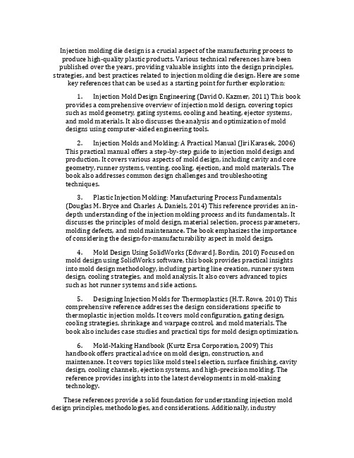
Figure 1. Organization of the IKEM Project2 Intelligent Mold Design ToolThe mold design tool in its basic form is a Visual Basic application taking input from a text file that contains information about the part and a User Input form. The text file contains information about the part geometry parsed from a Pro/E information file. The input is used to estimate the dimensions of mold and various other features.2.1 Literature ReviewDesign of molds is another stage of the injection molding process where the experience of an engineer largely helps automate the process and increase its efficiency. The issue that needs attention is the time that goes into designing the molds. Often, design engineers refer to tables and standard handbooks while designing a mold, which consumes lot of time. Also, a great deal of time goes into modeling components of the mold in standard CAD software. Differentresearchers have dealt with the issue of reducing the time it takes to design the mold in different ways. Koelsch and James have employed group technology techniques to reduce the mold design time. A unique coding system that groups a class of injection molded parts, and the tooling required ininjection molding is developed which is general and can be applied to other product lines.A software system to implement the coding system has also been developed. Attempts were also directed towards the automation of the mold design process by capturing experience and knowledge of engineers in the field. The development of a concurrent mold design system is one such approach that attempts to develop a systematic methodology for injection mold design processes in a concurrent engineering environment. The objective of their research was to develop a mold development process that facilitates concurrent engineering-based practice, andFigure 2. Organization of the Mold Design Module.While most of the input, like the number of cavities, cavity image dimensions, cycle time are based on the client specifications, other input like the plasticizing capacity, shots per minute etc., can be obtained from the machine specifications. The output of the application contains mold dimensions and other information, which clearly helps in selecting the standard mold base from catalogs. Apart from the input and output, the Figure 2 also shows the various modules that produce the final output.2.5 Framing rulesAt this stage, the expert’s knowledge is represented in the form of multiple If-Then statements. The rules may be representations of both qualitative and quantitative knowledge. By qualitative knowledge, we mean deterministic information about a problem that can be solved computationally. By qualitative we mean information that is not deterministic, but merely followed as a rule based on previous cases where the rule has worked. A typical rule is illustrated below:If Material = “Acetal” AndRunner Length <= 3 AndRunner Length > 0 ThenRunner Diameter =0.062End IfWhen framing the rules it is important that we represent the information in a compact way while avoiding redundancy, incompleteness and inconsistency. Decision tables help take care of all the above concerns by checking for redundancy and comprehensive expression of the problem statement. As an example, in the process of selecting an appropriate mold base, the size of mold base depends on the number of cavities and inserts. To ensure that all possible combinations of。
注塑模具之模具设计与制造外文文献翻译、中英文翻译
外文翻译:Injection moulding for Mold Design and ManufactureThe mold is the manufacturing industry important craft foundation, in our country, the mold manufacture belongs to the special purpose equipment manufacturing industry. China although very already starts to make the mold and the use mold, but long-term has not formed the industry. Straight stabs 0 centuries 80's later periods, the Chinese mold industry only then drives into the development speedway. Recent years, not only the state-owned mold enterprise had the very big development, the three investments enterprise, the villages and towns (individual) the mold enterprise's development also quite rapidly.Although the Chinese mold industrial development rapid, but compares with the demand, obviously falls short of demand, its main gap concentrates precisely to, large-scale, is complex, the long life mold domain. As a result of in aspect and so on mold precision, life, manufacture cycle and productivity, China and the international average horizontal and the developed country still had a bigger disparity, therefore, needed massively to import the mold every year .The Chinese mold industry except must continue to sharpen the productivity; from now on will have emphatically to the profession internal structure adjustment and the state-of-art enhancement. The structure adjustment aspect, mainly is the enterprise structure to the specialized adjustment, the product structure to center the upscale mold development, to the import and export structure improvement, center the upscale automobile cover mold forming analysis and the structure improvement, the multi-purpose compound mold and the compound processing and the laser technology in the mold design manufacture application, the high-speed cutting, the super finishing and polished the technology, the information direction develops .The recent years, the mold profession structure adjustment and the organizational reform step enlarges, mainly displayed in, large-scale, precise, was complex, the long life, center the upscale mold and the mold standard letter development speed is higher than the common mold product; The plastic mold and the compression casting moldproportion increases; Specialized mold factory quantity and its productivity increase; "The three investments" and the private enterprise develops rapidly; The joint stock system transformation step speeds up and so on. Distributes from the area looked, take Zhujiang Delta and Yangtze River delta as central southeast coastal area development quickly to mid-west area, south development quickly to north. At present develops quickest, the mold produces the most centralized province is Guangdong and Zhejiang, places such as Jiangsu, Shanghai, Anhui and Shandong also has a bigger development in recent years.Although our country mold total quantity had at present achieved the suitable scale, the mold level also has the very big enhancement, after but design manufacture horizontal overall rise and fall industry developed country and so on Yu De, America, date, France, Italy many. The current existence question and the disparity mainly display in following several aspects:(1) The total quantity falls short of demandDomestic mold assembling one rate only, about 70%. Low-grade mold, center upscale mold assembling oneself rate only has 50% about.(2) The enterprise organizational structure, the product structure, the technical structure and the import and export structure does not gatherIn our country mold production factory to be most is from the labor mold workshop which produces assembles oneself (branch factory), from produces assembles oneself the proportion to reach as high as about 60%, but the overseas mold ultra 70% is the commodity mold. The specialized mold factory mostly is "large and complete", "small and entire" organization form, but overseas mostly is "small but", "is specially small and fine". Domestic large-scale, precise, complex, the long life mold accounts for the total quantity proportion to be insufficient 30%, but overseas in 50% above 2004 years, ratio of the mold import and export is 3.7:1, the import and export balances the after net import volume to amount to 1.32 billion US dollars, is world mold net import quantity biggest country .(3) The mold product level greatly is lower than the international standardThe production cycle actually is higher than the international water broadproduct level low mainly to display in the mold precision, cavity aspect and so on surface roughness, life and structure.(4) Develops the ability badly, economic efficiency unsatisfactory our country mold enterprise technical personnel proportion lowThe level is lower, also does not take the product development, and frequently is in the passive position in the market. Our country each mold staff average year creation output value approximately, ten thousand US dollars, overseas mold industry developed country mostly 15 to10, 000 US dollars, some reach as high as 25 to10, 000 US dollars, relative is our country quite part of molds enterprises also continues to use the workshop type management with it, truly realizes the enterprise which the modernized enterprise manages fewTo create the above disparity the reason to be very many, the mold long-term has not obtained the value besides the history in as the product which should have, as well as the most state-owned enterprises mechanism cannot adapt the market economy, but also has the following several reasons: .The mold material performance, the quality and the variety question often can affect the mold quality, the life and the cost, the domestically produced molding tool steel and overseas imports the steel products to compare has a bigger disparity. Plastic,plate, equipment energy balance, also direct influence mold level enhancement.RSP ToolingRapid Solidification Process (RSP) Tooling, is a spray forming technology tailored for producing molds and dies [2-4]. The approach combines rapid solidification processing and netshape materials processing in a single step. The general concept involves converting a mold design described by a CAD file to a tooling master using a suitable rapid prototyping (RP) technology such as stereolithography. A pattern transfer is made to a castable ceramic, typically alumina or fused silica. This is followed by spray forming a thick deposit of tool steel (or other alloy) on the pattern to capture the desired shape, surface texture and detail. The resultant metal block is cooled to room temperature and separated from the pattern. Typically, the deposit’s exterior walls are machined square, allowing it to be used as an insert in a holding block such as a MUD frame [5]. The overall turnaround time for tooling is about three days, stating with a master. Molds and dies produced in this way have been used for prototype and production runs in plastic injection molding and die casting.An important benefit of RSP Tooling is that it allows molds and dies to be made early in the design cycle for a component. True prototype parts can be manufactured to assess form, fit, and function using the same process planned for production. If the part is qualified, the tooling can be run in production as conventional tooling would. Use of a digital database and RP technology allows design modifications to be easily made.Experimental ProcedureAn alumina-base ceramic (Cotronics 780 [6]) was slurry cast using a silicone rubber master die, or freeze cast using a stereolithography master. After setting up, ceramic patterns were demolded, fired in a kiln, and cooled to room temperature. H13 tool steel was induction melted under a nitrogen atmosphere, superheated about100︒C, and pressure-fed into a bench-scale converging/diverging spray nozzle, designed and constructed in-house. An inert gas atmosphere within the spray apparatus minimized in-flight oxidation of the atomized droplets as they deposited onto the tool pattern at a rate of about 200 kg/h. Gas-to-metal mass flow ratio was approximately 0.5.For tensile property and hardness evaluation, the spray-formed material was sectioned using a wire EDM and surface ground to remove a 0.05 mm thickheat-affected zone. Samples were heat treated in a furnace that was purged with nitrogen. Each sample was coated with BN and placed in a sealed metal foil packet as a precautionary measure to prevent decarburization.Artificially aged samples were soaked for 1 hour at temperatures ranging from 400 to 700︒C, and air cooled. Conventionally heat treated H13 was austenitized at 1010︒C for 30 min., air quenched, and double tempered (2 hr plus 2 hr) at 538︒C.Microhardness was measured at room temperature using a Shimadzu Type M Vickers Hardness Tester by averaging ten microindentation readings. Microstructure of the etched (3% nital) tool steel was evaluated optically using an Olympus Model PME-3 metallograph and an Amray Model 1830 scanning electron microscope. Phase composition was analyzed via energy-dispersive spectroscopy (EDS). The size distribution of overspray powder was analyzed using a Microtrac Full Range Particle Analyzer after powder samples were sieved at 200 μm to remove coarse flakes. Sample density was evaluated by water displacement using Archimedes’ principle and a Mettler balance (Model AE100).A quasi 1-D computer code developed at INEEL was used to evaluate multiphase flow behavior inside the nozzle and free jet regions. The code's basic numerical technique solves the steadystate gas flow field through an adaptive grid, conservative variables approach and treats the droplet phase in a Lagrangian manner with full aerodynamic and energetic coupling between the droplets and transport gas. The liquid metal injection system is coupled to the throat gas dynamics, and effects of heat transfer and wall friction are included. The code also includes a nonequilibriumsolidification model that permits droplet undercooling and recalescence. The code was used to map out the temperature and velocity profile of the gas and atomized droplets within the nozzle and free jet regions.Results and DiscussionSpray forming is a robust rapid tooling technology that allows tool steel molds and dies to be produced in a straightforward manner. Each was spray formed using a ceramic pattern generated from a RP master.Particle and Gas BehaviorParticle mass frequency and cumulative mass distribution plots for H13 tool steel sprays are given in Figure 1. The mass median diameter was determined to be 56 μm by interpolation of size corresponding to 50% cumulative mass. The area mean diameter and volume mean diameter were calculated to be 53 μm and 139 μm, respectively. Geometric standard deviation, d=(d84/d16)½ , is 1.8, where d84 and d16 are particle diameters corresponding to 84% and 16% cumulative mass in Figure 1.Figure1. Cumulative mass and mass frequency plots of particles in H13 tool stepsprays.Figure2 gives computational results for the multiphase velocity flow field (Figure 2a), and H13 tool steel solid fraction (Figure2b), inside the nozzle and free jetregions. Gas velocity increases until reaching the location of the shock front, at which point it precipitously decreases, eventually decaying exponentially outside the nozzle. Small droplets are easily perturbed by the velocity field, accelerating inside the nozzle and decelerating outside. After reaching their terminal velocity, larger droplets (〜150 μm) are less perturbed by the flow field due to their greater momentum.It is well known that high particle cooling rates in the spray jet (103-106 K/s) and bulk deposit (1-100 K/min) are present during spray forming [7]. Most of the particles in the spray have undergone recalescence, resulting in a solid fraction of about 0.75. Calculated solid fraction profiles of small (〜30 μm) and large (〜150 μm) droplets with distance from the nozzle inlet, are shown in Figure 2b.Spray-Formed DepositsThis high heat extraction rate reduces erosion effects at the surface of the tool pattern. This allows relatively soft, castable ceramic pattern materials to be used that would not be satisfactory candidates for conventional metal casting processes. With suitable processing conditions, fine surface detail can be successfully transferred from the pattern to spray-formed mold. Surface roughness at the molding surface is pattern dependent. Slurry-cast commercial ceramics yield a surface roughness of about 1 μm Ra, suitable for many molding applications. Deposition of tool steel onto glass plates has yielded a specular surface finish of about 0.076 μm Ra. At the current state of development, dimensional repeatability of spray-formed molds, starting with a common master, is about ±0.2%.Figure 2. Calculated particle and gas behavior in nozzle and free jet regions.(a) Velocity profile.(b) Solid fraction.ChemistryThe chemistry of H13 tool steel is designed to allow the material to withstand the temperature, pressure, abrasion, and thermal cycling associated with demanding applications such as die casting. It is the most popular die casting alloy worldwide and second most popular tool steel for plastic injection molding. The steel has low carbon content (0.4 wt.%) to promote toughness, medium chromium content (5 wt.%) to provide good resistance to high temperature softening, 1 wt% Si to improve high temperature oxidation resistance, and small molybdenum and vanadium additions (about 1%) that form stable carbides to increase resistance to erosive wear[8]. Composition analysis was performed on H13 tool steel before and after spray forming.Results, summarized in Table 1, indicate no significant variation in alloy additions.MicrostructureThe size, shape, type, and distribution of carbides found in H13 tool steel is dictated by the processing method and heat treatment. Normally the commercial steel is machined in the mill annealed condition and heat treated(austenitized/quenched/tempered) prior to use. It is typically austenitized at about 1010︒C, quenched in air or oil, and carefully tempered two or three times at 540 to 650︒C to obtain the required combination of hardness, thermal fatigue resistance, and toughness.Commercial, forged, ferritic tool steels cannot be precipitation hardened becauseafter electroslag remelting at the steel mill, ingots are cast that cool slowly and formcoarse carbides. In contrast, rapid solidification of H13 tool steel causes alloying additions to remain largely in solution and to be more uniformly distributed in the matrix [9-11]. Properties can be tailored by artificial aging or conventional heat treatment.A benefit of artificial aging is that it bypasses the specific volume changes that occur during conventional heat treatment that can lead to tool distortion. These specific volume changes occur as the matrix phase transforms from ferrite to austenite to tempered martensite and must be accounted for in the original mold design. However, they cannot always be reliably predicted. Thin sections in the insert, which may be desirable from a design and production standpoint, are oftentimes not included as the material has a tendency to slump during austenitization or distort during quenching. Tool distortion is not observed during artificial aging ofspray-formed tool steels because there is no phase transformation.注塑模具之模具设计与制造模具是制造业的重要工艺基础,在我国,模具制造属于专用设备制造业。
模具 塑料注射成型 外文翻译 外文文献 英文文献
模具塑料注射成型外文翻译外文文献英文文献XXXThere are many different processing methods used to convert plastic pellets。
powders。
and liquids into final products。
Plastic materials XXX。
thermoplastic materials XXX。
XXX require other methods。
It is XXX.XXX。
It is also the oldest method。
Suddenly。
XXX account for 30% of all XXX suitable for mass n。
when raw materials XXX in a single step of n。
In most cases。
n machiningis not required for such products。
The us products produced include toys。
automotive parts。
household items。
and electronic consumer goods.Because plastic n molds have many variable nships。
it is a complex and us processing process。
The success of XXX appropriate steps。
but on the XXX。
which leads to the n of XXX。
barrel temperature changes。
XXX ns can help ce tolerances。
ce defect rates。
and increase product quality.XXX operator is to produce products that e first-rate products in the shortest time。
模具外文翻译外文文献英文文献注塑模

模具外文翻译外文文献英文文献注塑模The Injection Molding1、The injection moldingInjection molding is principally used for the production of the thermoplastic parts,although some progress has been made in developing a method for injection molding some thermosetting materials.The problem of injection a method plastic into a mold cavity from a reservoir of melted material has been extremely difficult to solve for thermosetting plastic which cure and harden under such conditions within a few minutes.The principle of injection molding is quite similar to that of die-casting.The process consists of feeding a plastic compound in powered or granular form from a hopper through metering and melting stages and then injecting it into a mold.After a brief cooling period,the mold is opened and the solidified part ejected.Injection-molding machine operation.The advantage of injection molding are:(ⅰ)a high molding speed adapter for mass production is possible;(ⅱ)there is a wide choice of thermoplastic materials providing a variety of useful properties;(ⅲ)it is possible to mold threads,undercuts,side holes,and large thin section.2、The injection-molding machineSeveral methods are used to force or inject the melted plastic into the mold.The most commonly used system in the larger machines is the in-line reciprocating screw,as shown in Figure 2-1.The screw acts as a combination injection and plasticizing unit.As the plastic is fed to the rotating screw,it passes through three zones as shown:feed,compression,and metering.After the feed zone,the screw-flight depth is gradually reduced,force theplastic to compress.The work is converted to heat by conduction from the barrel surface.As the chamber in front of the screw becomes filled,it forces the screw back,tripping a limit switch that activates a hydraulic cylinder that forces the screw forward and injects the fluid plastic into the closed mold.An antiflowback valve presents plastic under pressure from escaping back into the screw flight.The clamping force that a machine is capable of exerting is part of the size designation and is measured in tons.A rule-of-thumb can be used to determine the tonnage required for a particular job.It is based on two tons of clamp force per square inch of projected area.If the flow pattern is difficult and the parts are thin,this may have to go to three or four tons.Many reciprocating-screw machines are capable of handing thermosetting plastic materials.Previously these materials were handled by compression or transfer molding.Thermosetting materials cure or polymerize in the mold and are ejected hot in the range of 375°C~410°C.T hermosetting parts must be allowed to cool in the mold in order or remove them without distortion. Thus thermosetting cycles can be faster.Of course the mold must be heated rather than chilled,as with thermoplastics.3、Basic Underfeed MouldA simple mould of this type is shown in Figure3-1,and the description of the design and the opening sequence follows.The mould consists of three basic parts,namely:the moving half,the floating cavity plate and the feed plate respectively.The moving half consists of The moving mould plate assembly,support block,backing plate,ejector assembly and the pin ejection system.Thus the moving half in this design is identical with the moving half of basic moulds.The floating cavity plate,which may be of the integer or insert-bolster design,is located on substantial guide pillars(not shown)fitted in the feed plate.These guide pillars must be of sufficient length to support the floating cavity plate over its full movement and still project to perform the function of alignment between the cavity and core when the mould is being closed.Guide bushes are fitted into the moving mould plate and the floating cavity plate respectively.The maximum movement of the floating cavity plate is controlled by stop or similar device.The moving mould plate is suitably bored to provide a clearance for the stop bolt assembly.The stop bolts must be long enough to provide sufficient space between the feed plate and the floating cavity plate for easy removal of the feed system.The minimum space provide for should be 65mm just sufficient for an operator to remove the feed system by hand if necessary.The desire operating sequence is for the first daylight to occur between the floating cavity plate.This ensures the sprue is pulled from the sprue bush immediately the mouldis opened.T o achieve this sequence,springs may be incorporated between the feed plate and the floating cavity plate.The springs should be strong enough to give an initial impetus to the floating cavity plate to ensure it moves away with the moving half.It is normal practice to mount the springs on the guide pillars(Figure3-2)and accommodate them in suitable pocket in the cavity plate.The major part of the feed system(runner and sprue)is accommodated in the feed plate to facilitate automatic operation,the runner should be of a trapezoidal form so that once it is pulled from the feed plate is can easily beextracted.Note that if a round runner is used,half the runner is formed in the floating cavity plate,where it would remain,and be prevented from falling or being wiped clear when the mould is opened.Now that we have considered the mould assembly in the some detail,we look at the cycle of operation for this type of mould.The impressions are filled via the feed system(Figure3-1(a))and after a suitable dwell period,the machine platens commence to open.A force is immediately exerted by the compression springs,which cause the floating cavity plate to move away with the moving half as previously discussed.The sprue is pulled from the sprue bush by the sprue puller.After the floating cavity plate has moved a predetermined distance,it is arrested by the stop bolts.The moving half continues to move back and the moldings,having shrunk on to the cores,are withdrawn from the cavities.The pin gate breaks at its junction with the runner(Figure3-1(b)).The sprue puller,being attached to the moving half,is pulled through the floating cavity plate and thereby release the feed system which is then free to fall between the floating cavity plate and the feed plate.The moving half continues to move back until the ejector system is operated and the moldings are ejected (Figure3-1(c)).When the mould is closed,the respective plates are returned to their molding position and the cycle is repeated.4、Feed SystemIt is necessary to provide a flow-way in the injection mould to connect the nozzle(of the injection machine)to each impression.This flow-way is termed the feed system.Normally thefeed system comprises a sprue,runner and gate.These terms applyequally to the flow-way itself,and to the molded material which is remove from the flow-way itself in the process of extracted the molding.A typical feed system for a four-impression,two plate-type mould is shown in Figure4-1.It is seen that the material passes through the sprue,main runner,branch runner and gate before entering the impression.As the temperature of molten plastic is lowered which going through the sprue and runner,the viscosity will rise;however,the viscosity is lowered by shear heat generated when going through the gate to fill the cavity.It is desirable to keep the distance that the material has to travel down to a minimum to reduce pressure and heat losses.It is for this reason that careful consideration must be given to the impression layout gate’s design.4.1.SprueA sprue is a channel through which to transfer molten plastic injected from the nozzle of the injector into the mold.It is a part of sprue bush,which is a separate part from the mold.4.2.RunnerA runner is a channel that guides molten plastic into the cavity of a mold.4.3.GateA gate is an entrance through which molten plastic enters the cavity.The gate has the following function:restricts the flow and the direction of molten plastic;simplifies cutting of a runner and moldings to simplify finishing of parts;quickly cools and solidifies to avoid backflow after molten plastic has filled up in the cavity.4.4.Cold slug wellThe purpose of the cold slug well,shown opposite the sprue,is theoretically to receive the material that has chilled at the front of nozzle during the cooling and ejection phase.Perhaps of greater importance is the fact that it provides position means whereby the sprue bush for ejection purposes.The sprue,the runner and the gate will be discarded after a part is complete.However,the runner and the gate are important items that affect the quality or the cost of parts.5、EjectionA molding is formed in mould by injecting a plastic melt,under pressure,into animpression via a feed system.It must therefore be removed manually.Furthermore,all thermoplastic materials contract as they solidify,which means that the molding will shrink on to the core which forms it.This shrinkage makes the molding difficult to remove. Facilities are provided on the injection machine for automatic actuation of an ejector system,and this is situated behind the moving platen.Because of this,the mould’s ejector system will be most effectively operated if placed in the moving half of the mould,i.e. the half attached to the moving platen.We have stated previously that we need to eject the molding from the core and it therefore follows that the core,too,will most satisfactorily be located in the moving half.The ejector system in a mould will be discussed under three headings,namely:(ⅰ)the ejector grid;(ⅱ)the ejector plate assembly; and(ⅲ)the method of ejection.5.1、Ejector gridThe ejector grid(Figure5-1)is that part of the mould which supports the mould plate and provides a space into which theejector plate assembly can be fitted and operated.The grid normally consists of a back plate on to which is mounted a number of conveniently shaped “support blocks”.The ejector plate assembly is that part of the mould to which the ejector element is attached.The assembly is contained in a pocket,formed by the ejector grid,directly behind the mould plate.The assembly(Figure5-2)consists of an ejector plate,a retaining plate and an ejector rod.One end of this latter member is threaded and it is screwed into the ejector plate.In this particular design the ejector rod function not only as an actuating member but also as a method of guiding the assembly.Note that the parallel portion of the ejector rod passes through an ejector rod bush fitted in the back plate of the mould.5.2、Ejection techniquesWhen a molding cools,it contracts by an amount depending on the material being processed.For a molding which has no internal form,for example,a solid rectangular block,the molding will shrink away from the cavity walls,thereby permitting a simple ejection technique to be adopted.However,when the molding has internal form,the molding,as it cools,will shrink onto the core and some positive type of ejection is necessary.The designer has several ejection techniques from which to choose,but in general,the choice will be restricted depending upon the shape of the molding.The basic ejection techniques are as follows:(ⅰ)pin ejection(ⅱ)sleeve ejection(ⅲ)stripper plate ejection and(Ⅳ)air ejection.Figure 2-1aFigure 2-1bFigure 3-1Figure 3-2Figure 4-1aFigure 4-1bFigure 5-1Figure 5-2注塑模1、注塑模尽管成型某些热固性材料的方法取得了一定的进步,但注塑模主要(还是)用来生产热塑性塑件。
注塑模具设计英文参考文献
Injection molding die design is a crucial aspect of the manufacturing process to produce high-quality plastic products. Various technical references have been published over the years, providing valuable insights into the design principles, strategies, and best practices related to injection molding die design. Here are some key references that can be used as a starting point for further exploration:1.Injection Mold Design Engineering (David O. Kazmer, 2011) This bookprovides a comprehensive overview of injection mold design, covering topics such as mold geometry, gating systems, cooling and heating, ejector systems, and mold materials. It also discusses the analysis and optimization of molddesigns using computer-aided engineering tools.2.Injection Molds and Molding: A Practical Manual (Jiri Karasek, 2006)This practical manual offers a step-by-step guide to injection mold design and production. It covers various aspects of mold design, including cavity and core geometry, runner systems, venting, cooling, ejection, and mold materials. The book also addresses common design challenges and troubleshootingtechniques.3.Plastic Injection Molding: Manufacturing Process Fundamentals(Douglas M. Bryce and Charles A. Daniels, 2014) This reference provides an in-depth understanding of the injection molding process and its fundamentals. It discusses the principles of mold design, material selection, process parameters, molding defects, and mold maintenance. The book emphasizes the importance of considering the design-for-manufacturability aspect in mold design.4.Mold Design Using SolidWorks (Edward J. Bordin, 2010) Focused onmold design using SolidWorks software, this book provides practical insights into mold design methodology, including parting line creation, runner system design, cooling strategies, and mold analysis. It also covers advanced topicssuch as hot runner systems and side actions.5.Designing Injection Molds for Thermoplastics (H.T. Rowe, 2010) Thiscomprehensive reference addresses the design considerations specific tothermoplastic injection molds. It covers mold configuration, gating design,cooling strategies, shrinkage and warpage control, and mold materials. Thebook also includes case studies and practical tips for mold design optimization.6.Mold-Making Handbook (Kurtz Ersa Corporation, 2009) Thishandbook offers practical advice on mold design, construction, andmaintenance. It covers topics like mold steel selection, surface finishing, cavity design, cooling channels, ejection systems, and high-precision molding. Thereference provides insights into the latest developments in mold-makingtechnology.These references provide a solid foundation for understanding injection mold design principles, methodologies, and considerations. Additionally, industrypublications, research papers, and case studies can offer further insights into specific design aspects, material selection, and advanced techniques. It is important to consult multiple sources and stay updated with the latest trends and advancements in injection mold design to ensure efficient and robust manufacturing processes.。
- 1、下载文档前请自行甄别文档内容的完整性,平台不提供额外的编辑、内容补充、找答案等附加服务。
- 2、"仅部分预览"的文档,不可在线预览部分如存在完整性等问题,可反馈申请退款(可完整预览的文档不适用该条件!)。
- 3、如文档侵犯您的权益,请联系客服反馈,我们会尽快为您处理(人工客服工作时间:9:00-18:30)。
导言
注塑成型工艺过程需要专业的知识、技能,最重要的是需要它成功的实践经验。通 常是工艺参数控制过程的效率。在制造过程中,有效地控制和优化这些参数能实现一致 性,这种一致性会在零件质量和零件成本上表现出来的问题。
1 智能化工程模块注塑成型工艺(IKEM)
基于知识的智能化工程模块的注塑成型工艺(IKEM)是一种软件技术,它领先于并 行工程和 CAD / CAM 系统。 它集成工程的设计和制造工艺的最新知识, 给用户各种设计 方面的指示,通过减少在产品开发设计阶段的工程变更,有助于减少一些工时。该系统 将用于注塑设计,设计迭代和流程整合。目前的过程由许多手工计算、CAD 图形结构和 从以前项目取得的经验三部分组成。一旦工程师完成设计,这将是性能评估。 该 IKEM 项目已分为三大模块。 (1) 费用估算模块 (2) 模具设计模块
2.1 文献回顾
模具设计的是另一种注塑成型过程的阶段,有经验的工程师在很大程度上有助于自 动化进程,提高其效率。这个问题需要注意的是深入研究设计模具的时间。通常情况下,
中英文资料
当设计工程师设计模具时,他们会参阅表格和标准手册,这会消耗大量的时间。另外, 在标准的 CAD 软件中需要大量的时间去考虑模具的建模组件。不同的研究人员已经解决 了缩短用不同的方式来设计模具所花费的时间的问题。凯尔奇和詹姆斯采用成组技术来 减少模具设计时间。聚合一类注塑成型件的独特的编码系统和在注射模具中所需的工具 已开发,它可以适用于其它产品生产线。实施编码系统的软件系统也已经被开发。通过 获取在这方面领域的工程师的经验和知识,尝试直接使模具设计过程的自动化。并行模 具设计系统的研究开发就是这样的一个过程,在并行工程环境中试图制定一个系统的注 塑模具设计流程。他们的研究目标是研制一个有利于并行工程实践的模具开发的进程, 和研制开发一个以知识为基础的为注塑模具设计提供工艺问题和产品要求的辅助设计。 通过各种方式获取关于模具设计过程的确定信息和不确定信息,研究人员一直试图 使模具设计流程自动化。这个研究试图研制开发一个独特的模具设计应用程序,它一确 定性和不确定性两种形式获取信息。
中英文资料
(3) 生产模块 IKEM 系统有两种形式输入。在一个 CAD 模型的形式(Pro/E 文件)下输入,和在 给出的用户界面形式下输入。图 1-1 说明了那种进入每个模块的输入形式和用户输出形 式。 制造商的经验水平将决定如何有效地控制工艺参数。有时这就导致人为错误引起的 不一致性。还有经验不足,时间、资源短缺和创新的空间不大的情况。通过创造所谓的 “智能模型”的问题,工程学知识提供了一个可行的方案去解决所有这样
2.2 采用的方法
为了发展智能模具设计工具,传统的模具设计方法在被研究。应用程序开发人员和 设计工程师合作设计一种特定塑料零件的模具。在此期间,被工程师采纳用来选择模底 座的方法正在被地密切关注和筛选过程的各个方面,需要他的知识经验来确定。此外, 有时候工程师将参考图表和手册以规范其甄选过程。这耗费时间的过程,稍后也被记录 在应用程序中。 系统的阐述依据输入和输出的应用程序是下一阶段。这涉及到如何定义什么养的模 具布局信息是用户最需要的,也是他输入最少却得到相同的输出。 根据在模具设计工作中收集到的信息,由工程师遵循的公约被转化为 if - then 规则。 决策表是用来解释各种可能出现的情况,它们是当处理模具设计工程中某一特定的方面 所提出的。这样被制定规则,然后被组织在相互交融的模块中,使用应用程序开发环境。 最后,应用程序是检验其正确性,当涉及到为塑料零件设计模具在工业生产中。
中英文资料
中英文对照外文翻译
摘要
注塑成型是一个生产热塑性塑料制品最流行的制造工艺,而模具设计是这个过程的 一个重要方面。模具设计需要专业的知识、技能,最重要的是拥有该领域的经验。三者 缺一不可。生产塑料组件需要选择恰当的模具,如果缺乏其中之一,这种选择就得在反 复试验的基础上进行。这会增加生产成本,并造成设计上的不一致。 本文介绍了智能模具设计工具的发展。该工具捕获模具设计过程的知识,并且以符 合逻辑的方式将这些知识反映出来。所获得的知识将是确定性的,但模具设计过程中的 信息是非确定的。一旦开发了模具设计工具,它将指导使用者根据不同客户的要求,为 其塑料零件选择合适的模具。
用户输入形式
模架设计
制造
ቤተ መጻሕፍቲ ባይዱ
用户输出形式
CAD 模型
语法分析程 序
成本估计
图 1-1 组织工程的 IKEM
2 智能模具设计工具
在它的基本形式中模具设计工具是一个从文本文件中提取输入的 Visual Basic 应用 程序,这种文本文件包含关于零件和用户输入程序。该文本文件包含来自 Pro/E 的一个 信息文件的零件的几何解析。输入是用来估测模具得尺寸和其它各种特性。
2.3 选择合适的模架
通常情况下,为制造塑料零件选择适当的模架所涉及的有: (1)估计模腔数 模腔数量的决定取决于在一定时间内所需部件的数量,像机器的 塑化能力,废品率等问题也会影响到模架的模腔数量。 (2)确定镶块及其尺寸 镶块有助于模架重用,因此有助于降低生产成本。当涉及 到尺寸和数量的选择,作出决定取决于现有的镶块的重用性和新的镶块的成本。 (3)确定浇道的尺寸和定位 浇道的尺寸取决于所成型的材料。尽管还有其它要考 虑材料特性来决定它的浇道的尺寸供符合它的流量要求。转轮的定位,取决于所用流道 的拓扑布局。虽然循环的浇道系统始终是最好的,支道系统的平衡,避免流道均衡补偿
中英文资料
的树枝状浇道系统是一个最被广泛应用的系统。 (4)确定浇道直径 浇道直径决定于模具的尺寸,模腔的数量或在一定的时间内用 来填补的塑料的总数。 (5)浇口的定位 塑料在某一点进入模腔,在这点可以均匀填充满模腔。浇口可以 设在循环模腔的任何周围点,但当填补矩形腔时,必须从中部流进。 (6)确定供水道的的尺寸和定位 供水道之间和从模具中的任何壁上以标准的距离 定位。该公约不是用一个直径范围定位水道在模具壁上。 (7)根据以上结论确定模具的尺寸 根据以上的所有结论,模具的大概尺寸可以被 估计,并四舍五入至最接近的产品目录号。在模架以前,如果重新设计,考虑到以上所 有方面会降低成本和减少设计时间,进入重新设计。