5700成像系统介绍-NEW1
geforce5700

GeForce 5700IntroductionThe GeForce 5700 is a graphics processing unit (GPU) developed and manufactured by NVIDIA. Released in 2003, it is part of the GeForce FX series and aims to provide high-performance graphics capabilities for gaming and multimedia applications. In this document, we will explore the features and specifications of the GeForce 5700.FeaturesThe GeForce 5700 offers a range of features designed to enhance the gaming experience and deliver stunning visuals. Some key features include:1.NVIDIA CineFX Engine: The CineFX engine provides advanced pixelshader and vertex shader technologies, enabling realistic lighting effects,realistic materials, and lifelike characters in games.2.Full DirectX 9.0 Support: The GeForce 5700 supports DirectX 9.0,ensuring compatibility with the latest games and applications that utilize this graphics API.3.Intellisample Technology: This technology improves the quality ofimages through advanced anti-aliasing techniques, reducing jagged edges and improving overall image quality.4.UltraShadow Technology: UltraShadow technology enablesadvanced shadow effects in games, improving the realism of shadows andenhancing the overall visual experience.5.Dual Monitor Support: The GeForce 5700 supports dual monitorsetups, allowing users to extend their desktop workspace or enjoy multipledisplays in games.6.NVIDIA nView Multi-Display Technology: With nView, users candynamically assign different applications to different monitors, improvingproductivity and multitasking capabilities.SpecificationsNow, let’s take a closer look at the technical specifications of the GeForce 5700:•GPU Architecture: NVIDIA NV36•Core Clock Speed: 425 MHz•Memory Type: DDR1•Memory Size: 128 MB•Memory Bandwidth: 5600 MB/s•Memory Interface: 256-bit•Shader Model Support: DirectX 9.0•OpenGL Support: 2.0The GeForce 5700 is equipped with 4 pixel pipelines and 2 vertex pipelines, providing decent performance for its time. It supports resolutions up to 2048x1536 and can handle most games of the early 2000s with ease.PerformanceIn terms of performance, the GeForce 5700 offers respectable gaming capabilities for its era. It was able to handle popular games of that time, such as Half-Life 2 and Doom 3, at decent frame rates and image quality settings. However, as newer and more demanding games were released, the GeForce 5700 started to show its limitations.ConclusionThe GeForce 5700 was a mid-range graphics card released by NVIDIA in 2003. It offered a range of features and specifications that aimed to deliver high-quality graphics for gaming and multimedia applications. While it may not hold up to modern standards, it was a capable graphics card during its time and provided a satisfactory gaming experience.。
5700 series displays说明书
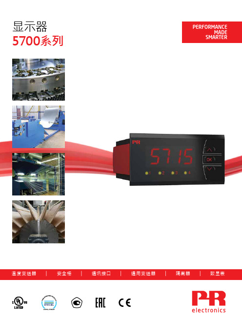
显示器5700系列温度变送器 | 安全栅 | 通讯接口 | 通用变送器 | 隔离器 | 数显表注重效率加工行业提出了要持续注重效率的口号,因此,确保可靠和极其精确的信号调节是保持高效率的绝对必要的先决条件。
佩勒电子公司已经敏锐地嗅到这一市场机遇,因此,自 1974 年以来,该公司已经开发和制造出适用于信号调节和过程控制的模块。
今天,该公司已经成为可提供5年担保期的少数几个公司之一。
5700系列显示器5714, 5715和5725 (1/8 DIN, 96x48 mm)型号的显示器可达到最高效率的加工同时满足用于通用、用户友好和可靠显示器的用户要求。
5714和5715型号有一个模拟信号和温度信号的通用输入端口而5725型号有一个脉冲信号通用输入端口。
量身打造的OEM解决方案在5714、5715和5725型号的前端和其改进机构上刻印有自有品牌标记。
输入信号线性化是为OEM客户提供的另一功能。
及时性5714、5715和5725型号为佩勒电子公司市场知识和创新产品开发的结晶。
在丹麦总部对生产设施进行了开发、测试和生产,以确保对所有佩勒电子模块的日常交付。
45714A 5714B 5714C 5714D ✓✓✓✓✓✓✓✓✓✓✓✓5715B 5715D ✓✓✓✓✓✓✓✓✓✓✓✓✓✓✓✓✓✓✓✓✓✓✓✓✓5725D✓✓✓5725A ✓✓固定:独特的PRdesigned紧固系统确保了显示器和面板之间最佳的密封性。
侧面标签:位于模块上的详细的安装指南,以确保用户随时都能够阅读到这些信息。
多种语言:通过滚动显示器上的帮助文本可显示8种语言。
PReset:5715型号可通过计算机和我们的Preset软件进行编程,因此可提供附加功能,比如线性化和偏移。
PReset可允许您轻松快速地对显示器的任意数量进行配置。
通用频率/脉冲输入0...50 kHz mA输入:0/4...20 mAV输入:0/0.2...1 V / 0...10 V / 2...10 V RTD:2、3和4线TC类型:B...W5电位计:10 Ω...100 kΩ2*继电器:250 VRMS / 2 A 4*继电器:250 VRMS / 2 A mA输出:20 mA / 800 Ω / 16 VDC输入输出规格立即从“更加智能化的运作”受益PR电子是一家领先的科技公司,专注于使工业过程控制更加安全、可靠、高效。
华为企业网络产品介绍

HUAWEI TECHNOLOGIES CO., LTD.
Huawei Confidential
Page 6
Huawei Enterprise A Better Way
超绿色节能二层千兆交换机:S5700-LI
Power consumption (Watts)
Huawei vs. other vendor 60
Huawei Enterprise A Better Way
端口多、密度高 5710-EI 最高支持8*10GE,整机最高支持64GE
5710HI后续将推出96GE+8*10GE+4*40GE
故障收敛速度快
5700HI支持硬件ETH OAM和BFD,50ms故障收敛 5700全系列支持SEP,50ms故障收敛,灵活组网
3 WLAN助力企业构建无线融智网络 4 eSight 推进企业网络一体化运维 5 工具和网站介绍
SOHO分支---总部的全系列路由器
50
46.3
47
48
48.2
40
39.6
30 20
35.3
29
24.6
28.6
17.3
10
12.5
0
0
Hibernation No_Link
Idle(0%) TR_30%
S5700-52P-LI
TR_70% TR_100%
Other vendor
单设备每年节能150kwh,能耗降低69%
设备及IP网络节能
业务性能好
5700HI支持MPLS, 超高性价比PE设备
用电省,绿色环保
5700LI支持SSS-Energy精细化节能技术,支持整机休眠, 能耗较业界降低69%
阿尔伦-布拉德利 Stratix 5700 工业 managed Ethernet 交换机说明书
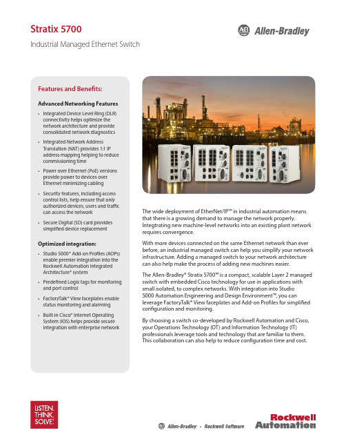
Stratix 5700Industrial Managed Ethernet SwitchThe wide deployment of EtherNet/IP™ in industrial automation means that there is a growing demand to manage the network properly.Integtrating new machine-level networks into an existing plant network requires convergence.With more devices connected on the same Ethernet network than ever before, an industrial managed switch can help you simplify your network infrastructure. Adding a managed switch to your network architecture can also help make the process of adding new machines easier. The Allen-Bradley® Stratix 5700™ is a compact, scalable Layer 2 managed switch with embedded Cisco technology for use in applications with small isolated, to complex networks. With integration into Studio 5000 Automation Engineering and Design Environment™, you canleverage FactoryTalk® View faceplates and Add-on Profiles for simplified configuration and monitoring.By choosing a switch co-developed by Rockwell Automation and Cisco, your Operations Technology (OT) and Information Technology (IT) professionals leverage tools and technology that are familiar to them. This collaboration can also help to reduce configuration time and cost.Features and Benefits:Advanced Networking Features• Integrated Device Level Ring (DLR) connectivity helps optimize the network architecture and provide consolidated network diagnostics • Integrated Network Address Translation (NAT) provides 1:1 IP address mapping helping to reduce commissioning time • Power over Ethernet (PoE) versions provide power to devices over Ethernet minimizing cabling • Security features, including access control lists, help ensure that only authorized devices, users and traffic can access the network • Secure Digital (SD) card provides simplified device replacementOptimized integration:• Studio 5000® Add-on Profiles (AOPs) enable premier integration into the Rockwell Automation Integrated Architecture® system • Predefined Logix tags for monitoring and port control • FactoryTalk® View faceplates enable status monitoring and alarming • Built-in Cisco® Internet Operating System (IOS) helps provide secure integration with enterprise networkDesigned and Developed for EtherNet/IP Automation ApplicationsNetwork Address TranslationMachine integration onto a plant network architecture can be difficult as machine builder IP-address assignments rarely match the addresses of the end-user network. Also, network IP addresses are often unknown until the machine is being installed. The Stratix 5700 with Network Address Translation (NAT) is a Layer 2 implementation that provides “wire speed” 1:1 translations ideal for automation applications where performance is critical.NAT allows for:• Simplified integration of IP-addressmapping from a set of local,machine-level IP addresses to theend user’s broader plant network• OEMs to deliver standard machinesto end users without programmingunique IP addresses• End users to more simply integratethe machines into the larger network192.168.1.4192.168.1.4MACHINE 1MACHINE 2Private Network Private NetworkSwitch Reference ChartAllen-Bradley Stratix 5700 Industrial Ethernet SwitchSwitch Selection TableFE - Fast Ethernet GE - Gigabit EthernetPublication ENET-PP005F-EN-E – April 2016Copyright ©2016 Rockwell Automation, Inc. All Rights Reserved. Printed in USA.Supersedes Publication ENET-PP005E-EN-E – March 2015EtherNet/IP is a trademark of the ODVA.Cisco is a trademark of Cisco Systems, Inc.Allen-Bradley, CompactLogix, Factory Talk, Integrated Architecture, Kinetix, LISTEN. THINK. SOLVE., Powerflex, Rockwell Automation, Rockwell Software, Stratix 5700, Studio 5000, Studio 5000 Automation Engineering and Design Environment are trademarks of Rockwell Automation, Inc.Glossary of TermsAccess Control Lists allow you to filter network traffic. This can be used to selectively block types of traffic to provide traffic flow control or provide a basic level of security for accessing your network.CIP port control and fault detection allows for port access based on Logix controller program or controller mode (idle/fault). Allows secure access to the network based on machine conditions.CIP SYNC (IEEE1588) is the ODVAimplementation of the IEEE 1588 precision time protocol. This protocol allows very high precision clock synchronization across automation devices. CIP SYNC is an enabling technology for time-critical automation tasks such as accurate alarming for post-event diagnostics, precision motion and high precision first fault detection or sequence of events.Device Level Ring (DLR) allows direct connectivity to a resilient ring network at the device level.DHCP per port allows you to assign a specific IP address to each port, confirming that the device attached to a given port will get the same IP address. This feature allows for device replacement without having to manually configure IP addresses.Encryption provides network security by encrypting administrator traffic during Telnet and SNMP sessions.EtherChannel is a port trunking technology. EtherChannel allows grouping several physical Ethernet ports to create one logical Ethernet port. Should a link fail, the EtherChannel technology will automatically redistribute traffic across the remaining links.Ethernet/IP (CIP) interface enables premier integration to the Integrated Architecture with Studio 5000 AOP , Logix tags and View Faceplates.FlexLinks provides resiliency with a quick recovery time and load balancing on a redundant star network.IGMP Snooping (Internet Group Management Protocol) constrains the flooding of multicast traffic by dynamically configuring switch ports so that multicast traffic is forwarded only to ports associated with a particular IP multicast group.* Separate SW IOS requiredKey Software FeaturesMAC ID Port Security checks the MAC ID of devices connected to the switch to determine if it is authorized. If not the device is blocked and the controller receives a warning message. This provides a method to block unauthorized access to the network.Network Address Translation (NAT) provides 1:1 translations of IP addresses from one subnet to another. Can be used to integrate machines into an existing network architecture.Port Thresholds(Storm control & Traffic Shaping)allows you to set both incoming and outgoing traffic limits. If a threshold is exceeded alarms can be set in the Logix controller to alert an operator. Power over Ethernet (PoE) provides electrical power along with data on a single Ethernet cable to end devices.QoS – Quality of Service (QoS) is the ability to provide different priority to different applications, users, or data flows, to help provide a higher level of determinism on your network.REP (Resilient Ethernet Protocol) – A ring protocol that allows switches to be connected in a ring, ring segment or nested ring segments. REP provides network resiliency across switches with a rapid recovery time ideal for industrial automation applications.Smartports provide a set of configurations to optimize port settings for common devices like automation devices, switches, routers, PCs and wireless devices. Smartports can also be customized for specific needs.SNMP Simple Network Management Protocol (SNMP) is a management protocol typically used by IT to help monitor and configure network-attached devices.Static and InterVLAN Routing bridges the gap between layer 2 and layer 3 routing providing limited static and connected routes across VLANs.STP/RSTP/MST Spanning Tree Protocol, is a feature that provides a resilient path between switches. Used for applications that requires a fault tolerant network.VLANs with Trunking is a feature that allows you to group devices with a common set of requirements into network segments. VLANs can be used to provide scalability, security and management to your network.802.1x Security is an IEEE standard for access control and authentication. It can be used to track access to network resources and helps secure the network infrastructure.。
5700测井技术介绍
ECLIPS-5700测井服务项目l数字井周声波成像测井l微电阻率井壁扫描成像测井l磁共振成像测井l薄层电阻率测井l多极阵列声波测井l正交偶极声波测井l高分辨率阵列感应测井l分区水泥胶结测井薄层电阻率测井——TBRT耐压(M P A)最大井眼(m m)最小井眼( m m)138558.6152TBRT应用实例l Q14井:l利用RTBR-RMLL交会图直观识别油气层。
TBRT应用实例l Q14井:l对于厚层,薄层电阻率与深侧向电阻率二者基本相同,但致密钙层在这类砂泥岩厚层的细分上利用薄层电阻率测井可以很容易识别,高阻致密钙层的RTTB远大于RD。
TBRT应用实例l Q14井:l对于厚度薄的油气层,RTTB的值远远大于深侧向电阻率RD。
l40、b1、41层RD为12-30Ωm,三孔隙度曲线没有可靠的油气指示,但RTTB达60-70Ωm以上。
三层试油,日产气51396方,累计产气39519方。
应用TBRT识别、评价薄油气层的局限l在泥浆侵入不太深的一般情况下,薄层电阻率测井对油气层有着更为优越的识别能力。
l但在泥浆侵入较深层段,由于受探测范围限制,薄层电阻率与原状地层电阻率相差较多。
这时应使用横向探测深度较大的常规双侧向测井值计算地层流体饱和度。
耐压(MPa)最大井眼(mm)最小井眼(mm)137.9533114 137.9533123MAC全波列采集l MAC仪器的单极阵列和偶极阵列各由8个接收器构成,其发射器各有两个. 在全波列测井方式下,可同时记录两套全波列和两条时差△t曲线(2ft和6in分辨率). 由单极全波列可提取纵波、横波、斯通利波等;由偶极阵列的全波列可提取地层挠曲横波.l W60-38-46井:l MAC记录的2ft时差曲线及6in时差曲线与常规声波时差曲线的直观对比。
MAC 应用实例l S116井:l利用MAC的全波列提取纵波、横波、斯通利波等的慢度、波形幅度、波至时间及衰减等,据此可以评价地层的岩性、裂缝、渗透性等特征。
ECLIPS-5700系统介绍

ECLIPS硬件系统
模块功能及信号流程
塔里木勘探开发研究院 测井中心
2004年1月18日
目录
目录
➢前 言 ➢ 第一章 ECLIPS测井系统功能简述 ➢ 第二章 地面硬件系统组成 ➢ 第三章 ECLIPS 系统及信号流图 ➢ 第四章 数字采集处理系统 ➢ 第五章 ECLIPS-S系统总线类型及特征
第一章
目前ECLIPS-5700常用测井项目如下: 1. 常规项目 (1)电法测井系列(MLL/DLL/TBRT); (2)声波测井系列(DAL); (3) 放 射 性 测 井 系 列 ( ZDL/CN/GR/DSL);
第一章
2.特殊项目 (1)微电阻率成像(STAR); (2)数字声波井周成像(DCBIL); (3)交叉偶极子阵列声波(XMAC); (4)高分辨率感应测井(HDIL); (5)地层倾角测井(DIPLOG);
❖ 扬声器插座---连接至外部扬声器;
第四章
❖ HP 并行端口(未用);
❖ 连接到内部SCSI总线的SCSI Π总线;
❖ 系统图形卡RGB视频端口---连接到5754彩色显 示器;
❖ LAN(AUI)端口---连接到(MAU)内部以太网 模块;
两台显示器(MONITOR)。监察正被记 录处理的测井数据和监控所有的测井操作。
第二章
打印机/绘图仪(PLOTTER),提供给用 户显示所有井况处理数据的硬拷贝。
通讯调制解调器(Modem)接口,通过电 话线,无线电台或卫星,可以将数据发送 到远方地面站。
外接式附属处理器,可以通过以太网连 接到主系统,以执行特定任务。
它通过曼彻斯特码命令字控制仪器工作 方式,数据采集以及信号收发,并可对资 料进行解释处理、显示、存储等。
浙江恒光电子EH-TW5700项目器说明书
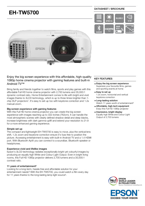
EH-TW5700DATASHEET / BROCHUREEnjoy the big screen experience with this affordable, high-quality1080p home cinema projector with gaming features and built-inAndroid TV™Bring family and friends together to watch films, sports and play games with thisaffordable Full HD home cinema projector with 2,700 lumens and 35,000:1 dynamic contrast ratio. Home Entertainment comes to life with bright and vivid images thanks to 3LCD technology, which is up to three times brighter than 1-chip DLP projectors¹. It’s easy to set-up too with keystone correction and 1.2x manual zoom.Big screen experience with gaming featuresWith this Full HD home cinema projector you can create the big screenexperience with images reaching up to 332 inches (762cm). It can handle the most atmospheric scenes with clearly defined shadow detail and deep blacks, increase brightness with dark gamma uplift and extend your resolution to 21:9 for a more enhanced gaming experience.Simple set upThe compact and lightweight EH-TW5700 is easy to move, plus the vertical lens shift, 1.2x zoom and keystone correction ensure it’s fuss free to position thepicture. Accessing entertainment is easy with built-in Android TV and a 1.4 HDMI port. With Bluetooth AptX you can connect to a soundbar, Bluetooth speaker or headphones.Experience vivid and lifelike imagesEpson’s 3LCD technology radiates exceptionally bright yet colourful images by producing an equally high White and Colour Light Output. Even in bright living rooms, this Full HD 1080p projector delivers 2,700 lumens and a 35,000:1 contrast ratio.11 years of entertainment²Looking for a long-term, hassle-free and affordable solution for yourentertainment needs? With the EH-TW5700, you could watch a film every day for 11 years thanks to the long-lasting lamp light source².KEY FEATURESEnjoy the big screen experience Supersize your favourite films, games and sporting events at home Easy to set up1.2x zoom, horizontal and vertical keystone correction Long-lasting solutionWatch 11 years worth of entertainment²Affordable, high-tech equipment Enjoy this Full HD 1080p projector Impressive, bright displayEqually high White and Colour LightOutput of 2,700 lumensPRODUCT SPECIFICATIONSTECHNOLOGYProjection System3LCD Technology, RGB liquid crystal shutterLCD Panel0.61 inch with C2 FineIMAGEColor Light Output2,700 Lumen- 1,780 Lumen (economy) In accordance with ISO 21118:2013White Light Output2,700 Lumen - 1,780 Lumen (economy) In accordance with ISO 21118:2013Resolution Full HD 1080p, 1920 x 1080, 16:9Native Contrast35,000 : 1Lamp UHE, 200 W, 4,500 h durability, 7,500 h durability (economy mode)Keystone Correction Auto vertical: ± 30 °, Manual horizontal ± 30 °Colour Reproduction Upto 1.07 billion coloursHigh Definition Full HD 3DAspect Ratio16:9OPTICALThrow Ratio 1.22 - 1.47:1Zoom Manual, Factor: 1 - 1.2Screen Size34 inches - 332 inchesProjection Distance Wide/Tele2.17 m - 2.61 m ( 80 inch screenProjection Lens Focal Length16.9 mm - 20.28 mmProjection Lens Focus ManualCONNECTIVITYInterfaces USB 2.0 Type B (Service Only), HDMI 1.4, Stereo mini jack audio out, BluetoothADVANCED FEATURES3D Active2D Colour Modes Dynamic, Natural, Cinema, Bright Cinema3D Colour Modes3D Dynamic, 3D CinemaOther features3D depth adjustment, AV Mute Slide, Android TV, Automatic keystone correction, Built-inspeaker, Frame interpolation, Game mode, Horizontal and vertical keystone correction, Longlamp life, Quick CornerGENERALPower consumption297 Watt, 227 Watt (economy), 0.3 Watt (standby), On mode power consumption as defined in JBMS-84 262 WattHeat Dissipation1,009.8 BTU/hour (max)Product dimensions309 x 315 x 122 mm (Width x Depth x Height)Product weight 3.6 kgNoise Level Normal: 36 dB (A) - Economy: 28 dB (A)Loudspeaker10 WattRoom Type / Application Gaming, Home Cinema, Home Photo, Sports, Streaming, TV & Box setsPositioning Ceiling Mounted, DesktopColour WhiteOTHERWarranty24 months Carry in, Lamp: 36 months or 3,000 hEH-TW5700WHAT'S IN THE BOXRemote control incl. batteries Power cableUser manual (CD)Warranty cardMain unitOPTIONAL ACCESSORIESScreen (80" Multi-Aspect) - ELPSC26V12H002S26Safety Wire - ELPWR01V12H003W01Ceiling Pipe (700mm) - ELPFP14V12H003P14Ceiling Pipe (450mm) - ELPFP13V12H003P13Ceiling Mount (White) - ELPMB23V12H003B23Lamp - ELPLP97 - EB9XX/W49/X/E20/U50 (2020 models) V13H010L97Screen (50" Desktop type) - ELPSC32V12H002S32Screen (80" Mobile X type16:9) - ELPSC21V12H002S21LOGISTICS INFORMATIONSKU V11HA12040 EAN code8715946686684Country of OriginPhilippinesEH-TW57001. Android TV™2. Google, Google Play, YouTube, and Android TV aretrademarks of Google LLC.3.4. Color brightness(color light output) in brightestmode, measured by a third-party lab in accordance withIDMS 15.4. Color brightness will vary depending on usageconditions. Top-selling Epson 3LCD projectors versus topselling 1-chip DLP projectors based on NPD sales data forMay 2017 – April 2018. 2) Based on watching an average 1hr45mins film every day and the lamp set in Eco mode.Homeusers************Web: For more information please contact:。
DV5700使用手册
User’s GuideCarestream Health, Inc.150 Verona StreetRochester, New York 14608© Carestream Health, Inc., 2011 Pub No. 9G3886_enRev. ATable of Contents1 OverviewMajor internal assemblies............................................................................................................................... 1-2 How the laser imager works ............................................................................................................................1-3 Film sizes ........................................................................................................................................................1-4 Automatic image quality and processing ..........................................................................................................1-4 Configuring and monitoring the system (using the Web Portal) .......................................................................1-4 Enhancing serviceability with remote monitoring ............................................................................................1-5 Agency compliance......................................................................................................................................... 1-5 User guide conventions ...................................................................................................................................1-5 2 Basic Operating TasksUnderstanding the display screen ....................................................................................................................2-2 Turning the power on and off ..........................................................................................................................2-3 Working with film cartridges ...........................................................................................................................2-5 Deleting pending jobs .....................................................................................................................................2-8 Making a test print ..........................................................................................................................................2-8 Calibrating the laser imager for the installed film ............................................................................................2-9 Opening or removing a cover ..........................................................................................................................2-9 Using the Web Portal to access additional functionality .................................................................................2-10 3 Maintenance and TroubleshootingOverview: Status and error messages and codes ..............................................................................................3-1 Preventive maintenance ...................................................................................................................................3-2 Error indicators on the display screen ............................................................................................................3-4 Using the Web Portal to gain more information on errors .............................................................................. 3-5 Subsystem error codes and messages ..............................................................................................................3-5 Condition codes ..............................................................................................................................................3-9 Correcting film jams ......................................................................................................................................3-14 Display Screen is not functional ....................................................................................................................3-18 Calling for support ........................................................................................................................................3-18 4 Film Technical InformationGeneral description .........................................................................................................................................4-1i5 SpecificationsEquipment Specifications ................................................................................................................................5-1 Operating Space Requirements .......................................................................................................................5-1 Environmental Requirements ..........................................................................................................................5-1 Environmental Effects .....................................................................................................................................5-2 Power Requirements .......................................................................................................................................5-2 Network Requirements ...................................................................................................................................5-2 iiOverview2011-03-319G3886_en 1-11OverviewThe Laser Imaging System is a continuous-tone laser imager with aninternal photothermographic film processor. Heat, rather than photochemicals, is used to develop the film. This easy-to-use and reliable laserimager provides high quality prints. Use the prints from this system for:•Diagnostic purposes to determine patient treatments•Referral, sharing, or educational purposesThe system receives and prints from image sources such as medicalelectrical equipment (modalities) and workstations over the network.You can send print jobs simultaneously from multiple image sources.The open design lets you connect to modalities of all types and vendors.IMPORTANT: Install the printing system in a secure location to protect patient privacy rights if required by local regulations.1Top cover . Covers the processor rollers. The top cover is interlocked.2Display screen . Your interface to the laser imager. Provides status and error information.3Right cover . Protects sensitive electronic equipment. The right cover is interlocked and is only accessed by service personnel.4Film supply . Install film cartridges here. Supports four film sizes. 5Left cover . You might remove the left cover to clear an occasional film jam. The left cover is interlocked.6Power switch . The power switch is on the back.7Exit tray . Extend the exit tray to hold large film (35 x 43 cm, or 14 x 17 in.) as it finishes printing. It can hold up to 50 processed sheets of film.4712356OverviewMajor internal assemblies1Exposure transport. Moves the film past the scanning laser beam.2Transport guides. Orient and center the film while moving the film from the supply to the imaging portion of the laser imager.3DICOM Raster Engine (DRE). A computer board that receives, processes, and manages the images. 4Feed rollers. Move the film through the laser imager.5Processor rollers. The processor uses heat to develop the image written onto the film by the laser in the optics module. The rollers move the film through the processor assembly, holding the film against the processor drum.6Processor drum. Provides the heat that processes the image on the film.7Airflow manifolds. Remove heat and processing odors from the processor assembly.8Pickup assembly. Lifts a single sheet of film from the supply cartridge and feeds it into the rollers.9Exit rollers. Moves the film from the processor area to the exit tray.10Rollback assembly. Rolls the film cartridge cover back so the pickup assembly can lift the film. When the laser imager is not printing, the cover is closed over the film cartridge to protect the film from light. 11Charcoal filter. Absorbs the odors caused by heat processing.12Optics module. Writes the image onto the film while the film is moved through the exposure transport. 13Accumulator. The film feeds into the accumulator as it is imaged. When imaging is complete, the filmis sent from the accumulator up to the processor assembly where the heat is applied to process the image.1-29G3886_en2011-03-31OverviewHow the laser imager worksThe laser imager receives, processes, manages, and prints the images onfilm. The laser imager has limited storage to hold a small number ofdigital images. As images are received for printing, they are stored inmemory, placed in a sequential print queue, and are printed in order. Thelaser imager can continue to accept incoming print jobs even iftemporarily unable to print (if the film supply is empty, etc).During normal operation, the laser imager requires very little attention. Itprints automatically in response to print requests from the configuredimage sources. Information sent with the images by the image source,such as film type and size and image quality settings, is applied unlessyou set the laser imager to override information that comes from theimage source.Print sequence1.Suction cups in the pickup area lift a single sheet of film out of thesupply cartridge and feed the film into the transport rollers.2.The transport rollers move the film down into the exposure transportarea.3.The film moves down during imaging (as the optics module writesthe image onto film), reverses direction at the conclusion ofimaging, and then the film moves up into the processor.4.As the film passes over the processor drum, the heat generated bythe drum develops the film.5.The exit rollers move the developed film to the exit tray.2011-03-319G3886_en1-3OverviewFilm sizesThe laser imager supports four sizes:•35 x 43 cm (14 x 17 in.)•28 x 35 cm (11 x 14 in.)•25 x 30 cm (10 x 12 in.)•20 x 25 cm (8 x 10 in.)For the specific films that are supported, see the Publications CoverPage.Automatic image quality and processingAn internal densitometer enables the laser imager to automatically adjustimage processing parameters (Automatic Image Quality Control, orAIQC) to produce an optimal image. The laser imager adjusts theseparameters each time it prints a calibration film.A calibration film is printed when:•The film tray is inserted in the laser imager with film of a new lotnumber.•You request a calibration film at the display screen or the WebPortal. For more information, see “Calibrating the laser imager forthe installed film” on page2-9.• A film cartridge is inserted into the laser imager for which a currentcalibration is not stored.Configuring and monitoring the system (using the Web Portal)The Web Portal is your interface to additional features. In addition tothe installation and setup of your system, you can view and manage thelaser imager's connections over the network, configure features, viewerror messages, and access general status information at the Web Portal.You can also check film count, film size, and film type.For more information, see “Accessing the Web Portal” on page2-10.1-49G3886_en2011-03-31Overview2011-03-319G3886_en 1-5Enhancing serviceability with remote monitoringRemote Management Services is set up through the Web Portal, and isdesigned to enhance efficient system serviceability and simplifyanalytical and service processes through the monitoring of yourequipment. Additionally, this simplifies the service process by providingqualified service personnel with faster, easier, and more complete accessto the operational history of each system.Remote Management Services provides the following for the laserimager:•Ability to monitor and diagnose error conditions withoutintroducing “downtime”•Firewall-safe, Internet transmission of machine data, whilecomplying with patient confidentiality regulations•Minimal effort to set up communication•Flexibility to facilitate specific configurations at each siteAgency complianceSee the Safety Manual.User guide conventionsThe following special messages emphasize information or indicatepotential risks to personnel or equipment.NOTE: Notes provide additional information, such as expanded explanations, hints, or reminders.IMPORTANT: Important notes highlight critical policy information that affects how you use this guide and this product.CAUTION :Cautions point out procedures that you must follow precisely toavoid damage to the system or any of its components, loss ofdata, or corruption of files in software applications.DANGER: DANGER IDENTIFIES PROCEDURES THAT YOU MUST FOLLOW PRECISELY TO AVOID INJURY TO YOURSELF OR SER WARNING :Laser warnings warn personnel that access to laser radiation ispossible and all personnel must avoid direct exposure to thebeam.2Basic Operating TasksDuring normal operation, the laser imager receives and automaticallyprints images sent by modalities over a network. Very little interaction isrequired. You may do the following:•Turn the power on (|) and off (0).•Load film cartridges.•Monitor the display screen for status and operating conditions.Sometimes it will be necessary to perform preventive maintenance, filterreplacement, and other corrective actions such as a restart. (See“Chapter3 Maintenance and Troubleshooting”.)You also may access the Web Portal to perform additional configuration,optimize image quality, or do troubleshooting tasks. (See page2-10.)Understanding the display screenThe display screen communicates the status of the laser imager. Symbol or code Description Top left of the display screen:Error or status code. The 3-digit code displays when the error or status condition is present. See “Chapter 3 Maintenance and Troubleshooting” for a complete list of the codes and how to resolve them. If the laser imager is on and a 3-digit code does not display, the laser imager is operating normally.If a different film size has been requested than what is installed, the requested film size displays. See “Loading a different film size to match a print request” on page 2-7.Lower left of the display screen:Film count. Displays the number of films that are remaining in the film cartridge. The loaded film size also displays in this location.Power When the symbol is green, the power is on and the laser imager is ready to print. The symbol flashes while the laser imager is processing.When the symbol is yellow, the laser imager is not ready to print. Examples are when the laser imager is warming up or when the film cartridge is empty.Calibrate Press to initiate film calibration. The symbol flashes while the calibration is in process. See “Calibrating the laser imager for the installed film” on page 2-9.Pause During normal operation, the symbol is off. When the film cartridge cover is open, the symbol is on. To avoid exposing the film to light, do not open the film supply until thesymbol is off.If the Pause symbol is on, you can press the symbol to temporarily pause printing. Any jobs in progress finish printing, then the film cartridge cover closes.Wait until the Pause symbol is off for cartridge replacement, etc.Film Size When the symbol appears, the requested job requires a different film size. See “Loading a different film size to match a print request” on page 2-7.You can also delete a print request. See “Deleting pending jobs” on page 2-8.Restart Restart the laser imager. An error code also displays. See “Restarting the laser imager” on page 2-4.Film Jam Film is jammed. The error code confirms the film jam and gives direction on where to find the film inside the laser imager. See “Film jams” on page 3-4.MaintenancePreventive maintenance is required. Check the error code to learn what action to take. See “Preventive maintenance” on page 3-2.Turning the power on and offTo start the laser imager, press the power switch on the back of the laserimager to on (|). Wait as the laser imager warms up. The warm-up periodmight last up to 30 minutes. The display screen shows the progress as thelaser imager becomes ready to print.Warming upThe warm-up period varies depending on the amount of time the laserimager has been off and the ambient temperature. During warm-up, thelaser imager can receive and store images but cannot print films.When the laser imager reaches operating temperature, the display screenchanges to show that the system is ready to print, and the laser imagerprints images that were received during the warm-up period.Ready to printEmergency shutdownor power loss In the event of a power loss, or if an emergency requires an immediateshutdown of the laser imager, films in process will not be completed.However, when power is restored, the laser imager will restart. Afterwarming up, the laser imager automatically reprints any films that werein process when the power was interrupted.The power symbol isyellow and flashingwhile the laser imager warms up A countdown to zero (0) indicates how soon the laser imager will be ready to print Film countGreen power symbol means "ready"You cancalibrate the filmcartridge ifnecessaryRestarting the laser imager If the laser imager encounters an error that is usually corrected with a restart, the display screen shows the Restart symbol.1.Press the power switch on the back of the laser imager off (0).2.Press the power switch on (|).If the error does not clear with after the restart, it might be necessaryto contact a qualified service provider.RestartThe error code indicates the error condition. You may want to check the “Troubleshooting” chapter or the Quick Reference Card to identify the error.Working with film cartridgesChecking film count The film count displays on the laser imager display screen.Checking the size ofthe loaded film The film size displays in the same location as the film count. The displayscreen alternates between the film count and the size of the loaded film.Film count is flashing"0"When the film cartridge is empty, the film count flashes "0" and thepower symbol is yellow, which indicates that the laser imager cannotprint. Replace the film cartridge with a new one with the appropriate sizefilm. See page 2-6.Film count125 indicates a full cartridgeFilm size"35" indicates the 1st dimension of thefilm cartridge. For example, "35" then"43" appears if 35 x 43 cm film isloaded. Then the film count displaysagain.When the film count is "0", youmust replace the film cartridgebefore you can print againInserting a new film cartridge Before you insert a new film cartridge, make sure that the Pause symbol is off. During normal operation, the symbol is off. When the film cartridge cover is open, the symbol is on. To avoid exposing the film to light, do not open the film supply until the Pause symbol is off.If the Pause symbol is on, press the symbol to close the film cartridge cover.1.Open the film supply. Hold the edges of the film cartridge and liftthe empty cartridge out of the film supply.2.Discard the removed cartridge.3.Insert the new film cartridge. Align the cartridge with the labelfacing up and the perforations to the front. Set the leading edge on the cartridge guides, and then slide the film cartridge into the laser imager to engage the detents in the bottom of the cartridge.4.Close the film supply.5.Check that the display screen changes to reflect the new film count. Make sure the Pause symbol is off (not illuminated)before you insert a new film cartridge.Pause symbol is on Pause symbol is offFilm SupplyLoading a differentfilm size to match aprint request If a print request requires a different film size, the requested film size flashes on the display screen. Change the installed film to match the print request.1.If the Pause symbol is on, press it and wait until it goes off.2.Open the film supply. Hold the edges of the film cartridge and liftthe cartridge out of the film supply.3.Store the removed film cartridge.4.Insert the new film cartridge. Align the cartridge with the labelfacing up and the perforations to the front. Set the leading edge onthe cartridge guides, and then slide the film cartridge into the laserimager to engage the detents in the bottom of the cartridge.5.Close the film supply.6.Check that the display screen changes to reflect the new film size.The requested filmsize flashes. In thisexample, load35 x 43 cm(14 x 17 in.) film.The Film Size symbolindicates that youmust change the film size.Screen 1: "35" flashes Screen 2: "43" flashesIn most cases, the Pause symbol is off. Do not open the filmsupply if the Pause symbol is on. The Pause symbol indicatesthat the film cartridge is open.Deleting pending jobsTo cancel all print requests, press and hold the Film Size symbol for fiveseconds. All print requests are deleted from the queue.NOTE:• A print request that cannot be printed is automatically deletedfrom the laser imager. This situation could be caused byinvalid parameters from the modality, etc.•If a job is not printable, the laser printer will eject a blankfilm into the exit tray.Making a test printNOTE: You can make additional test prints at the Web Portal. For more information, see “Accessing the Web Portal” on page 2-10.Make a SMPTE test from the laser imager to check that you can print.Press and then release the Calibration and Pause symbols. The symbolsflash until the test print is complete.Press this symbolfor five secondsPress thesetwo symbols atthe same timefor five secondsCalibrating the laser imager for the installed filmIn normal operating conditions, it is not necessary to calibrate the laserimager for the film. Run a calibration when:•Code 001 appears on the display screen.• A calibration error occurs, indicated by codes 624, 631, or 632 onthe display screen.• A "Not Calibrated" message appears on the Web Portal Homescreen.The calibration initiates a test print with a step wedge pattern. Thepattern has a series of 21 step wedges of increasing optical density.1.Press the symbol to start the calibration. The Calibration and Powersymbols both flash while the calibration is in progress.2.When the symbols stop flashing, the calibration is complete.NOTE: If the Calibration symbol turns from blue to yellow, there was a problem with the calibration process. See “Calibration error” on page 3-3.Opening or removing a coverYou can open or remove the laser imager’s top cover, left cover, and filmsupply. The covers are protected with an interlock mechanism to keepthe laser imager from printing when they are open, to keep you safe.Code 701 alerts you that a cover and an interlock are open, and internalpower to the laser imager is turned off.You might open the top or left cover to search for film jams. For moreinformation, see “Correcting film jams” on page 3-14.Press to calibrate the laserimager for the installed filmA cover is openUsing the Web Portal to access additional functionalityThe Web Portal is your interface to additional features. In addition tothe installation and setup of your system, you can view and manage thelaser imager's connections over the network, configure features, viewerror messages and access general status information at the Web Portal.You can also check film count, film size, and film type.Troubleshooting tools include:•Optimization of image quality for modalities.•Retrieval of logs, statistics, and system status.•Diagnostic utilities, including backup and restore.The Web Portal provides an online Help system and a user’s guide toassist you.Accessing the Web Portal To access the Web Portal, use a desktop or laptop computer that is connected to the network.1.On a desktop or laptop computer, start WINDOWS InternetExplorer (version 6, 7, or 8).2.In the address field, type: http://<laser imager’s IP address> NOTE: If you do not know the IP address, check with your networkadministrator or the person who installed the laser imager.3.Click Go.The main window for the Web Portal shows the general status, the number of print jobs queued, the number of jobs waiting for film, and the film count.The center panel displays the screens where you view and perform tasks. Online help is available by selecting Documentation from the left panel, and the Help icon provides context-sensitive Help for fields and pages.The left panel also provides the links to all other screens. NOTE: If you are using WINDOW Internet Explorer 8, place the Internet Explorer window into compatibility view. After youhave opened the IE8 window, click the Compatibility Viewtoolbar button. This will correct some potential viewing issueswith IE 8. If the icon is not on the toolbar, select CompatibilityView from the Tools menu.3Maintenance andTroubleshootingUse the information in this chapter to keep the laser imager in the bestcondition and to correct minor problems.•“Overview: Status and error messages and codes” on page3-1•“Preventive maintenance” on page3-2 - Learn how to respond to theMaintenance symbol when it appears•“Error indicators on the display screen” on page3-3 - Learn aboutthe yellow and red error symbols•“Using the Web Portal to gain more information on errors” onpage3-5 - Learn how and why to access the Web Portal•“Subsystem error codes and messages” on page3-5 - A referencesection with all error codes and messages•“Condition codes” on page3-9 - A reference section with allcondition codes•“Correcting film jams” on page3-14 - Provides instructions tolocate and correct jammed films•“Display Screen is not functional” on page3-18 - Instructions if thedisplay screen is not responding•“Calling for support” on page3-18Overview: Status and error messages and codesThe laser imager detects errors and other conditions and reports them toyou in multiple ways. Some conditions require your action. This sectionprovides a list of the codes, explains the condition, and providesrecommended actions where appropriate. View the codes:•At the laser imager’s display screen, on the top left. The displayscreen reports 3-digit codes.Some codes are associated with symbols on the display screen, suchas the Film Jam symbol, to help you quickly understand thecondition.•At the Web Portal. Access the Web Portal using your personalcomputer, keyboard, and mouse to gain more information about theerrors and conditions. Using the Web Portal is optional but you mayfind it useful. The Web Portal can report more information than thelaser imager’s display screen due to the limited size of the displayscreen. See “Using the Web Portal to gain more information onerrors” on page3-5.Preventive maintenanceNOTE: These conditions are also reported at the Web Portal.Replacing the filterCAUTION:In the U.S., exhausted filters are considered to benon-hazardous waste according to the US EnvironmentalProtection Agency Resource Conservation Recovery Act(RCRA). Municipality owned and licensed solid wastemanagement facilities are an appropriate disposal option.Contact your local or state solid waste authorities to determine if additional disposal requirements apply. In other regions,contact local or regional solid waste authorities for properdisposal guidance.The charcoal filter controls processing odors in the laser imager. The filter in the laser imager must be replaced after 7500 prints. Keep at least one filter available to be ready to replace it when needed.When the filter must be replaced, the display screen shows the error codeand the Maintenance symbol:1.Open the film supply.2.Code 449 indicates that the filter must be replacedThe system requires maintenance。
- 1、下载文档前请自行甄别文档内容的完整性,平台不提供额外的编辑、内容补充、找答案等附加服务。
- 2、"仅部分预览"的文档,不可在线预览部分如存在完整性等问题,可反馈申请退款(可完整预览的文档不适用该条件!)。
- 3、如文档侵犯您的权益,请联系客服反馈,我们会尽快为您处理(人工客服工作时间:9:00-18:30)。
目录一、成像测井技术简介 (2)二、ECLIPS--5700成像测井系统简介 (4)(一)地面系统 (4)1、地面面板 (5)2、软件系统 (6)(二)下井仪器 (8)1、下井仪器的主要配置: (9)2、下井仪器的功能简介 (10)(三)辅助设备 (15)(四)工作方式 (15)三、ECLIPS—5700成像测井系统的引进: (17)(一)、前期准备工作 (17)(二)引进过程 (18)(三)刻度设备的装配 (18)四、ECLIPS—5700成像测井系统的验收 (19)(一)、设备的清点验收: (19)(二)ECLIPS—5700成像测井系统的车间配接 (19)(三)ECLIPS—5700成像测井系统的试投产 (20)五、投产使用情况简介 (22)六、发现和存在的问题 (23)结束语 (24)ECLIPS--5700成像测井系统的引进及应用一、成像测井技术简介成像测井技术是当今世界测井技术的前沿。
随着石油与天然气工业的发展,油气勘探开发的难度越来越大,尤其是对探测复杂的非均质油气层,以往的数控测井技术更是力不从心,而成像测井技术除了能提供石油与天然气工业中所需要的油气储量及产量参数----孔隙度、饱和度、油气层厚度和油气藏面积以及渗透率、地层压力、流体黏度和油气层有效厚度以外,还特别适合于提供裂缝、孔洞、薄互层等非均质信息。
因此,应用成像测井技术解决面临的地质问题,具有更强的适应能力,可进一步提高油气勘探开发的效益。
所谓成像测井技术,就是在井下采用传感器阵列扫描测量或旋转扫描测量,沿井眼纵向、周向或径向大量采集地层信息,传输到井上以后通过图像处理技术得到井壁的二维图像或井眼周围某一探测深度以内的三维图像。
目前,我国的成像测井技术与国外差距较大,成像测井总体框架尚处于调研准备阶段,而国外的测井公司于90年代初,已经相继推出了各自的成像测井地面采集系统。
例如斯仑贝谢公司的MAXIS-500,哈里伯顿公司的EXCELL-2000以及贝克阿特拉斯的ECLIPS-5700。
这三大测井公司的成像测井系统各有特点,不尽相同,地面的硬件配置见表1.1。
表1.1 三大测井公司的成像测井地面系统主要硬件配置二、ECLIPS--5700成像测井系统简介ECLIPS--5700成像测井系统,是由贝克阿特拉斯公司研制生产的。
它采用现代最新技术,综合数据采集、多任务计算和绘图为一体,有效地提高了测井质量和工作效率。
ECLIPS--5700成像测井系统利用WTS电缆遥测系统来建立下井仪器系统和地面系统的通讯。
地面系统具有多任务/多用户和菜单驱动的优点,实现了质量的全面控制,给现场测井工作带来了从未有过的处理能力。
系统选用多种数据存贮方式,模块式设计,组合灵活方便,以满足用户的需要。
下井仪器系统配套了新一代成像下井仪器,如1515-HDIL高分辨率阵列感应、1678-XMAC交叉偶极子陈列声波、1671-DCBIL数字井周成像,以及1025-STAR电阻率成像仪等。
这些先进的下井仪器为解决越来越复杂的井下难题提供了有利的手段。
整个测井系统可分为地面系统、下井仪器以及辅助设备三部分。
(一)地面系统地面系统包括硬件面板和软件两部分。
1、地面面板我们引进的是ECLIPS-S 型地面系统。
地面面板的布局见图2.1。
图2.1 ECLIPS-S 型地面面板的布局空 3044 空 空 3797PLOT 绘图仪5735示波器空3055通信面板 2020交流电源面板5753CRT 显示器5754CRT 显示器空空 3797PLOT 绘图仪空 空(1968F 面板)5756LCP 接线控制面板空 空键盘 键盘空 5750DAPS 信号采集处理面板 2010直流电源面板空空 抽屉 5711信号模拟面板 空2020交流电源面板2043UPS 电池2042UPS 电源面板5755媒体面板空空地面面板主要包括有:(1) 5750 DAPS 数据采集、处理面板:完成程序控制及信息的采集处理。
(2) 5753监视器面板:两台19in 彩色显示器。
(3) 5765 LCP 接线控制面板:进行电缆信号的分配控制。
(4)3797 灰度绘图仪:进行图件的输出。
(5)5755媒体机柜:配有4个9GB硬盘、2个4mm高密度微型盒式磁带记录仪、一个CD-ROM驱动器和一个3.5in软盘驱动器。
(6)2020/2010交/直流供电面板:给下井仪器提供工作及推靠电源。
(7)5712绞车面板:提供绞车信息的显示及控制。
2、软件系统操作系统软件为:UNIX系统,应用软件为:ECLIPS系统软件V3.2。
(1)、UNIX操作系统UNIX是当代最著名的多用户、多任务的分时操作系统。
UNIX 从诞生至今已有二十多年的历史,其中经历了激烈的市场竞争。
特别是近十年来受到Windows3.1、Windows95、Windows98、WindowsNT 、以及OS/2等产品的强烈冲击。
但是UNIX系统仍稳定地占有一席之地,是工作站平台上的主导操作系统。
尤其是随着Internet的高速发展和广泛应用,UNIX的应用又得到进一步扩大。
UNIX系统之所以能取得这样大的成功,是和它具有一系列的特点分不开的。
UNIX系统的主要特点可归纳为如下几点:1.可移植性好。
UNIX操作系统和核外实用程序是用C语言书写的,因而容易阅读、理解和修改,可移植性好。
2.良好的用户界面。
UNIX向用户提供两种界面:用户界面和系统调用。
用户界面包括基于文本的命令行界面(shell)和图形用户界面(GUI)。
图形用户界面利用鼠标、菜单、窗口、滚动条等设施的优点,给用户呈现一个直观、易操作、交互性强的友好的图形化界面。
3.树形分级结构的文件系统。
4.字符流式文件。
用户可以按需要任意组织其文件格式,对文件既可顺序存取,也可随机存取。
5.丰富的核外系统程序。
为用户提供了相当完备的程序设计环境。
6.设计思想先进、核心精干。
突破以往设计中贪大求全的惯例,着眼于向用户提供了良好的程序设计环境。
7.管道文件连通。
一个程序的输出可以作为另一程序的输入。
8.提供电子邮件和网络通信的有利支持。
9.系统安全。
UNIX采用了许多安全技术和措施以满足C2级安全标准。
(2)、ECLIPS系统软件V3.2ECLIPS系统软件V3.2是ECLIPS—5700测井系统应用软件发布的最新版本。
其软件结构见附图2.2。
ECLIPS--5700成像测井系统的软件是以图形用户接口(GUI)界面开发的,各个功能的操作控制几乎都是通过鼠标即可完成。
程序通过ECLIPS--5700成像测井系统的主菜单起动,每一个选项都可单独操作。
主要包括以下七个部分:1、现场采集,负责各种现场作业任务,包括仪器控制、测井、刻度、校验及相关控制等,它提供多种质量控制手段。
2、数据输入输出,包括文件和介质转换、浏览等功能3、数据管理(即预处理),包括测井资料的环境校正、深度校正、资料编辑和井的管理等功能。
4、资料分析处理,包括多种项目的分析处理软件和CRA、SAND 分析包。
5、数据通讯,提供数据传输功能。
6、表象管理,提供表象管理和部分表象编辑功能。
7、应用工具,提供多种杂散的软件工具。
(二)下井仪器我们引进的ECLIPS--5700成像测井系统基本配全了下井仪器。
例外的是常规系列的微侧向原用CLS3700的3104微侧向,成像系列的核磁共振将于2000年引进。
下井仪器的主要参数见表2.3。
1、下井仪器的主要配置:主要包括有:(1)常规下井仪器1239 DLL-S标准型双侧向、1329 DSL能谱伽玛、2446 CNL 补偿中子、2228 ZDL Z-密度、1680DAL数字阵列声波和3981 TTRM 张力/温度/泥浆电阻率短节、4401 ORIT方位短节。
(2)成像下井仪器1515 HDIL高分辨率阵列感应、1678 XMAC数字交叉偶极阵列声波、1025 STAR-Ⅱ微电阻率扫描(电成像)及数字井周成像DCBIL。
(3)下井仪器检修平台以5712面板为中心,配以计算机、电源面板等,可以对下井仪器进行全面测试及故障定位。
2、下井仪器的功能简介1.3981XA温度、张力、泥浆电阻率短节(TTRM)主要用于测量井下温度、泥浆电阻率和仪器串张力/压缩力。
仪器装有温度传感器、泥浆电阻率测量电极、张力传感器。
必须与3514WTS遥传短节配合使用。
2.1239S型双侧向(DLL-S)该仪器是在1229双侧向基础上改进发展而成。
与1229双侧向相比,增加了4A电极和绝缘短节,使得测井过程中电流的分布更趋合理。
根据地质条件,其工作方式浅侧向回路可在标准型和增强型之间选择,深侧向回路可在标准型和格雷林根型之间选择。
具有很强的地层适应性,特别是在低电阻率区域,避免了双轨现象;测量范围更宽,可达0.2—40000欧姆米。
3.2228补偿Z-密度(ZDL)2228 Z-密度的长源距记录的是256道的能谱数据,仪器内植了一个0.2微居的铯稳谱源,电子线路中的能谱分析线路,可根据稳谱源自动校正探测器响应中由于温度变化和其它因素引起的谱峰漂移。
Z-密度得到的体积密度(ρb)和光电吸收指数(Pe)能够准确地确定地层岩性、地层孔隙度、地层矿化成分、气层和流体特性。
所测量的PE值直接和地层的组分有关。
2228补偿Z-密度的推靠控制是在仪器正常供电的状态下进行,方便灵活,监视性强。
4.1680数字阵列声波(DAL)1680数字阵列声波(DAL)系统采集8道高分辨率的全波声波数据,波型幅度由增益窗进行自动最佳调节。
先进的测井分析程序可以对原始数据的波形幅度和波至时间进行处理,从中得到声波变密度和6英寸、12英寸以及24英寸三种分辨率的声波时差资料,用以识别岩性和含气层,探测薄层和天然裂缝,水泥胶结评价,快速地层声波测井等。
仪器的先进性:●仪器采集8道高分辨率全波数据;●更大的动态范围,应用12位模数转换器;●改变了声敏感性;5.1678交叉偶极阵列声波XMAC1678交叉偶极子阵列声波仪器提供全套波形测量,包括单极子方式和偶极子方式。
单极子方式进行普通时差和全波的测量,偶极子方式进行绕曲波的测量。
仪器有4个发射器:2个偶极,2个单极;8组接受器,每组4个偶极子接受器。
一次下井可采集到4道时差波、8道单极子全波和12道偶极子波或者4道时差波、12道X向偶极子波和12道Y向偶极子波。
发射和接受之间采用隔声短节,增强了隔声性能,削弱了仪器直达波,提供了高质量的全波波形。
全波信号中含有丰富的地层信息,可进行地层能量、地层各向异性分析。
还可以推导出地震合成图,进一步落实地质构造。
采用定向偶极声源,无论是在硬地层中还是软地层中都可以接收到横波,彻底改变了过去长源距声波在软地层中无法测量到横波的弊病,因此,该仪器在任何地层中都能同时探测到纵波、横波和斯通利波的慢度。