建筑电气外文文献
建筑电气外文文献

Increasing an individual’s quality of life via theirintelligent homeThe hypothesis of this project is: can an individual’s quality of life be increased by integrating ‚intelligent technology‛ into their home environment. This hypothesis is very broad, and hence the researchers will investigate it with regard to various, potentially over-lapping, sub-sections of the population. In particular, the project will focus on sub-sections with health-care needs, because it is believed that these sub-sections will receive the greatest benefit from this enhanced approach to housing. Two research questions flow from this hypothesis: what are the health-care issues that could be improved via ‚intelligent housing‛, and what are the technological issues needing to be solved to allow ‚intelligent housing‛ to be constructed? While a small number of initiatives exist, outside Canada, which claim to investigate this area, none has the global vision of this area. Work tends to be in small areas with only a limited idea of how the individual pieces contribute towards a greater goal. This project has a very strong sense of what it is trying to attempt, and believes that without this global direction the other initiatives will fail to address the large important issues described within various parts of this proposal, and that with the correct global direction the sum of the parts will produce much greater rewards than the individual components. This new field has many parallels with the fieldof business process engineering, where many products fail due to only considering a sub-set of the issues, typically the technology subset. Successful projects and implementations only started flow when people started to realize that a holistic approach was essential. This holistic requirement also applies to the field of ‚smart housing‛; if we genuinely want it to have benefit to the community rather than just technological interest. Having said this, much of the work outlined below is extremely important and contains a great deal of novelty within their individual topics.Health-Care and Supportive housing:To date, there has been little coordinated research on how ‚smart house‛ technologies can assist frail seniors in remaining at home, and/or reduce the costs experienced by their informal caregivers. Thus, the purpose of the proposed research is to determine the usefulness of a variety of residential technologies in helping seniors maintain their independence and in helping caregivers sustain their caring activities.The overall design of the research is to focus on two groups of seniors. The first is seniors who are being discharged from an acute care setting with the potential for reduced ability to remain independent. An example is seniors who have had hip replacement surgery. This group may benefit from technologies that would help them become adapted to their reduced mobility. The second is seniors who have a chronic health problem suchas dementia and who are receiving assistance from an informal caregiver living at a distance. Informal caregivers living at a distance from the cared-for senior are at high risk of caregiver burnout. Monitoring the cared-for senior for health and safety is one of the important tasks done by such caregivers. Devices such as floor sensors (to determine whether the senior has fallen) and access controls to ensure safety from intruders or to indicate elopement by a senior with dementia could reduce caregiver time spent commuting to monitor the senior.For both samples, trials would consist of extended periods of residence within the ‘smart house’. Samples of seniors being discharged from acute care would be recruited from acute care hospitals. Samples of seniors being cared for by informal caregivers at a distance could be recruited through dementia diagnosis clinics or through request from caregivers for respite.Limited amounts of clinical and health service research has been conducted upon seniors (with complex health problems) in controlled environments such as that represented by the ‚smart house‛. For example, it is known that night vision of the aged is poor but there is very little information regarding the optimum level of lighting after wakening or for night activities. Falling is a major issue for older persons; and it results in injuries, disabilities and additional health care costs. For those with dementing illnesses, safety is the key issue during performanceof the activities of daily living (ADL). It is vital for us to be able to monitor where patients would fall during ADL. Patients and caregivers activities would be monitored and data will be collected in the following conditions.Projects would concentrate on sub-populations, with a view to collecting scientific data about their conditions and the impact of technology upon their life styles. For example:-Persons with stable chronic disability following a stroke and their caregivers: to research optimum models, types and location of various sensors for such patients (these patients may have neglect, hemiplegia, aphasia and judgment problems); to research pattern of movements during the ambulation, use of wheel chairs or canes on various type of floor material; to research caregivers support through e-health technology; to monitor frequencies and location of the falls; to evaluate the value of smart appliances for stroke patients and caregivers; to evaluate information and communication technology set up for Tele-homecare; to evaluate technology interface for Tele-homecare staff and clients; to evaluate the most effective way of lighting the various part of the house; to modify or develop new technology to enhance comfort and convenience of stroke patients and caregivers; to evaluate the value of surveillance systems in assisting caregivers.- Persons with Alzheimer’s disease and their caregivers: to evaluate theeffect of smart house (unfamiliar environment) on their ability to conduct self-care with and without prompting; to evaluate their ability to use unfamiliar equipment in the smart house; to evaluate and monitor persons with Alzheimer’s disease movement pattern; to evaluate and monitor falls or wandering; to evaluate the type and model of sensors to monitor patients; to evaluate the effect of wall color for patients and care givers; to evaluate the value of proper lighting.Technology - Ubiquitous Computing:The ubiquitous computing infrastructure is viewed as the backbone of the ‚intelligence‛ within the house. In common with all ubiquitous computing systems, the primary components with this system will be: the array of sensors, the communication infrastructure and the software control (based upon software agents) infrastructure. Again, it is considered essential that this topic is investigated holistically. Sensor design: The focus of research here will be development of (micro)-sensors and sensor arrays using smart materials, e.g. piezoelectric materials, magneto strictive materials and shape memory alloys (SMAs). In particular, SMAs are a class of smart materials that are attractive candidates for sensing and actuating applications primarily because of their extraordinarily high work output/volume ratio compared to other smart materials. SMAs undergo a solid-solid phase transformation when subjected to an appropriate regime of mechanical andthermal load, resulting in a macroscopic change in dimensions and shape; this change is recoverable by reversing the thermo mechanical loading and is known as a one-way shape memory effect. Due to this material feature, SMAs can be used as both a sensor and an actuator. A very recent development is an effort to incorporate SMAs in micro-electromechanical systems (MEMS) so that these materials can be used as integral parts of micro-sensors and actuators.MEMS are an area of activity where some of the technology is mature enough for possible commercial applications to emerge. Some examples are micro-chemical analyzers, humidity and pressure sensors, MEMS for flow control, synthetic jet actuators and optical MEMS (for the next generation internet). Incorporating SMAs in MEMS is a relatively new effort in the research community; to the best of our knowledge, only one group (Prof. Greg Carman, Mechanical Engineering, University of California, Los Angeles) has successfully demonstrated the dynamic properties of SMA-based MEMS. Here, the focus will be to harness the sensing and actuation capabilities of smart materials to design and fabricate useful and economically viable micro-sensors and actuators.Communications: Construction and use of an ‚intelligent house‛ offers extensive opportunities to analyze and verify the operation of wireless and wired home-based communication services. While some of these are already widely explored, many of the issues have received little or noattention. It is proposed to investigate the following issues:-Measurement of channel statistics in a residential environment: knowledge of the indoor wireless channel statistics is critical for enabling the design of efficient transmitters and receivers, as well as determining appropriate levels of signal power, data transfer rates, modulation techniques, and error control codes for the wireless links.Interference, channel distortion, and spectral limitations that arises as a result of equipment for the disabled (wheelchairs, IV stands, monitoring equipment, etc.) is of particular interest.-Design, analysis, and verification of enhanced antennas for indoor wireless communications. Indoor wireless communications present the need for compact and rugged antennas. New antenna designs, optimized for desired data rates, frequency of operation, and spatial requirements, could be considered.-Verification and analysis of operation of indoor wireless networks: wireless networking standards for home automation have recently been commercialized. Integration of one or more of these systems into the smart house would provide the opportunity to verify the operation of these systems, examine their limitations, and determine whether the standards are over-designed to meet typical requirements.-Determination of effective communications wiring plans for ‚smart homes.‛: there exist performance/cost tradeoffs regarding wired andwireless infrastructure. Measurement and analysis of various wireless network configurations will allow for determination of appropriate network designs.-Consideration of coordinating indoor communication systems with larger-scale communication systems: indoor wireless networks are local to the vicinity of the residence. There exist broader-scale networks, such as the cellular telephone network, fixed wireless networks, and satellite-based communication networks. The viability and usefulness of compatibility between these services for the purposes of health-care monitoring, the tracking of dementia patients, etc needs to be considered.Software Agents and their Engineering: An embedded-agent can be considered the equivalent of supplying a friendly expert with a product. Embedded-agents for Intelligent Buildings pose a number of challenges both at the level of the design methodology as well as the resulting detailed implementation. Projects in this area will include:-Architectures for large-scale agent systems for human inhabited environment: successful deployment of agent technology in residential/extended care environments requires the design of new architectures for these systems. A suitable architecture should be simple and flexible to provide efficient agent operation in real time.At the same time, it should be hierarchical and rigid to allowenforcement of rules and restrictions ensuring safety of the inhabitants of the building system. These contradictory requirements have to be resolved by designing a new architecture that will be shared by all agents in the system.-Robust Decision and Control Structures for Learning Agents: to achieve life-long learning abilities, the agents need to be equipped with powerful mechanisms for learning and adaptation. Isolated use of some traditional learning systems is not possible due to high-expected lifespan of these agents. We intend to develop hybrid learning systems combining several learning and representation techniques in an emergent fashion. Such systems will apply different approaches based on their own maturity and on the amount of change necessary to adapt to a new situation or learn new behaviors. To cope with high levels of non-determinism (from such sources as interaction with unpredictable human users), robust behaviors will be designed and implemented capable of dealing with different types of uncertainty(e.g. probabilistic and fuzzy uncertainty) using advanced techniquesfor sensory and data fusion, and inference mechanisms based on techniques of computational intelligence.-Automatic modeling of real-world objects, including individual householders: The problems here are: ‚the locating and extracting‛of information essential for representation of personality and habitsof an individual; development of systems that ‚follow and adopt to‛individual’s mood and behavior. The solutions, based on data mining and evolutionary techniques, will utilize: (1) clustering methods, classification tress and association discovery techniques for the classification and partition of important relationships among different attributes for various features belonging to an individual, this is an essential element in finding behavioral patterns of an individual; and (2) neuro-fuzzy and rule-based systems with learning and adaptation capabilities used to develop models of an individual’s characteristics, this is essential for estimation and prediction of potential activities and forward planning.-Investigation of framework characteristics for ubiquitous computing: Consider distributed and internet-based systems, which perhaps have the most in common with ubiquitous computing, here again, the largest impact is not from specific software engineering processes, but is from available software frameworks or ‘toolkits’, which allow the rapid construction and deployment of many of the systems in these areas.Hence, it is proposed that the construction of the ubiquitous computing infrastructure for the ‚smart house‛ should also be utilized as a software engineering study. Researchers would start by visiting the few genuine ubiquitous computing systems in existence today, to try to build up an initial picture of the functionality of the framework.(This approach has obviously parallels with the approach of Gamma, Helm, Johnson and Vlissides deployed for their groundbreaking work on ‚design patterns‛. Unfortunately, in comparison to their work, the sample size here will be extremely small, and hence, additional work will be required to produce reliable answers.) This initial framework will subsequently be used as the basis of the smart house’s software system. Undoubtedly, this initial framework will substantially evolve during the construction of the system, as the requirements of ubiquitous computing environment unfold. It is believed that such close involvement in the construction of a system is a necessary component in producing a truly useful and reliable artifact. By the end of the construction phase, it is expected to produce a stable framework, which can demonstrate that a large number of essential characteristics (or patterns) have been found for ubiquitous computing.-Validation and Verification (V&V) issues for ubiquitous computing: it is hoped that the house will provide a test-bed for investigating validation and verification (V&V) issues for ubiquitous computing. The house will be used as an assessment vehicle to determine which, if any, V&V techniques, tools or approaches are useful within this environment.Further, it is planned to make this trial facility available to researchers worldwide to increase the use of this vehicle. In thelong-term, it is expected that the facilities offered by this infrastructure will evolve into an internationally recognized ‚benchmarking‛ site for V&V activities in ubiquitous computing. Other technological areas:The project also plans to investigate a number of additional areas, such as lighting systems, security systems, heating, ventilation and air conditioning, etc. For example, with regard to energy efficiency, the project currently anticipates undertaking two studies:-The Determination of the effectiveness of insulating shutters: Exterior insulating shutters over time are not effective because of sealing problems. Interior shutters are superior and could be used to help reduce heat losses. However, their movement and positioning needs appropriate control to prevent window breakage due to thermal shock. The initiation of an opening or closing cycle would be based on measured exterior light levels; current internal heating levels;current and expected use of the house by the current inhabitants, etc. - A comparison of energy generation alternatives: The energy use patterns can easily be monitored by instrumenting each appliance.Natural gas and electricity are natural choices for the main energy supply. The conversion of the chemical energy in the fuel to heat space and warm water can be done by conventional means or by use ofa total energy system such as a Volvo Penta system. With this system,the fuel is used to power a small internal combustion engine, which in turn drives a generator for electrical energy production. Waste heat from the coolant and the exhaust are used to heat water for domestic use and space heating. Excess electricity is fed back into the power grid or stored in batteries. At a future date, it is planned to substitute a fuel cell for the total energy system allowing for a direct comparison of the performance of two advanced systems.。
(完整版)建筑电气文献及外文翻译

建筑电气电气工程设计包括两个主要的设计方面。
主要是一部分的电能的转换及分配和电力的供配、照明系统、防雷接地系统。
一般来说,建筑主要的变化包括:高压和低压配电系统、变压器、备用电源系统。
电力系统包括配电和控制,室内和室外照明系统包括所有类型的照明,防雷系统包括入侵波防护、闪电传感器、接地、等电位连接和局部等电位连接等。
辅助等电位连接等。
在短短的20年里,系统在技术和产品的面貌发生了翻天覆地的变化。
许多的设计理念也发生了巨大的变化。
开关设备如高压系统的第一个断路器油断路器,后来油断路器的逐步发展,不仅规模大,但是一般都包含油物质。
由于开关设备尺寸较大,我们还必须建立独立的设备房间,占据了大量的建筑面积。
现在真空断路器和六氟化硫断路器,不仅体积小,而且短路容量大,外壳尺寸远小于原来的橱柜,并且断路器没有任何油,防火性能大大提高。
而且断路器和其他低压设备在一个房间里,这样即节省空间又方便管理。
过去大容量的低压断路器,短路电流容量逐渐变大,规模也逐渐变小,而且更加稳定,使系统运行更加安全可靠,为设计带来了方便。
向着智能化低压断路器方向发展,断路器各种参数可以通过总线工业控制,信号直接传输到计算机。
干式变压器的出现,对建筑电气设计带来了极大的方便,因为没有变压器油泄漏和火灾的可能性,以便它可以很容易地安装在建筑本身,甚至直接到负荷中心。
它还消除变压器对油的需求限制,构建大容量设备时可以使用干式变压器。
在实际工程设计中曾应用四个台湾2500kVA干式变压器。
在使用紧急发电机方面,从性能和尺寸的角度来看,比过去进步很多。
除了使用柴油发电机;应急照明使用EPS备用电源;中断供电在一个毫秒以内的设备,可以使用UPS。
电力设备的控制从单一元件的控制到控制继电器控制变化。
除了更好的性能的各种组件的规模较小,也降低控制箱的规模。
由于数字技术更多的运用于控制能达到最佳的控制状态来控制设备。
进一步提高了节能的效果。
照明系统从过去单一光源、灯具和低效率的状态向更广泛的前景发展。
电气外文文献
LCC Design Criteria in Electrical PlantsOriented to The Energy SavingA. Canova, F. Profumo, M. TartagliaDipartimento di Ingegneria Elettrica Industriale, Politecnico di Torino, ItalyCorso Duca degli Abruzzi, 24 – 10129 Torino (Italy)profumo@polito.itAbstract - In this paper a Life Cycle Cost (LCC) approach is proposed to design electric installations suitable to industrial and civil applications. The structure of the electric system under study is supposed radial, as in most cases, and composed by transformers and lines, while users are simply represented by means of their load diagrams. The LCC procedure allows to evaluate the main characteristics of transformers (rated power)and lines (rated current) and it can be adapted to choose also particular loads like induction motors. The paper shows an improvement of the standard procedures to design electric lines constituted by cables including also the case of their parallel connections and the most convenient types of bus bars. A similar concept is also applied to transformers taking into account their thermal behaviour to establish their limit performance, starting from the supplied system load characteristics. In the case of induction motors, the mechanical load is considered in the evaluation of the most convenient solution. The procedure has been applied to the case of an real industrial plant and the results reported in the paper are related to it.I. I NTRODUCTIONThe design of electrical installations requires to satisfy many technical constraints like electrical, thermal and mechanicals taking into particular consideration the system operating costs. It is well known that usually the solution corresponding to the lower initial cost could be quite different from the solutions which optimise both the initial cost and the energy saving. Because of the relatively long “life” duration in time of electrical installations (more than 20-30 years), the design procedure can be conveniently based on the choice of design parameter values which satisfy the technical limits and minimise the life cycle cost (LCC), that is defined as follows:()()()n n n p p p OC p p p IC p p p LCC ...,,...,,...,,212121+=(1)where:IC is the initial cost of investment (c.u.*),OC is the operating cost (c.u.*),p 1, p 2,…., p n is the set of design parameters.* c.u.current unitThe first term IC is the cost necessary to build the electric installations and it depends on chosen materials,manufacturing costs, used technologies, etc. The second term OC can be split as the sum of different terms like:ECC : energy consumption cost (c.u.),MC : maintenance cost (c.u.),NTC : non operating time cost (c.u.).As a first simplification, the term due to the cost of the energy consumption can be considered as the prevalent, thus the Eq. (1) can be written in the form:()()()n n n p p p ECC p p p IC p p p LCC ,...,,,...,,,...,,212121+==(2)The design criteria summarised by Eq. (2) can be applied tothe choice of the main components of an a. c. electric plant as lines and transformers for a defined system structure and for fixed system rated voltages. In such a way, the design of main components of the electrical system mainly depends on load waveforms.The cost of the complete system is the sum of costs of each branch and, under the frequent hypothesis of a radial network structure, the LCC of each component mainly depends on its own design parameters and is weekly influenced by the design parameters of other branches. Therefore the optimum solution for the complete system is found when the best solution of each component is got. In fact one can start from the terminal branches nearest to the users and he can design them independently one from other the others and goes back up to the generator side. A simple power summation can be performed according to the Boucherot rules, neglecting the voltage variations in the network depending on each branch electrical parameters and usually are lower than 4%.In the present paper, the well-known criterion standardised in [1] is used to choose electric cables having negligible dielectric losses. This criterion has been improved to consider also the case of power lines with multiple conductors connected in parallel, as proposed in [2] and it has been extended also to the case of bus bars too. Similar considerations have been applied to the choice of induction motors [3] and power transformers according to [4].In the case of the induction motors the main electric parameter is the rated power: the optimal solution can be found starting from prospective mechanical load and considering the mechanical, the Joule, the iron and the excess losses of these systems, comparing machines having different rated power and comparing also traditional motors and high efficiency machines. A similar method can be applied to the choice of transformers. As a first step, the network power flows is evaluated to select the minimum size of transformer (rated power) and thus evaluating the most convenient solution according to equation (2).The application of the LCC procedure requires:0-7803-7116-X/01/$10.00 (C) 2001 IEEE1. The knowledge of the initial cost2. The evaluation of the consumption cost due to the energylosses.The computation of the initial cost mainly depends on manufacturer factors, as: the frame size, the enclosure type,the temperature rating, the service factor, etc.. Moreover the market price for a component can be lower than the list price and the discount level often depends by the dimension of the buyer.The evaluation of the consumption cost requires the computation of the following term:()()∫=Te L dt t C t P ECC (3)where T [h]is the expected operational life, P L are the total component losses (depending on time) [kW]and C e [c.u./kW]is the cost of electricity (usually depending on time).II. M ODEL PROBLEMAs stated above, the electric plant structure of electric plant is assumed to be radial and the voltages on each node are considered equal to their rated values, thus so that they are known before computing the electric circuit parameters. Thesteady state a. c. conditions are considered at the rated frequency, @ 50 Hz. The starting points to design the network are the waveforms of loads i.e. the active and the reactive power values versus time. The above load powers allow to compute the power flowing in a branch, by simply summating the powers of all branches supplied by the considered one.The following economic evaluations neglect the operating cost due to maintenance and repair. This assumption is realistic in the cases of cables and bus bars which are usually free of faults during their operating life. This point could be analysed in more details for transformers and motors but one can simplify this problem assuming a low influence of these costs (maintenance and repair) when a comparison must be performed and this point is often confirmed in many industrial plants. In such a way, one can consider the life cycle duration shorter than the mean time between failures or,more simply, shorter than the average operating life of any component. Moreover in the Eq. (2) no residual value is given to each component at the end of the considered period. In other words, one can assume that the expected life of the electric installation is practically equal to the useful life of many components, also by the point of view of expected technological evolution of materials and installationstandards. In other words, we can assume to analyse a timeduration equal to 25-30 years which agrees with the operatinglife of cables, transformers and motors. More accurate modelshave been suggested for cables [5], but this point of viewseems more interesting in the case of distribution powersystems. Finally it is worthwhile to note that the most convenient components work at the operating conditions more favourable than the rated one so that their materialsundergo lower stresses and their expected life become longer as discussed in [6], [9], [10]. If one neglects these benefits, a further security margin on the obtained result is found when comparing the life cycle costs with the same time duration.As a final consideration no attention is given in the paper to the optimal choice of the reactive power compensation and the capacitor systems are considered like known loads.A. Electric LinesIn electric installations, lines allow the connection to the source of any load and cables are the most frequent and convenient solution. A growing diffusion of bus bars is foundat a the rated voltage lower than 1.000 V (low voltage); theselines are more expensive than cables but they allow to modifyeasily line system configuration. The determination of most convenient line is a well-known problem and the IECStandard [1] suggests the procedure to minimise the total cost in the case of cables interested only by joule losses. This standard procedure has been generalised to more cables connected in parallel and to bus bars. Considerations onpossible future developments of examined electrical installation can suggest solutions when one finds different possibilities having more or less the same life cycle cost.Cables For a cable at the rated voltage, frequency and the layout condition, the main parameters are the cross section and the insulation material. The analysis of cables according to IEC criterion has been detailed in [2] and the most interesting results can be here recalled as follows:• the most convenient cross section of the cable (economic section) is usually larger than the thermal value when the cable duration is longer than a few years;• the cable total cost decreases when energy cost increases,thus the economic section strongly depends on load factors and on the tariff parameters;• the decreasing discount rating increases the economical advantage in using economic section;• when the cable cross section becomes too large it is necessary to subdivide it into more subconductors connected in parallel: the optimal solution can be found also in this case by comparing different solutions employing different number of subconductors having different cross sections. Particular care in the analysis is necessary to avoid increased losses depending on geometrical disposition of conductors and on their thermal interaction;• in the low voltage applications economic cable sectionsuggests to use poorer insulating material (see Fig. 1) toget a more convenient solution;• when using economic section one obtains lower voltagedrops and increased fault currents which are more simpleto be detected.50100150200250Current size [A]C o s t [E u r o /m ]20040060080010001200Current size [A]C o s t [E u r o /m ]Fig. 1. Cost vs. current size for cables Fig. 2. Cost vs. current size for busbar[Working current= 100 A, Cable size (thermal)=50 mm 2, Expected operational life=25 years,Equivalent operating load hours per year=6,000 h, Energy cost=0.0865 Euro/kWh, Discount rate=2.5 %]Bus barsThe rated current is the main characteristic of this line and also in this case the total cost has a minimum value as it is shown in Fig. 2 (where the constant cost versus time of the electric energy ha been assumed like in Fig. 1). The general considerations are quite similar to the case of cables and they are weakly influenced by the bus bar manufacturer. In this case, the rated currents up to thousand of amperes are available and usually it is not necessary to use more lines connected in parallel.B. Electric Motors (Three Phase Induction Machines)According to a survey in the European Union in 1992, the motor energy consumption is about the 69 % of the total energy consumption in the industrial sector and the 36% in the tertiary sector. Moreover the 90 % of the consumption is due to induction motors in the range of power 0.75 kW to 750kW. In this context, the use of Energy Efficient Motors (EEM), instead of standard motors, or the application of choice criteria, as the LCC, represent important tools to obtain energy and money savings. Following the LCC procedure, the knowledge of the initial cost of the motor and the evaluation of the energy losses consumption cost are required. The computation item of the first cost largely depends on many factors, such as: the frame size, the type of rotor (squirrel or wound-rotor cage), the enclosure type, the temperature rating, the service factor, motor manufacturer,etc. The calculation of the consumption cost needs the evaluation of total motor losses, which include the following terms:1. Stator winding loss P JS [kW]2. Rotor winding loss P JR [kW]3. Magnetic core loss P µ [kW]4. No-load friction and windage loss P fw [kW]5. Full-load stray load loss P s [kW]All these terms are related to the per unit load defined as the ratio between the output power P out and the rated output power:P outR : outRoutR P P L =.Working in the stable part of the motor speed-torque characteristic (where the speed is practically constant) and assuming a constant voltage supply, the above losses can be easily related to their rated values through the following equations:Stator Joule losses:()αR JSR JS L P P ≅ (4)Rotor Joule losses:()αR JRR JR L P P ≅ (5)Magnetic core losses:RP P µµ≅(6)(because the supply voltage is constant)Mechanical losses:fwRfw P P ≅(7)(because the speed is practically constant)Excess losses:()βR sR s L P P ≅ (8)In the range from 1 up to 200 Hp, the exponents α and βare: 2≅≅βα.As we can see, one of the main difficulties encountered in the evaluation of the motor losses is the knowledge of each term. The motor manufacturers usually provide the motor efficiency versus the load percentage load but do not give any other information about the behaviour of motor loss components. Luckily, in the last few years, thanks to the growing interest for the rational use of electric energy, many studies have been carried out about losses distribution for a large range of motors power [4,7].0100002000030000255075100125150175200Motor Size [hp]C o s t [E u r o ]Fig. 3. Costs versus motor size[Expected operational life=10 years, Mechanical load=50 Hp, Operating no-load hours per year=4,000 h, Operating load hours per year =3,000 h, energycost=0.0865 Euro/kWh, discount rate=5.5%]It is important to point out that the consumption costs have to be computed in different time intervals. In fact, the Joule and the excess losses occur only under load conditions, while the iron and the mechanical losses exist also under no-load conditions. As an example, behaviour of initial cost and consumption cost versus motor size are reported in Fig. 3.The total cost curve (LCC) shows that a minimum is reached for the motor size of 50 hp, corresponding to the mechanical load.Technical constrainsThe limitation of load is due to the maximum temperature in different parts of the motor. These temperatures depend on the type of insulating material (insulation class) and on other parameters, such as the cooling air temperature or the altitude where the motor is installed. These effects are taken into account by suitable derating power factors, as prescribed in international standards [8], producing, for a stated output power, an increment of the load factor L R .ApplicationThe procedure has been applied to a motor-pump installation for a fluid cooling system employed in a car manufacture industry. As reported in Fig. 4, the system is divided into two groupa of motor-pumps system. The first ones moves the fluid from the fluid reclamation tank to the store tank and the second one pumps the fluid from the store tank to the piping network; the use of the system is continuous (8760 h/yr). Today the system uses standard induction motors of 30 Hp and of 75 Hp, respectively for the first and the second sub-system.The application of the LCC criteria coupled to the use of EEM shows interested savings, in terms of energy and money. As an example, in Fig 5, the total and the energy consumption costs, for the second sub-system, are represented versus motor size. From the Fig.5 we can see that total cost of standard motors, in the range of rated power 75-125 hp, ispractically the same, but the 125 hp motor size allows a significant energy savings if compared with smaller sizes.C. Three Phase TransformersIn many occasions and, recently in a few a IEEE Winter Meeting several experts, in the field of transmission and distribution of electric energy, have outlined the importance of transformer efficiency [4]. Three factors must be considered to understand the importance of energy saving design criteria for transformers even if their efficiency is already greater than that of many other devices:1. the total amount of energy absorbed by an electric plantpasses through the distribution transformer;2. transformers are energised 24 ours per day;3. the expected operation lifespan is commonly quite long(more than 30 years)Similarly to electric motors, the use of Energy Efficient Transformers (EET), instead of standard transformers, and the application of a choice criteria, as the LCC, allow significant energy savings. To apply the LCC procedure, the initial cost of the transformer and the energy loss consumption cost are required. The computation of the first cost largely depends on many factors, such as: the frame size, the type of transformer (liquid filled or dry type), the core material and the geometry,the conductor material, the tank type, the transformer manufacture, etc. The calculation of consumption cost needs the evaluation of the following terms:1. Winding losses P J2. Magnetic core loss P µUnder the hypothesis that no power is needed to cool the transformers. All these terms are related to the per unit load L R (defined as the ratio between the apparent power S and the rated power S R ):Joule losses:()R JR J L P P ⋅=2(9)Magnetic core losses:RP P µµ=(10)(because the supply voltage is constant)The main difficulty encountered in the evaluation of transformer losses is the knowledge of the electric load and its time behaviour. A first rough evaluation of total average electric load P [kW] is obtained through statistical formula suggested in literature as:()()∑=ii R i UC P K K P (11)where:K C is a contemporary coefficient [p.u.] i indicate the generic load,()i UK is the load factor of the i-th load [p.u.]()i RPis the rated power of the i-th load. [p.u.]TABLE 1.Finally, to get the apparent power an average power factor has to be considered.A second and more accurate method is based on the knowledge of time waveform of active and reactive power of any load of the plant. Using this method it is also possible to take into account the different energy cost during the day.These two methods have been implemented, but only the second one is used in the following application.It is important to point out that the consumption costs have to be computed at different time intervals. In fact, the Joule losses occur only under load conditions, while the iron losses 0200004000060000800001000002004006008001000120014001600Transformer size [kVA]C o s t [E u r o ]Fig. 6. Costs versus transformer size[Expected operational life= 35 years, Electric load=500 kVA, Operating no-load hours per year=8,760 h, Operating load hours per year =2,000 h, energycost=0.0865 Euro/kWh, discount rate=2.5 %]Technical constrainsThe transformer load limitation depends on the maximum temperature arising in the different parts of the transformer.The evaluation of the maximum temperature in the so called “hot spot” is defined by technical standard [9,10]. When maximum temperature is overcome it is possible to predict the reduction of machine operating life. According to this standard procedure it is possible to look for transformer rated power in two different ways:1. to choose transformer rated power according to anaverage power, accepting over-temperature for a reduced working life;2. to find the transformer size which always satisfytemperature limits, keeping unchanged the rated working life.ApplicationThe procedure has been applied to a transformer installed in a car industry. In this case the electric load behaviour is available (see Fig. 7). The other technical parameters are:• type: oil transformer,• frequency: 50 Hz• voltage ratio: 21.5kV/525V • connection: delta/star.The energy cost in not constant during the day and its behaviour is reported in Fig. 8.In Fig. 9, initial, consumption and total costs for dry and oil transformer are reported; the minimum total cost is found different for the two type of transformers (1,250 kVA for dry transformer and 1,600 kVA for oil transformer). Finally in Fig. 10 the minimum cost and their relative transformer size versus the expected working life are shown.100200300400500600123456789101112131415161718192021222324Time [h]P o w e r [k W -k V A r ]P o w e r f a c t o r00.010.020.030.040.050.060.070.08TimeE n e r g y c o s t [E u r o /k W h ]Fig. 7. Electric load: active and reactive power versus timeFig. 8. Energy cost versus time100002000030000400005000060000700008000090000100000400630800100012501600200025003000Transformer size [kVA]C o s t [E u r o ]20000250003000035000400004500050000550006000010152025303540Working life [year]T o t a l c o s t [E u r o ]Fig. 9. Total and consumption cost vs. transformer size [Operational life= 35 years, discount rate=2.5 %]Fig. 10. Minimum total cost and relative transformer size vs. workinglife [Discount rate=2.5 %]A KNOWLEDGEMENTSThe authors wish to thank FIAT AUTO Spa for technical co-operation and for the useful discussions.R EFERENCE[1] IEC Standard 60287-3-2 (1995-07) (1995). Electric Cables –Calculation of the Current Rating – Part. 3: Sections on Operating Conditions-Section2: Economic Optimization of Power Cable size.[2] Canova, A., Longhi, I., Tartaglia, M. (1997). OttimizzazioneEconomica della Sezione dei Cavi Elettrici. 97a Riunione annuale AEI ,Baveno Italy.[3] Nadel, S., Shepard, M., Greenberg, S., Katz, G., de Almeida, A.T.(1992). Energy Efficient Motor Systems: A Handbook on Technology,Program and Policy Opportunities . American Council for Energy Efficient Economy.[4] Hammons, T.J., Kennedy, B., Lorand, R., Thigpen, S., McConnel,B.W., Rouse, S., Prevost, T.A., Prues,C., Dale, S.J., Ramana, V.R.,Baldwin, T.L. (1998). Future Trends in Energy-Efficient Transformers.IEEE Power Engineering Review.[5] Rudasil, C.L., Ward, D.J. (1997). Distribution Underground CableEvaluation . IEEE Trans. On Power Delivery , vol. 12, No. 3.[6] Salgò, C. (1993). Caratteristiche dei motori elettrici ad alto rendimentoe valutazione del risparmio energetico conseguente. Risparmio energetico , N. 41.[7] Andreas J.C. (1982). Energy-Efficient Electric Motors: Selection andApplication . Marcel Dekker, Inc. New York and Basel[8] IEC 60034 (1994-03) Rotating electrical machines: Rating andperformance.[9] IEC 60354 (1991-10) (1991). Loading Guide for Oil-Immersed powerTransformers .[10] IEC 60905 (1987-12) (1989). Loading Guide for Dry-Type PowerTransformers .。
电气工程及其自动化专业外文文献英文文献外文翻译方面
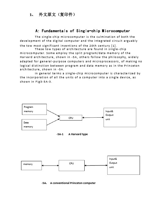
1、 外文原文(复印件)A: Fundamentals of Single-chip MicrocomputerT h e sin gle -ch ip mi c ro co m p u t e r is t h e cu lm in at io n of b ot h t h e d e ve lo p me nt of t h e d ig ita l co m p u t e r a n d t h e i nte g rated c ircu it a rgu ab l y t h e to w mo st s ign if i cant i nve nt i o n s of t h e 20t h c e nt u ry [1].T h ese to w t yp e s of arch ite ct u re are fo u n d in s in gle -ch ip m i cro co m p u te r. S o m e e mp l oy t h e sp l it p ro gra m /d at a m e m o r y of t h e H a r va rd arch ite ct u re , s h o wn in -5A , ot h e rs fo l lo w t h e p h i lo so p hy, wid e l y ad a p ted fo r ge n e ral -p u rp o se co m p u te rs an d m i cro p ro ce ss o rs , of m a kin g n o l o g i ca l d i st in ct i o n b et we e n p ro gra m an d d ata m e m o r y as in t h e P rin c eto n a rch ite ct u re , sh o wn in -5A.In ge n e ra l te r m s a s in g le -ch ip m ic ro co m p u t e r is ch a ra cte r ized b y t h e in co r p o rat io n of all t h e u n its of a co mp u te r into a s in gle d e vi ce , as s h o w n in F i g3-5A-3.-5A-1A Harvard type-5A. A conventional Princeton computerProgrammemory Datamemory CPU Input& Output unitmemoryCPU Input& Output unitResetInterruptsPowerFig3-5A-3. Principal features of a microcomputerRead only memory (ROM).RO M is u su a l l y fo r t h e p e r m an e nt , n o n -vo lat i le sto rage of an ap p l i cat io n s p ro g ram .M a ny m i c ro co m p u te rs a n d m i cro co nt ro l le rs are inte n d ed fo r h i gh -vo lu m e ap p l i cat io n s a n d h e n ce t h e e co n o m i cal man u fa c t u re of t h e d e vi ces re q u ires t h at t h e co nt e nts of t h e p ro gra m me mo r y b e co mm i ed p e r m a n e nt l y d u r in g t h e m a n u fa ct u re of c h ip s . C lea rl y, t h i s imp l ies a r i go ro u s ap p ro a ch to ROM co d e d e ve lo p m e nt s in ce ch an ges can n o t b e mad e af te r m an u fa ct u re .T h i s d e ve l o p m e nt p ro ces s m ay i nvo l ve e mu l at i o n u sin g a so p h ist icated d e ve lo p m e nt syste m wit h a h ard wa re e mu l at i o n capab i l it y as we ll as t h e u s e of p o we rf u l sof t war e to o l s.So m e m an u fa ct u re rs p ro vi d e ad d it i o n a l ROM o p t io n s b y in clu d in g in t h e i r ran ge d e v ic es w it h (o r inte n d ed fo r u s e wit h ) u se r p ro g ram m a b le m e mo r y. T h e s im p lest of t h e se i s u su a l l y d e v i ce wh i ch can o p e rat e in a m i cro p ro ce s so r mo d e b y u s in g s o m e of t h e in p u t /o u t p u t l in es as an ad d res s a n d d ata b u s fo r a cc es sin g exte rn a l m e m o r y. T h is t yp e o f d e vi ce can b e h ave f u n ct i o n al l y as t h e s in gle ch ip m i cro co m p u t e r f ro m wh i ch it i s d e ri ved a lb e it wit h re st r icted I/O an d a m o d if ied exte rn a l c ircu it. T h e u s e of t h e se RO M le ss d e vi ces i s co mmo n e ve n in p ro d u ct io n circu i ts wh e re t h e vo lu m e d o e s n ot ju st if y t h e d e ve lo p m e nt co sts of cu sto m o n -ch ip ROM [2];t h e re ca n st i ll b e a si gn if i cant sav in g in I/O an d o t h e r ch ip s co m pared to a External Timing components System clock Timer/ Counter Serial I/O Prarallel I/O RAM ROMCPUco nve nt io n al m i c ro p ro ces so r b ased circ u it. M o re exa ct re p l a ce m e nt fo rRO M d e v ice s can b e o b tain ed in t h e fo rm of va ria nts w it h 'p i g g y-b a c k'E P ROM(E rasab le p ro gramm ab le ROM )s o cket s o r d e v ice s w it h E P ROMin stead of ROM 。
电气外文文献-翻译

Circuit breaker断路器Compressed air circuit breaker is a mechanical switch equipment, can be i 空气压缩断路器是一种机械开关设备,能够在n normal and special conditions breaking current (such as short circuit cur 正常和特殊情况下开断电流(比如说短路电流)。
rent). For example, air circuit breaker, oil circuit breaker, interference circ 例如空气断路器、油断路器,干扰电路的导体uit conductor for the application of the safety and reliability of the circuit 干扰电路的导体因该安全可靠的应用于其中,breaker, current in arc from is usually divided into the following grades: a 电流断路器按灭弧远离通常被分为如下等级:ir switch circuit breaker, oil circuit breaker, less oil circuit breaker, compr 空气开关断路器、油断路器、少油断路器、压缩空essed air circuit breaker, a degaussing of isolating switch, six sulfur hexaf 气断路器、具有消磁性质的隔离开关、六氟luoride circuit breaker and vacuum breaker. Their parameters of voltage, 化硫断路器和真空断路器。
他们的参数有电压等级、current, insulation level of breaking capacity, instantaneous voltage off ti 开断容量的电流、绝缘等级开断时间的瞬时电压恢复和me of recovery and a bombing. Breaker plate usually include: 1 the maxi 轰炸时间。
(完整版)电气专业英文文献

An Expert System for Transformer Fault Diagnosis Using Dissolved Gas Analysis1. INTRODUCTIONThe power transformer is a major apparatus in a power system, and its correct functioning its vital to minimize system outages, many devices have evolved to monitor the serviceability of power transformers. These devices, such as, Buchholz relays or differential relays, respond only to a severe power failure requiring immediate removal of the transformer from service, in which case, outages are inevitable. Thus, preventive techniques for early detection faults to avoid outages would be valuable. In this way, analysis of the mixture of the faulty gases dissolved in insulation oil of power transformer has received worldwide recognition as an effective method for the detection of oncipient faults. Many researchers and electrical utilities have reported on their experience and developed interpretative criteria on the basis of DGA. However, criteria tend to vary from utility to utility. Therefore, transformer diagnosis is still in the heuristic stage. For this reason, knowledge-based programming is a suitable approach to implement in such a diagnostic problem.Based on the interpretation of DGA, a prototype of an expert system for diagnosis of suspected transformer faults and their maintenance procedures is proposed. The significant source in this knowledge base is the gas ratio method. Some limitations of this approach are overcome by incorporating the diagnostic procedure and the synthetic expertise method. Furthermore, data bases adopted from TPC'S gas records of transformers are incorporated into the expert system to increase the practical performance. Uncertainty of diagnosis is managed by using fuzzy set concepts. This expert system is constructed with rule based knowledge representation, since it can be expressed by experts. The expert system building tool,knowledge Engineering System(KES), is used in the development of the knowledge system because, it has excellent man-machine interface that provides suggestions. Moreover,its inference strategy is similar to the MYCIN. A famous rule-based expert system used for medical diagnosis. The uncertainty of human qualitative diagnostic expertise, e.g., key gasanalysis, and another quantitative imprecision, such as, norms threshold and gas ratio boundaries etc., are smoothed by appropriate fuzzy models. With the results of such implementation, different certainty factors will be assigned to the corresponding expertise variables. Both event-driven(forward chaining) and goal-driven (backward chaining) inferences are used in the inference engine to improve the inference efficiency. To demonstrate the feasibility of the proposed expert system, around hundreds of TPC historical gas records have been tested. It is found that more appropriate faulty types and maintenance suggestions can support the maintenance personals to increase the performance of transformer diagnosis.2. DEVELOPMENT OF DIAGNOSIS AND INTERPRETATIONLike many diagnostic problems, diagnosis of oil-immersed power transformer is a skilled task. A transformer may function well externally with monitors, while some incipient deterioration may occur internally to cause a fatal problem in the latter development. According to a Japanese experience, nearly 80% of all faults result from incipient deteriorations. Therefore, faults should be identified and avoided at the earliest possible stage by some predictive maintenance technique. DGA is one of the most popular techniques for this problem. Fault gases in transformers are generally produced by oil degradation and other insulating material, e.g., cellulose and paper. Theoretically, if an incipient or active fault is present, the individual dissolved gas concentration, gassing rate, total combustible gas(TCG) and cellulose degradation are all significantly increased. By using gas chromatography to analyse the gas dissolved in a transformer's insulating oil, it becomes feasible to judge the incipient fault types. This study is concerned with the following representative combustible gases; hydrogen(H2), methane(C2H2), ethane(C2H6), ethylene(C2H2) and carbon monoxide(C0).Many interpretative methods based on DGA to the nature of incipient deterioration have been reported. Even under normal transformer operational conditions, some of these gases may be formed inside. Thus, it is necessary to build concentration norms from a sufficiently large sampling to assess the statistics. TPC investigated gas data from power transformers to construct its criteria. The developedknowledge base in this paper is partially based on these data. On the hand, Dornerburg developed a method to judge different faults by rating pairs of concentrations of gases, e.g., CH/H, GH/C3H4, with approximately equal solubility and fusion coefficients. Rogers established mare comprehensive ratio codes to interpret the thermal fault types with theoretical thermodynamic assessments. This gas ratio method was promising because it eliminated the effect of oil volume and simplified the choice of units. Moreover, it systematically classified the diagnosis expertise in a table form. Table 1 displays the ratio method as proposed by Rogers. The dissolved gas may vary with the nature and severity of different faults. By analyzing the energy density of faults, it's possible to distinguish three basic fault processes:overheating(pyrolysis), corona(partial dischatge) and arcing discharge. Corona and arcing arise from electrical faults, while overheating is a thermal fault. Both types of faults my lead to deterioration, while damage from overheating is typically less than that from electrical stress. Infect, different gas trends lead to different faulty types, the key gas method is identified. For example, large amounts of CH and H are produced with minor arcing fault 4 quantities of CH 2aid C2H2 may bea symptom of an arcing fault.3.THE PROPOSED DIAGNOSTIC EXPERT SYSTEMThis study is aimed at developing a rule-based expert system to perform transformer diagnosis similar to a human expert. The details of system processing are described below.3.1 The Proposed Diagnostic MethodDiagnosis is a task that requires experience. It is unwise to determine an approach from only a few investigations. Therefore, this study uses the synthetic expertise method with the experienced procedure to assist the popular gas ratio method and complete practical performance.3.1.1 Experienced Diagnostic ProcedureThe overall procedure of routine maintenance for transformers is listed. The core of this procedure is based on the implementation of the DGA technique. The gas ratio method is the significant knowledge source. Some operational limitations of the gasratio method exist. The ratio table is unable to cover all possible cases. Minimum levels of gases must be present. The solid insulation involving CO and CO are handled separately and the gas ratio codes have been developed mainly from a free-breathing transformer. Other diagnostic expertise should be used to assist this method. Norms, synthetic expertise method and data base records have been incorporated to complete these limitations. The first step of this diagnostic procedure begins by asking DGA for an oil sample to be tested. More important relevant information about the transformer's condition, such as the voltage level, the preservative type, the on-line-tap-changer(OLTC) state, the operating period and degassed time must be known for further inference. Norms(criteria) Set up by TPC power transformers' gas characteristic data are then used to judge the transformers' condition. For the abnormal cases, the gas ratio method is used to diagnose transformer fault type. If different or unknown diagnosis results are found from these ratio methods, a further synthetic expertise method is adopted. After these procedures, different severity degrees are assigned to allow appropriate corresponding maintenance suggestions.3.1.2 Synthetic Expertise MethodThe ratio trend, norms threshold, key gas analysis and some expertise are considered as different evidences to confirm some special fault types. In other words, more significant evidences have been collected for some special fault type, better assessment of the transformer status is obtained.The ratio trend can be seen as a modification of the conventional gas ratio and key gas method.Obviously, the above gas trends should be incorporated with other evidences under the experienced procedure for practical use. Norms threshold, the gassing rate, the quantity of total combustible gas(TCG), the TPC maintenance expertise and the fuzzy set assignment are all important evidences considered in the synthetic diagnosis.Other expertise based on a transformer historical data base is also used to analyse the characteristics of a case transformer. Section 3.4 gives some details of these rules.3.2 Expert System StructureThe proposed diagnostic expert system is composed of components, working memory, a knowledge base, an inference engine and a man-machine interface. Working memory (global data base) contains the current data relevant to solve the present problem. In this study, most of the diagnostic variables stored in the data base are current gas concentration, some are from the user, others are retrieved from the transformer's historical data base. Note that the fuzzy set concept is incorporated to create fuzzy variables on the request of system reasoning. A knowledge relationship, which uses these facts, as the basis for decision making. The production rule used in this system is expressed in IF-THEN forms. A successful expert system depends on a high quality knowledge base. For this transformer diagnostic system, the knowledge base incorporates some popular interpretative methods of DGA, synthetic expertise method and heuristic maintenance rules. Section 3.4 will describe this knowledge base. Another special consideration in the expert system is its inference engine. The inference engine controls the strategies of reasoning and searching for appropriate knowledge. The reasoning strategy employs both forward chaining(data-driven) and backward chaining(goal-driven). Fuzzy rules, norms rules, gas ratio rules, synthetic expertise rules and some of the maintenance rules and some maintenance rules, use forward chaining.As for the searching strategy in KES, the depth first searching and short-circuit evaluation are adopted. The former can improve the search efficiency by properly arranging the location of significant rules in the inference procedures. The latter strategy only searches the key conditional statements in the antecedent that are responsible for establishing whether the entire rule is true or false. Taking the advantages of these two approaches in the building and structuring of a knowledge base improves inference efficiency significantly.As for man-machine interface. KES has an effective interface which is better than typical knowledge programming languages, such as, PROLOG or LISP. With the help of this interface, the capability of tracing, explaining and training in an expert system is greatly simplified.4.IMPLEMENTATION OF THE PROPOSED EXPERT SYSTEMAn expert system is developed based on the proposed interpretative rules and diagnostic procedures of the overall system. To demonstrate the feasibility of this expert system in diagnosis, the gas data supported by MTL of TPC have been tested. In Taiwan, the MTL of TPC performs the DGA and sends the results to all acting divisions relating to power transformers. In return, these acting divisions are requested to collect and supply their transformer oil samples periodically.After analysing oil samples, more than ten years' worthy gas records are collected and classified into three voltage level, 69KV, 16KV and 345KV. Thus, gas records for one transformer are composed of several groups of data. In the process of DGA interpretation, all of these data may be considered, but only the recent data which have significant effects on diagnosis are listed in the later demonstration. In MTL, all gas concentrations are expressed by pm in volume concentration. 100 pm is equal to 0.01 ml(gas)/100ml(oil).From the expertise of diagnosis, the normal state can be confirmed only by inspection of the transformer's norms level. In practice, most of the transformer oil samples are normal, and this can be inferred successfully on the early execution of this expert system. However, the Success of an expert system is mainly dependent on the capability of diagnosis for the transformers in question. In the implementation, many gas records which are in abnormal condition are chosen to test the Justification of this diagnostic system. A total of 101 transformer records have been executed and the results are summarized in Table 5. Among those implemented, three are listed and demonstrated.Shown in Table 5 are the results of 101 units of transformers in three types of remedy: normal, thermal fault and arc fault. After comparing them with the actual state and expert judgement, a summary of results was obtained. As previously stated, one unit of transformer may include many groups of gas data. In evaluation, we depicted some key groups in one unit to justify because some transformers may have different incipient faults during different operational stages. Some mistakes implemented from testing are caused by the remaining oil in the oil sampling container, unstable gas characteristics of the new degassing sample and some obscuregas types. If more information or new techniques support other uncertain membership functions, they can be added into the knowledge has to enlarge the the performance of this prototype expert system. Furthermore, the parameters described in table 2,3 and 4 are suitable for TPC power transformer. Different regions may be modified the maintenance personnel find more suitable system parameters.5.CONCLUSIONSA prototype expert system is developed on a personal computer using KES. It can diagnose the incipient faults of the suspected transformers and suggest proper maintenance actions. Fuzzy set concept is used to handle uncertain norms thresholds, gas ratio boundaries and key gas analysis. The synthetic method and diagnostic procedure are proposed to assist the situation which can not be handled properly by the gas ratio methods. Results from the implementation of the expert system shows that the expert system is a useful tool to assist human expert and maintenance engineers.The knowledge base of this expert system is incorporated within the popular interpretative method of DGA, synthetic expertise and heuristic maintenance rules. The data base supported by TPC MTL for about 10 year collection of transformer inspection data is also used to improve the interpretation of diagnosis. Through the development of the proposed expert system, the expertise of TPC MTL can be reserved. In addition, this work can be continued to expand the knowledge base by adding any new experience, measurement and analysis techniques.。
电气专业英文文献

Fire FightingAlong with the our country economic development rapid development, the lives of the people level unceasing enhancement, the city uses to be day by day anxious, urges the building to face the direction is developing. This kind of high level civil construction repair needed materials and the way also more hasten the diversification, and along with uses electricity the load and coal gas consumption quantity enlarging, proposed to the fire auto-alarm system design is higher, a stricter request. In order to guarantee the people life and property the security, the fire auto-alarm system design has become in the high level civil construction design one of most important design contents. Presently based on the author fire of auto-alarm system design overseeing work in the high level civil building experience, proposed in present national related standard and standard unclear true detail shallow opinion, by for the colleagues to discuss and to point out mistakes.First, design basisThe fire auto-alarm system design is a specialized very strong technology work, at the same time also has the very strong policy-type. Therefore, first should be clear about the following design basis:1st, must grasp the architectural design fire protection standard, the system design standard, the equipment manufacture standard, the installment construction approval standard and the administration laws and regulations and so on five big aspects fire laws and regulations, and in practical understanding present country related standard and standard positive word: "Must", "be supposed", "to be suitable", "may" and the reverse side word: "Strictly prohibits", "should not", "not have", "not to be suitable" the meaning. 2nd, must aim at high level civil building function, use and the protection object fire protection rank, earnestly carries out the present national related standard and the standard, earnestly treats the public security fire prevention surveillance department the examination and approval opinion.Second, fire auto-alarm system equipment establishmentFire detector establishmentOpens wide either the seal or the stair hall should alone divide the search coverage, and each 2 ~ 3 establish a fire detector.The first room (including guards against in front of smoke stair hall in front of room, fire elevator room, fire elevator with guards against the front room which smoke stair hall comes in handy) and the aisle should distinguish alone to divide the search coverage, specially front the room and the lift well, the scattered stair hall and the aisle are interlinked, has time the fire haze to be easier to gather or to flow, is the personnel disperses which saves goal with the fire prevention, therefore should install the fire detector. Regarding common elevator in front of room although is not the personnel disperses , butthis front room and the lift well are interlinked, has time the fire haze to be also easy to gather or to flow, suitably alone divides the search coverage and installs the fire detector.The electric cable shaft therefore is easy to form pulls out the smoke inflammation the channel; Has when the fire the fire intensity not easily extends along the electric cable burns, for this, "the high level civil construction design fire protection standard" and "the civil construction electricity design standard" separately proposes the detailed specific stipulation in the construction and in the electric wire or on the electric cable shaping. But considered implements specifically the difficulty and the present situation, the electric cable shaft installs the fire detector is extremely essential, and coordinates the shaft the fire protection separation request, each 2 ~ 3 or each level installs.The elevator machine room should install the fire detector, its elevator is the important vertical transportation vehicle; Its two elevator machine room has has the fire risk; Its three lift well existence essential opens the hole, like the level gate opens between the hole, the air vent, the between permanence opens the hole with the elevator machine room or the pulley and so on; Its four when has the fire, the lift well often becomes the fire intensity spread the channel, is easy to threaten the elevator machine room the facility. Therefore, the elevator machine room establishes the fire detector is necessary, crown of also suitable establishment fire detector lift well.2nd, the manual fire reports to the police the button establishment (Including guards against in front of smoke stair hall in view of various floors front room in front of room, fire elevator room, fire elevator with guards against which smoke stair hall to come in handy the front room) is has when the fire the personnel to disperse which saves goal with fire prevention, should report to the police the button first choice spot as the establishment manual fire. In addition, the room also should establish the manual fire to the common elevator in front of to report to the police the button.In the public active place (including hall, hall, dining room, multi-purpose hall and so on) and the main thoroughfare and so on place, the personnel very is all centralized, and mainly disperses the channel. Therefore should report to the police the button in these public active places main access establishment manual fires; The manual fire establishes which in the main thoroughfare reports to the police the button to guarantee "to a manual fire which most is close to reports to the police the button distance from a fire protection district any position not to be supposed to be bigger than 30 meters".3rd, the fire emergency broadcasts the speaker the establishmentThe aisle, the hall, the dining room and so on the public place personnel very are all centralized, and mainly disperses the channel. Therefore should press in these public places "to a recent speaker distance is not bigger than 25 meters from a fire protection district any spot" and "in the aisle last should not be bigger than 12.5 meters the speaker to the aisle terminal distance" the establishment fire emergency to broadcast the speaker; Next also should establish the fire in the public bathroom place emergency to broadcast the speaker.The first room (including guards against in front of smoke stair hall in front of room, fire elevator room, fire elevator with guards against which smoke stair hall to come in handy the front room) is has when the fire the personnel to disperse which saves goal with fire prevention, also has the fire door separation and the sounds of people is confused and noisy, therefore should establish the fire emergency to broadcast the speaker. In front of the common elevator the room also should establish the fire emergency to broadcast the speaker. Disperses the stair hall also is has when the fire the personnel to disperse which saves goal with the fire prevention, also the sounds of people are confused and noisy, therefore should establish the fire emergency to broadcast the speaker, by favors the fire emergency broadcast to disperse the instruction.4th, fire alarm installment establishmentThe establishment fire emergency broadcast fire auto-alarm system, the author thought also should install the fire alarm installment, but its control procedure should be: The alarm apparatus should confirm after the fire, uses manual or the automatic control mode unification to the fire correlation region transmission warning, stops the alarm apparatus work in the stipulation time, the rapid linkage fire emergency broadcast and broadcasts to the people disperses the instruction.The fire alarm installment establishment position, the author thought should report to the police the button position with the manual fire to be same, its wall surface installment should for be apart from the ground 1.8 meters highly5th, fire special use telephone establishmentInstalls the fire special use telephone extension telephone, should be located the engine room which related also some people is on duty frequently with the fire linkage control (including fire water plant, spare electricity generation engine room, matches substation, mainly ventilates with air conditioning engine room, discharges fume engine room, fire prevention elevator machine room and other), the fire fighting control system operates the equipment place or the control room, the fire duty officers observation room, the security manages spot and so on public room. Sedan of theater box the fire elevatorand in the ordinary elevator all should suppose the special use telephone, requests the elevator machine room and the elevator sedan theater box, the elevator machine room and the fire control room, the elevator sedan theater box and the fire control room and so on three compositions is reliable to speaks the correspondence telephone system. Usually in fire control room; The establishment elevator monitoring demonstration plate (including position indicator, direction indicating lamp, to speaks correspondence telephone, trouble lamp and so on), in order to carries on the necessity to the elevator running status which in the surveillance and the emergency case controls.Is equipped with the manual fire to report to the police position and so on button, fire hydrant button also should install the fire special use telephone receptacle.Third, fire linkage control1st, the fire linkage control should include the control fire pump to open, to stop, also should demonstrate opens pumps the button the position and the fire pump work and the malfunction. When the fire hydrant is equipped with the fire hydrant button, its electric installation work spot also should demonstrate the fire pump the working mode active status (namely establishment fire pump work indicating lamp).2nd, the fire linkage control should include the control spraying of water and the water atomization fire fighting system opens, stops, also should demonstrate the fire pump the work and the malfunction and the fluent display, reports to the police the valve, the safety signal valve working mode active status. In addition, to the basin, the water tank water level also should carry on the demonstration monitor; In order to prevent the overhaul signal valve is shut down, the author thought should use the belt electric signal the control signal valve by to demonstrate it opens the condition.3rd, the fire linkage control other controls and the demonstration function, should carry out the present national related standard and the standard specific stipulation.Fourth, fire auto-alarm system wiringIn order to prevent the fire occurs when the fire control, the correspondence and the warning line severance, causes the fire fighting work to be unable to carry on, creates the bigger economic loss; Also for the suppression electronmagetic interference (for example transformer, electric motor, electric cable and so on) the influence which produces to the fire auto-alarm system. The fire auto-alarm system transmission line and the fire control, the correspondence and the warning line should use the being flame-resistant electric cable, and should use the metal tube or the enclosed metal trunking protection. The fire manual positive governing installment line should use the fireproof electric cable, its electric cable also should use the metal tube or theenclosed metal trunking protection. Uses Ming Fushi, should takes the fire protection protective measures on the metal tube or the enclosed metal trunking.Fifth, concluding remarkThe author rests on the concrete project to implement the experience, elaborated the design basis, fire auto-alarm design actual problem and so on system equipment establishment, fire linkage control and its wiring pulls out some shallow opinions, its goal is enhances the fire auto-alarm system the design quality, discovered early and the notification fire, prevented and reduces the fire to harm, by protects the person and the property safety.。
建筑电气外文文献

提高个人的生活质量,通过他们的智能家居该项目的假设是:可以增加一个人的生活质量的“智能技术”集成到他们的家庭环境。
这个假设是非常广泛的,因此,研究人员将调查它考虑到多方面的,潜在的过度研磨,分节的人口。
特别是,该项目将重点放在与卫生保健需求的环节,因为它认为,这些子章节将获得最大的受益于这种增强的方法住房。
两个研究问题流从这一假说:什么是保健,可以改善通过“智能住宅”的问题,什么是技术问题需要解决,让“智能住宅”建造?虽然存在少量的措施,在加拿大境外,据称这方面的调查,没有这方面的全球视野。
工作往往是在小围的各个部分是如何有助于实现更大的目标只有有限的想法。
这个项目有一个非常强烈的责任感,并认为,如果没有这一全球性的方向,其他措施将失败,以解决各部分的重要问题,而且正确的全局方向的总和的部分会产生更大的回报比的各个组成部分。
这个新的领域与业务流程工程领域,有许多相似之处,很多产品失败的原因只考虑一个子集的问题,通常是技术的子集。
成功的项目和实施才开始启动,当人们开始认识到,一个全面的方法是至关重要的。
这种整体性的要求也适用于领域的“聪明屋”,如果我们真的希望它有利益于社区,而不仅仅是技术的兴趣。
话虽如此,下面列出的大部分工作是非常重要的,在其个人的主题包含了大量新奇的。
医疗保健和保障性住房:至目前为止,很少有人协调,研究如何“聪明屋”的技术可以帮助体弱的老人留在家里,或降低成本所经历的非正式照顾者。
因此,建议研究的目的是确定帮助老年人保持自己的独立性和帮助照顾者维持他们的爱心活动中的各种住宅技术的实用性。
整体设计的研究是集中在两个群体的老年人。
首先是老人出院急性护理环境的潜在能力下降,保持独立。
一个例子是有髋关节置换手术的老年人。
本集团可能会受益于技术,这将有助于他们成为适应他们的行动不便。
第二个是老年人有慢性健康问题,如老年痴呆症和接受援助的非正式护理员的生活在距离。
关心的高级生活的距离是非正式照顾者在照顾者的职业倦怠的高风险。
- 1、下载文档前请自行甄别文档内容的完整性,平台不提供额外的编辑、内容补充、找答案等附加服务。
- 2、"仅部分预览"的文档,不可在线预览部分如存在完整性等问题,可反馈申请退款(可完整预览的文档不适用该条件!)。
- 3、如文档侵犯您的权益,请联系客服反馈,我们会尽快为您处理(人工客服工作时间:9:00-18:30)。
建筑电气外文文献提高个人的生活质量,通过他们的智能家居该项U的假设是:可以增加一个人的生活质量的“智能技术”集成到他们的家庭环境。
这个假设是非常广泛的,因此,研究人员将调查它考虑到多方面的,潜在的过度研磨,分节的人口。
特别是,该项U将磴点放在与卫生保健需求的环节,因为它认为,这些子章节将获得最大的受益于这种增强的方法住房。
两个研究问题流从这一假说:什么是保健,可以改善通过“智能住宅”的问题,什么是技术问题需要解决,让“智能住宅”建造,虽然存在少量的措施,在加拿大境外,据称这方面的调查,没有这方面的全球视野。
工作往往是在小范W内的各个部分是如何有助于实现更大的U标只有有限的想法。
这个项U有一个非常强烈的责任感,并认为,如果没有这一全球性的方向,其他措施将失败,以解决各部分的重要问题,而且正确的全局方向的总和的部分会产生更大的回报比的各个组成部分。
这个新的领域与业务流程工程领域,有许多相似之处,很多产品失败的原因只考虑一个子集的问题, 通常是技术的子集。
成功的项U和实施才开始启动,当人们开始认识到,一个全面的方法是至关重要的。
这种整体性的要求也适用于领域的“聪明屋”,如果我们真的希望它有利益于社区,而不仅仅是技术的兴趣。
话虽如此,下面列出的大部分工作是非常重要的,在其个人的主题包含了大量新奇的。
医疗保健和保障性住房:至UMJ为止,很少有人协调,研究如何“聪明屋”的技术可以帮助体弱的老人留在家里,或降低成本所经历的非正式照顾者。
因此,建议研究的U的是确定帮助老年人保持自己的独立性和帮助照顾者维持他们的爱心活动中的各种住宅技术的实用性。
整体设计的研究是集中在两个群体的老年人。
首先是老人出院急性护理环境的潜在能力下降,保持独立。
一个例子是有髓关节置换手术的老年人。
本集团可能会受益于技术,这将有助于他们成为适应他们的行动不便。
第二个是老年人有慢性健康问题,如老年痴呆症和接受援助的非正式护理员的生活在距离。
关心的高级生活的距离是非正式照顾者在照顾者的职业倦怠的高风险。
监测的关心,高级健康和安全是通过这样照顾者的重要任务之一。
如地面传感器和访问控制来确保安全的入侵者或指示私奔与老年痴呆症的高级设备,可以减少护理员的时间花在上下班的高级对于这两种样品,试验将包括长时间内的“聪明屋”的居住。
急性护理医院出院急性护理的老年人。
这些老年人照顾的非正式照顾者的距离可以招募老年痴呆症诊断诊所或通过请求照顾者喘息的机会。
数量有限的临床和医疗服务研究已进行了复杂的健康问题,在老年人中控制的环境中,如为代表的“智能家居”。
例如,它被称为夜视老人是可怜的,但很少有有关醒来后照明或夜间活动的最佳水平。
跌倒是老年人的一个主要问题,它导致受伤,残疾和额外的医疗费用。
对于那些痴呆的疾病,安全的关键问题是在性能日常生活活动(ADL)o至关a要的是,我们能够监控病人会下降,在ADL。
患者和照顾者的活动进行监测和数据将被收集在下列1W况下。
项U将集中于亚人群,以收集科学数据,其条件和技术的影响,在他们的生活方式。
例如:稳定的慢性中风后的残疾和他们的照顾者的人:研究优化模型,对于此类患者 (这些患者可能有疏忽,偏瘫,失语和判断问题)的各种传感器的类型和位置,在行走运动的发展模式研究,使用轮椅或拐杖上各种不同类型的地板材料,研究照顾者支持监测频率和位置的瀑布;智能家电,以评估的价值为中风病人及照顾者对信息进行评佔,并通过电子医疗技术;通信技术促进远程家庭护理评估技术接口,用于远程家庭护理的工作人员和客户的各种照明部分的房子,以评估最有效的方法,修改或开发新技术,以提高舒适性和便利性中风患者和照顾者,以评估值的监控系统,协助照顾者。
人与阿尔茨海默氏病和他们的照顾者:通过智能房子陌生的环境的影响,以评佔他们的能力,以进行自我保健和没有提示的宿况下,评估他们的能力,以使用不熟悉的设备中的智能房子,以评估和监测人与阿尔茨海默氏症的运动方式,评估和监控跌倒或徘徊;评估的类型和型号的传感器,以监测患者的效果进行评估,墙面的颜色为病人和照顾者适当的照明,以评估值。
普适计算技术:无处不在的计算基础设施被视为在家里的“智能”的骨干。
在与无处不在的计算系统,这个系统的主要组成部分是:阵列传感器,通信基础设施和软件控制(基于软件代理)基础设施。
同样,它被认为是必要的,从整体上研究这个话题。
传感器设计:在这里研究的重点将是发展的(微型)传感器和传感器阵列使用智能材料,如:圧电材料,磁致伸缩材料和形状记忆合金(形状记忆合金)。
特别是,形状记忆合金是一类智能材料,是有吸引力的用于感测和致动的应用,主要是因为它们的异常高的工作输出/体积比相比,智能材料的形状记忆合金进行适当的机械和热负荷的制度时,经过固一固相变,导致在一个宏观的尺寸和形状的变化,这种变化是通过反转的热机械加载收回,并且被称为一个单向形状记忆的效果。
山于这种材料的功能,形状记忆合金可以用来作为一个传感器和致动器。
一个非常最近的发展是努力,将形状记忆合金在微机电系统(MEMS)等,这些材料可以使用作为微传感器和致动器的组成部分。
MEMS领域的活动,其中一些技术已经足够成熟,可能的商业应用出现。
一些例子是微化学分析仪,湿度和圧力传感器,MEMS流量控制,合成射流激励器和光学MEMS (下一代互联网)。
将形状记忆合金在MEMS研究界是一个相对较新的努力,据我们所知,只有一组(格雷格?卡门教授,机械工程,美国加州大学洛杉矶分校)已经成功地演示了动态特性,基于SMA- MEMSo在这里,重点将是利用传感和驱动功能的智能材料设计和制造有用的和经济上可行的微型传感器和执行器。
通讯:“智能屋”的建设和使用提供了广泛的机会,以家庭为基础的无线和有线通信服务来分析和验证。
虽然其中一些已经广泛地探讨,许多问题已经得到很少或根本没有注意。
建议探讨以下问题:测量的信道统计在住宅环境:室内无线信道统计的知识是至关重要的,使高效率的发射器和接收器的设计,以及确定适当水平的信号功率,数据传输速率,调制技术,差错控制码的的无线链路。
干扰,信道失真, 频谱限制,产生的结果为残疾人(轮椅的设备,四站,监控设备等)特别感兴趣。
增强室内无线通信天线的设计,分析和验证。
室内无线通信的需要结构紧凑, 坚固耐用的天线。
新的天线设计,优化所需的数据传输速率,工作频率和空间的要求,可以考虑。
最近已经商业化的验证和分析的室内无线网络:无线网络标准,家庭自动化操作。
整合这些系统的智能家居中的一个或多个提供的机会,以验证这些系统的操作,检查其局限性,并确定是否过度设计标准,以满足一般的需求。
有效的通信线路计划确定为“智能家居”:存在有线和无线基础设施的性能/成本权衡。
不同的无线网络配置的测量和分析,以便确定适当的网络设计。
代价较大规模的通信系统:室内无线网络的室内通信系统的协调是当地的住所附近。
存在更广泛的大规模网络,如蜂窝式电话网络,固定无线网络,和基于卫星的通信网络。
保健监测的U的,这些服务之间的相容性的可行性和实用性,老年痴呆症患者的跟踪,等需要考虑。
软件代理和他们的工程:嵌入式代理可以被认为是相当于提供一个友好的专家与产品。
嵌入式代理智能建筑带来许多的挑战,无论是在水平的设il•方法以及详细的实施。
在这方面的项U将包括:人类居住环境的大型智能体系统的架构:住宅长期护理的环境中成功部署代理技术需要新的架构,这些系统的设计。
一个合适的架构应该是简单而灵活地提供实时有效的代理操作。
同时,它应该是分层的刚性, 以允许执行的规则和限制,确保的居民建筑系统的安全。
必须解决这些矛盾的要求,通过设计一个新的架构,将系统中的所有代理共学。
强大的决策和控制结构,学习代理:实现终身学习的能力,代理商需要配备强大的机制,学习和适应。
隔离使用一些传统的学习系统是不可能的,因为这些药物的髙预期寿命。
我们要发展的儿个学习和表现方法,在一个新兴的时尚相结合的混合式学习系统。
这样的系统会采用不同的方法,根据自己的成熟度和量的变化,以适应新的1W 况或学习新的行为。
为了应付高层次的不确定性从这些来源不可预测的人类用户的互动,强大的行为将被设计和实施能够处理不同类型的不确定性(如概率和模糊不确定性)采用了先进的技术,感觉和数据基于计算智能技术的融合和推理机制。
自动建模现实世界的对象,包括个别住户:这个问题在这里是:“定位和提取” 的个性和习惯一个人的代表性是至关重要的信息;系统是“遵循和采用”个人的1W 绪和行为的发展。
基于数据挖掘和进化的技术,解决方案,将利用:(1)聚类方法, 分类的树木和关联发现重要的不同属性之间的关系属于个人的各种功能的分类和分区技术,这是一个基本要素在寻找一个人的行为模式,和(2)神经模糊和以规则为基础的系统,用于个人的特性发展模式的学习和适应能力,这是必要的估计和预测的潜在活动和远期规划。
调査的框架普适il•算的特点:考虑分布式和基于互联网的系统,这也许是最常见的,无处不在的计算,最大的影响是不特定的软件工程过程, 但是从现有的软件框架或工具包“,这让在这些领域的许多系统的快速建设和部署。
因此,它提出的“聪明屋”无处不在的计算基础设施的建设也应利用作为一个软件工程的研究。
研究人员将首先参观一些真正的无处不在的il•算系统中存在的今天,试图建立一个初始图片的功能的框架。
(这种方法有明显的相似之处伽玛的方法,约翰逊和Vlissides部署他们的开创性工作,“设计模式”。
不幸的是,在他们的工作相比,这里的样本量将是非常小的,因此,额外的工作将需要可靠的答案。
)初步框架,随后将作为智能家居的软件系统的基础上。
毫无疑问,这个初步框架将大幅进化的系统建设过程中,无处不在的计算环境的要求展开。
它被认为是一个真正有用的和可靠的神器,体系建设等密切参与是一个必要的组成部分。
施工阶段的末尾,预计将产生一个稳定的框架,它可以表明,大量的基本特征(或图案) 已发现的普适计算。
无处不在的计算问题的确认和验证(V, V):希望调査确认和验证(V,V)普适计算的问题,房子会提供一个测试床。
房子将被用作评估车辆,以确定哪些V,V技术, 工具或方法,如果没有,在此环境中是有用的。
此外,计划提供给全世界的研究人员使用这种车辆的增加,使这个试验设施。
长远来看,预计这种基础设施所提供的设施,将演变成一个国际公认的“标杆”的网站V,V活动中无处不在的计算。
其他技术领域:该项U还计划调查了一些其他领域,如照明系统,安防系统,加热,通风和空调等,例如,能源效率方面,该项UUiiu预计承担的两项研究:测定绝缘白叶窗的效果:外部绝缘白叶窗随着时间的推移是无效的,因为密封问题。
室内白•叶窗是优越的,可以用来帮助减少热量的损失。
然而,它们的移动和定位,需要适当的控制,以防止山于热冲击的窗口破损。