一个简单的单臂路由的配置的过程
华为单臂路由配置实例
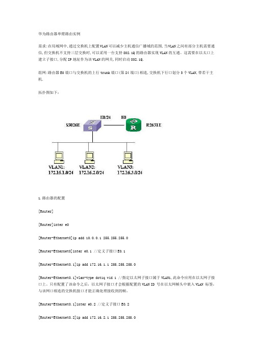
华为路由器单臂路由实例需求:在局域网中,通过交换机上配置VLAN可以减少主机通信广播域的范围,当VLAN之间有部分主机需要通信,但交换机不支持三层交换时,可以采用一台支持802.1Q的路由器实现VLAN的互通。
这需要在以太口上建立子接口,分配IP地址作为该VLAN的网关,同时启动802.1Q.组网:路由器E0端口与交换机的上行trunk端口(第24端口)相连,交换机下行口划分3个VLAN,带若干主机.拓扑图如下:1.路由器的配置[Router][Router]inter e0[Router-Ethernet0]ip add 10.0.0.1 255.255.255.0[Router-Ethernet0]inter e0.1 //定义子接口E0.1[Router-Ethernet0.1]ip add 172.16.1.1 255.255.255.0[Router-Ethernet0.1]vlan-type dot1q vid 1 //指定以太网子接口属于VLAN1,此命令应用在以太网子接口上。
只有配置了该命令之后,以太网子接口才会根据配置的VLAN ID 号在以太网帧头中嵌入VLAN 标签,与该网口相连的交换机接口才能正确处理接收到的帧。
[Router-Ethernet0.1]inter e0.2 //定义子接口E0.2[Router-Ethernet0.2]ip add 172.16.2.1 255.255.255.0[Router-Ethernet0.2]vlan-type dot1q vid 2 //指定以太网子接口属于VLAN2[Router-Ethernet0.2]inter e0.3 //定义子接口E0.3[Router-Ethernet0.3]ip add 172.16.3.1 255.255.255.0[Router-Ethernet0.3]vlan-type dot1q vid 3 //指定以太网子接口属于VLAN3[Router-Ethernet0.3]inter e0[Router-Ethernet0]undo shut% Interface Ethernet0 is up[Router-Ethernet0] //用网线将E0端口连到S3026第24端口%19:46:32: Interface Ethernet0 changed state to UP%19:46:32: Line protocol ip on interface Ethernet0, changed state to UP%19:46:32: Line protocol ip on interface Ethernet0.1, changed state to UP%19:46:32: Line protocol ip on interface Ethernet0.2, changed state to UP%19:46:32: Line protocol ip on interface Ethernet0.3, changed state to UP2.交换机的配置sysEnter system view , return user view with Ctrl+Z.[Quidway]vlan 1[Quidway-vlan1]vlan 2[Quidway-vlan2]port ethernet 0/17 to eth 0/19 eth 0/22 //将第17至19端口,和第22端口加入VLAN2 [Quidway-vlan2]vlan 3[Quidway-vlan3]port eth 0/21 //将第21端口加入VLAN2[Quidway-vlan3]inter e0/24[Quidway-Ethernet0/24]port link-type trunk //将第24端口设为trunk口[Quidway-Ethernet0/24]port trunk permit vlan all//允许所有VLAN流量通过Please wait........................................... Done. [Quidway-Ethernet0/24]dis port trunk //检验TRUNK口配置Now, the following trunking ports exist:Ethernet0/24[Quidway-Ethernet0/24]dis vlan 2 //检验VLAN2的配置VLAN ID: 2VLAN Type: staticRoute Interface: not configuredDescription: VLAN 0002Tagged Ports:Ethernet0/24Untagged Ports:Ethernet0/17 Ethernet0/18 Ethernet0/19 Ethernet0/22[Quidway-Ethernet0/24]dis vlan 3 //检验VLAN3的配置VLAN ID: 3VLAN Type: staticRoute Interface: not configuredDescription: VLAN 0003Tagged Ports:Ethernet0/24Untagged Ports:Ethernet0/213.在工作站上检查网络是否连通。
单臂路由的基本配置

单臂路由的基本配置计算机网络实验报告实验六单臂路由的基本配置一、实验目的.(1)熟悉VLAN的配置(2)熟悉路由器子接口的配置(3)熟悉子接口的封装(4)熟悉子网的划分二、实验环境.1.拓扑图:三、实验步骤.配置步骤1.主机配置IP地址信息。
PC1.IP地址:192.168.0.2 子网掩码:255.255.255.224 默认网关:192.168.0.1PC2.IP地址:192.168.0.34 子网掩码:255.255.255.224 默认网关:192.168.0.33 PC3. IP地址:192.168.0.66 子网掩码:255.255.255.224 默认网关:192.168.0.65 PC4. IP地址:192.168.0.100 子网掩码:255.255.255.224 默认网关:192.168.0.99 PC5. IP地址:192.168.0.132 子网掩码:255.255.255.224 默认网关:192.168.0.131 PC6. IP地址:192.168.0.164 子网掩码:255.255.255.224 默认网关:192.168.0.1632.路由器子接口的配置Router(config-subif)#int f0/0.1 Router(config-subif)#en dot1q 1Router(config-subif)#ip add 192.168.0.1 255.255.255.224Router(config-subif)#int f0/0.2Router(config-subif)#en dot1q 2Router(config-subif)#ip add 192.168.0.33 255.255.255.224Router(config-subif)#int f0/0.3 Router(config-subif)#en dot1q 3Router(config-subif)#ip add 192.168.0.65 255.255.255.224Router(config-subif)#int f0/0.4 Router(config-subif)#en dot1q 4Router(config-subif)#ip add 192.168.0.99 255.255.255.224Router(config-subif)#int f0/0.5 Router(config-subif)#en dot1q 5Router(config-subif)#ip add 192.168.0.131 255.255.255.224Router(config-subif)#int f0/0.6 Router(config-subif)#en dot1q 6Router(config-subif)#ip add 192.168.0.163 255.255.255.224Router(config)#int f0/0 Router(config-if)#no shut3.交换机VLAN配置 Switch(config)#VLAN 1 Switch(config-vlan)#VLAN 2Switch(config-vlan)#VLAN 3 Switch(config-vlan)#VLAN 4 Switch(config-vlan)#VLAN 5 Switch(config-vlan)#VLAN 6Switch(config)#INT F0/1Switch(config-if)#SWITCHPORT MODE ACCESS Switch(config-if)#SWITCHPORT ACCESS VLAN 1Switch(config)#INT F0/2Switch(config-if)#SWITCHPORT MODE ACCESS Switch(config-if)#SWITCHPORT ACCESS VLAN 2Switch(config)#INT F0/3Switch(config-if)#SWITCHPORT MODE ACCESS Switch(config-if)#SWITCHPORT ACCESS VLAN 3Switch(config)#INT F0/4Switch(config-if)#SWITCHPORT MODE ACCESS Switch(config-if)#SWITCHPORT ACCESS VLAN 4Switch(config)#INT F0/5Switch(config-if)#SWITCHPORT MODE ACCESS Switch(config-if)#SWITCHPORT ACCESS VLAN 5Switch(config)#INT F0/6Switch(config-if)#SWITCHPORT MODE ACCESS Switch(config-if)#SWITCHPORT ACCESS VLAN 64.交换机干线接口配置 Switch(config)#INT F0/7Switch(config-if)#SWITCHPORT MODE TRUNK5.测试PC2到PC3的连通性,并在1处抓取来回数据,对数据进行详细分析。
如何配置华为单臂路由
如何配置华为单臂路由推荐文章华为5700交换机dhcp怎么配置热度:华为usg防火墙基本配置命令有哪些热度:华为单臂路由的配置方法步骤图热度:华为交换机ospf的配置方法步骤热度:华为交换机配置的命令有哪些热度:华为的产品主要涉及通信网络中的交换网络、传输网络、无线及有线固定接入网络和数据通信网络及无线终端产品,那么你知道如何配置华为单臂路由吗?下面是店铺整理的一些关于如何配置华为单臂路由的相关资料,供你参考。
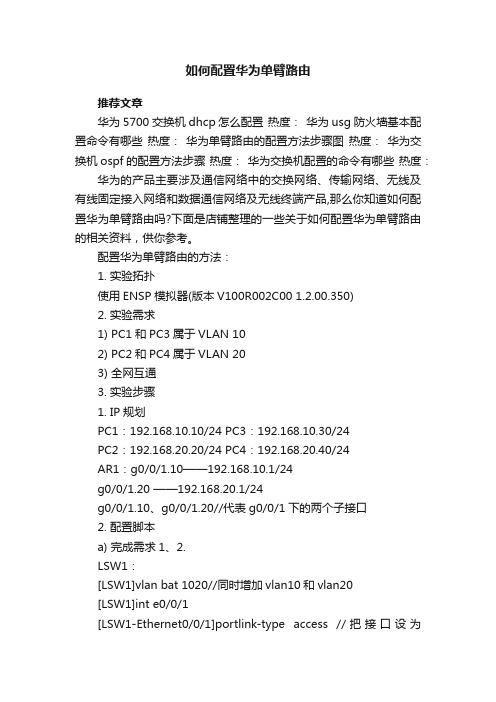
配置华为单臂路由的方法:1. 实验拓扑使用ENSP模拟器(版本V100R002C00 1.2.00.350)2. 实验需求1) PC1和PC3属于VLAN 102) PC2和PC4属于VLAN 203) 全网互通3. 实验步骤1. IP规划PC1:192.168.10.10/24 PC3:192.168.10.30/24PC2:192.168.20.20/24 PC4:192.168.20.40/24AR1:g0/0/1.10——192.168.10.1/24g0/0/1.20 ——192.168.20.1/24g0/0/1.10、g0/0/1.20//代表g0/0/1下的两个子接口2. 配置脚本a) 完成需求1、2.LSW1:[LSW1]vlan bat 1020//同时增加vlan10和vlan20[LSW1]int e0/0/1[LSW1-Ethernet0/0/1]portlink-type access //把接口设为access口[LSW1-Ethernet0/0/1]portdefault vlan 10 //默认此接口允许vlan10通过[LSW1-Ethernet0/0/1]inte0/0/2[LSW1-Ethernet0/0/1]portlink-type access[LSW1-Ethernet0/0/2]portdefault vlan 20LSW2:[LSW2]vlan bat 10 20[LSW2]inte0/0/3[LSW2-Ethernet0/0/3]portlink-type access[LSW2-Ethernet0/0/3]portdefault vlan 10[LSW2-Ethernet0/0/3]inte0/0/4[LSW2-Ethernet0/0/4]portlink-type access[LSW2-Ethernet0/0/4]portdefault vlan 20b) 将两台交换机之间设为trunk(中继)口LSW1:[LSW1]int g0/0/2[LSW1-GigabitEthernet0/0/2]portlink-type trunk //把这个接口设为Trunk口[LSW1-GigabitEthernet0/0/2]porttrunk allow-pass vlan 10 20 //让这个接口允许vlan10和vlan20通过。
局域网环境单臂路由的配置
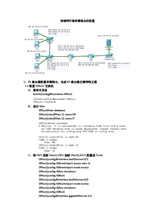
局域网环境单臂路由的配置1、R1路由器配置单臂路由,完成R1路由器左侧网络互通1.1配置Office1交换机A、重命名设备Switch(config)#hostname Office1B、划分VlanOffice1#vlan databaseOffice1(vlan)#Vlan 11 name HROffice1(vlan)#Vlan 12 name ITC、将F0/1划给Vlan11,F0/2划给Vlan12,G1/1配置成TrunkOffice1(config)#interface fastEthernet 0/1Office1(config-if)#switchport access vlan 11Office1(config-if)#switchport mode accessOffice1(config-if)#no shutdownOffice1(config-if)#exitOffice1(config)#interface fastEthernet 0/2Office1(config-if)#switchport mode accessOffice1(config-if)#no shutdownOffice1(config-if)#exitOffice1(config)#interface gigabitEthernet 1/1Office1(config-if)#switchport mode trunkOffice1(config-if)#no shutdown1.2配置Office2交换机A、重命名设备Switch(config)#hostname Office2B、划分VlanOffice2#vlan databaseOffice2(vlan)#Vlan 11 name HROffice2(vlan)#Vlan 12 name ITC、将F0/1划给Vlan11,F0/2划给Vlan12,G1/1、G1/2配置成TrunkOffice2(config)#interface fastEthernet 0/1Office2(config-if)#switchport access vlan 11Office2(config-if)#switchport mode accessOffice2(config-if)#no shutdownOffice2(config-if)#exitOffice2(config)#interface fastEthernet 0/2Office2(config-if)#switchport access vlan 12Office2(config-if)#switchport mode accessOffice2(config-if)#no shutdownOffice2(config-if)#exitOffice2(config)#interface range gigabitEthernet 1/1-2Office2(config-if-range)#switchport mode trunkOffice2(config-if-range)#no shutdown1.3R1路由器配置单臂路由,完成R1路由器左侧网络互通A、重命名设备Router(config)#hostname R1B、开启F0/1接口,并配置子接口Router(config)#interface fastEthernet 0/1Router(config-if)#no shutdownRouter(config-if)#exitRouter(config)#interface fastEthernet 0/1.1Router(config-subif)#encapsulation dot1Q 11Router(config-subif)#ip address 172.10.11.1 255.255.255.0Router(config-subif)#exitRouter(config)#interface fastEthernet 0/1.2Router(config-subif)#encapsulation dot1Q 12Router(config-subif)#ip address 172.10.12.1 255.255.255.0Router(config-subif)#exitC、任意PC进行测试互通。
openwrt单臂路由设置方法(一)

openwrt单臂路由设置方法(一)OpenWrt单臂路由设置什么是单臂路由?单臂路由(One-armed routing)是一种网络设置方式,其中路由器只有一个网络接口与局域网(LAN)相连,并且使用网络地址转换(NAT)来连接到互联网。
为什么要使用单臂路由?使用单臂路由可以解决多个子网位于同一个网络接口的问题。
这样可以方便地管理和监控网络流量,增强网络安全性和性能。
OpenWrt支持单臂路由的设置方法方法一:使用接口的自动设置(默认方法)1.在OpenWrt的界面上,点击“网络”>“接口”。
2.点击“添加新接口”按钮。
3.设置接口名称,并选择与之关联的物理接口。
4.在IPv4地址/子网掩码字段中输入相应的IP地址和子网掩码。
5.点击“保存&应用”。
方法二:使用命令行进行手动设置1.连接到OpenWrt路由器的SSH终端。
2.使用以下命令查看当前网络接口列表:ifconfig。
3.找到要用作单臂路由的接口,记录其接口名,如“eth0”。
4.使用以下命令创建新的网络接口:uci setnetwork.eth0=interface(其中“eth0”为实际接口名)。
5.使用以下命令配置接口参数:–uci set network.eth0.proto=dhcp:使用DHCP自动获取IP地址。
–uci set network.eth0.ifname=eth0:指定物理接口。
–uci set network.eth0.type=bridge:设置为桥接模式。
6.使用以下命令保存配置并应用更改:uci commit network。
7.重启网络服务以使更改生效:/etc/init.d/network restart。
方法三:使用LuCI图形界面进行手动设置1.在浏览器中输入路由器的IP地址,并登录OpenWrt的管理界面。
2.点击“网络”>“接口”。
3.在右上角点击“添加新接口”按钮。
4.设置接口名称,并选择与之关联的物理接口。
单臂路由配置说明

单臂路由配置说明配置路由器的时候,点“CLI”进入如下的命令行配置界面。
提示[yes/no]的地方,输入n,进入如下配置界面在Router>后面开始输入如下命令。
黑色是路由器自己生成的,红色是大家要输入的,蓝色是我对输入命令的解释。
Router>enable 从用户模式进入特许模式。
Router#config terminal 从特许模式进入全局模式Enter configuration commands, one per line. End with CNTL/Z. Router(config)#interface fa0/0.1 在fa0/0接口上创建一个子接口0.1,这个子接口是一个逻辑接口,但是可以像物理接口一样使用。
一个子接口上连接一个网段。
2个子接口,即便都是一个物理接口下派生的,他们也要连接网络号不同的网络Router(config-subif)#encapsulation dot1q 2 “encapsulationdot1q”说明VLAN数据的封装使用了IEEE802.1Q协议。
后面跟着的“2”,表示是2号VLANRouter(config-subif)#ip address 192.168.0.254 255.255.255.0 给0/0.1这个子接口分配ip地址和子网掩码,这个ip地址就是VLAN 2中的机器的缺省网关。
Router(config-subif)#exit fa0/0.1配置好了,退出Router(config)#interface fa0/0.2 在fa0/0接口上创建一个子接口0.2,这个子接口是一个逻辑接口,但是可以像物理接口一样使用。
Router(config-subif)#encapsulation dot1q 3 “encapsulation dot1q”说明VLAN数据的封装使用了IEEE802.1Q协议。
后面跟着的“3”,表示是3号VLANRouter(config-subif)#ip address 192.168.1.254 255.255.255.0给0/0.2这个子接口分配ip地址和子网掩码,这个ip地址就是VLAN 3中的机器的缺省网关。
单臂路由配置

ena
conf t
int fa0/0------与交换机的接口
no ip add ----取消物理接口的ip地址
no sh----只有让物理接口up,逻辑接口才能up
exit
int fa0/0.1 -----创建逻辑接口
encapsulation dot1q 10----10是vlan id
单臂路由步骤
1、确认VLAN个数、PC数量、交换机数量
2、规划网络----为子网确定网段
3、pc上设置IP地址、子网掩码、网关
4、交换机上设置:
1)、VTP设置
2)、VLAN划分
3)、接口归属哪个vlan
4)、中继接口设置
5、完成路Leabharlann 器设置 1)、如果连接的物理接口上有IP地址,要先清除并让物理接口UP起来;
switchport mode access
二、与路由相连的交换机
1).trunk
ena
conf t
int fa0/1----与路由器相连的接口
switchport mode trunk
int fa0/2----与交换机相连的接口
switchport mode trunk
3.路由器
2、交换机
先设置与pc相连的一台
1).设置vtp域名
ena
conf t
vtp domain ald
2).trunk
ena
conf t
int fa0/3(交换机与交换机之间的接口)
switchport mode trunk
3).创建vlan
ena
一个简单的单臂路由的配置的过程

理论我就不多说了,网上到处都是。
但是关于详细的介绍却比较少。
我就讲每一步的步骤吧设备如图:pc机2台分别为pc2和pc3、二层交换机1个为s1、路由器1个为R1首先开始配置pc机的ip地址pc2:192.168.2.10 pc3:192.168.3.10 掩码都是24位的网关可以到后面配置.这里暂时不设置网关。
下面来配置交换机,分配好vlan。
(简单的我就不解释了)Switch>enableSwitch#vlan d% Warning: It is recommended to configure VLAN from config mode,as VLAN database mode is being deprecated. Please consult userdocumentation for configuring VTP/VLAN in config mode.Switch(vlan)#vlan 2 name test01VLAN 2 added:Name: test01Switch(vlan)#vlan 3 name test02VLAN 3 added:Name: test02 →设置好vlan ,这里只简单设置两个。
Switch(vlan)#exitAPPLY completed.Exiting....Switch#configConfiguring from terminal, memory, or network [terminal]?Enter configuration commands, one per line. End with CNTL/Z.Switch(config)#interface fa0/2Switch(config-if)#switchport access vlan 2Switch(config-if)#exitSwitch(config)#interface fa0/3Switch(config-if)#switchport access vlan 3Switch(config-if)#exitSwitch(config)#interface fa0/1Switch(config-if)#switchport mode trunkSwitch(config-if)#switchport trunk allowed vlan allSwitch(config-if)#exitSwitch(config)#end%SYS-5-CONFIG_I: Configured from console by consoleSwitch#write memoryBuilding configuration...[OK]下面来重点,配置单臂路由:Router>enableRouter#configConfiguring from terminal, memory, or network [terminal]?Enter configuration commands, one per line. End with CNTL/Z. .................进入全局配置模式Router(config)#interface fa0/0 ................进入和交换机连接的那个接口Router(config-if)#no shutdown ................激活该端口Router(config-if)#interface fa0/0.1 ...........配置子接口这是配置单臂路由的关键,这个接口是个逻辑接口,并不是实际存在的物理接口,但是功能却和物理接口是一样的。
- 1、下载文档前请自行甄别文档内容的完整性,平台不提供额外的编辑、内容补充、找答案等附加服务。
- 2、"仅部分预览"的文档,不可在线预览部分如存在完整性等问题,可反馈申请退款(可完整预览的文档不适用该条件!)。
- 3、如文档侵犯您的权益,请联系客服反馈,我们会尽快为您处理(人工客服工作时间:9:00-18:30)。
理论我就不多说了, 网上到处都是。
但是关于详细的介绍却比较少。
我就讲每一步的步骤吧
设备如图:pc 机2台分别为pc2和pc3、二层交换机1个为si 、路由器1个为
首先开始配置 pc 机的ip 地址pc2 : 192.1682 10
pc3 : 192.168.3.10 掩码都是 网关可以到后面配置•这里暂时不设置网关。
下面来配置交换机,分配好 vlan 。
(简单的我就不解释了)
Switch>e nable
Switch#vlan d
% Warning: It is recomme nded to con figure VLAN from config mode, as VLAN database mode is being deprecated. Please con sult user docume ntati on for con figuri ng VTP/VLAN in config mode. Switch(vla n)#vla n 2 name test01
VLAN 2 added:
Name: test01
Switch(vla n)#vla n 3 name test02
VLAN 3 added:
Name: test02
宀设置好vlan ,这里只简单设置两个。
Switch(vla n)#exit
APPLY completed.
Exit in g....
Switch#c onfig
Con figuri ng from termi nal, memory, or n etwork [term in al]?
En ter con figurati on comma nds, one per line. End with CNTL/Z.
Switch(co nfig)#i nterface fa0/2
Switch(c on fig-if)#switchport access vla n 2
R1 24位的
PC-PT
PC3
Switch(c on fig-if)#exit
Switch(co nfig)#i nterface faO/3
Switch(c on fig-if)#switchport access vla n 3
Switch(c on fig-if)#exit
Switch(co nfig)#i nterface faO/1
Switch(c on fig-if)#switchport mode trunk
Switch(config-if)#switchport trunk allowed vian all
Switch(c on fig-if)#exit
Switch(c on fig)#e nd
%SYS-5-CONFIG_l: Con figured from con sole by con sole
Switch#write memory
Buildi ng con figurati on...
[OK]
下面来重点,配置单臂路由:
Router>e nable
Router#c onfig
Con figuri ng from termi nal, memory, or n etwork [term in al]?
En ter con figurati on comma nds, one per line. End with CNTL/Z ................. 进入全局酉己置模式
Router(co nfig)#i nterface faO/O .................... 进入和交换机连接的那个接口
Router(c on fig-if)# no shutdow n ................... 激活该端口
Router(config-if)#interface faO/O.1 ........... 配置子接口这是配置单臂路由的关键,这个
接口是个逻辑接口,并不是实际存在的物理接口,但是功能却和物理接口是一样的。
Router(config-subif)#ip address 192.168.2.1 255.255.255.0 .......... 为该接口划分ip 地址。
Router(config-subif)#encapsulation dotlq 2 .... 为这个接口配置802.1Q 协议,最后面的2是vlan号,这也是关键部分
Router(c on fig-subif)#exit
Router(co nfig)#i nterface fa0/0.2 同样,进入第2个子接口,进行配置
Router(co nfig-subif)#ip address 192.168.3.1 255.255.255.0
..... 划分ip地址和子网掩码
Router(c on fig-subif)#e ncapsulati on dot1q 3 ....... 配置802.1Q协议
Router(c on fig-subif)#e nd
%SYS-5-CONFIG I: Co nfigured from con sole by con sole ... ... 完成配置
下面是测试结果:
经过分别对两台机子互相ping的测试,可以发现能够ping 通,说明实验成功。