Special Issue (2003), S245–S253 Advances in Geometry ( de Gruyter 2003 Blocking sets in PG
IBMx3100 M4安装win2003
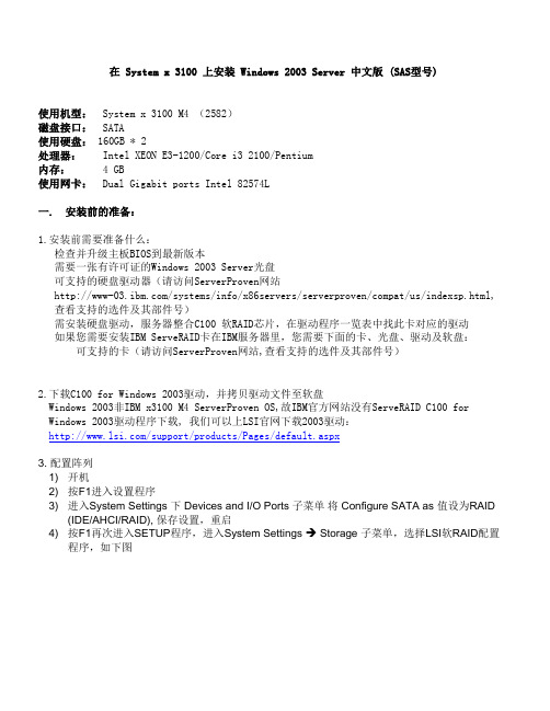
在 System x 3100 上安装 Windows 2003 Server 中文版 (SAS型号)使用机型:System x 3100 M4 (2582)磁盘接口:SATA使用硬盘: 160GB * 2处理器:Intel XEON E3-1200/Core i3 2100/Pentium内存: 4 GB使用网卡:Dual Gigabit ports Intel 82574L一. 安装前的准备:1.安装前需要准备什么:检查并升级主板BIOS到最新版本需要一张有许可证的Windows 2003 Server光盘可支持的硬盘驱动器(请访问ServerProven网站/systems/info/x86servers/serverproven/compat/us/indexsp.html, 查看支持的选件及其部件号)需安装硬盘驱动,服务器整合C100 软RAID芯片,在驱动程序一览表中找此卡对应的驱动如果您需要安装IBM ServeRAID卡在IBM服务器里,您需要下面的卡、光盘、驱动及软盘:可支持的卡(请访问ServerProven网站,查看支持的选件及其部件号)2.下载C100 for Windows 2003驱动,并拷贝驱动文件至软盘Windows 2003非IBM x3100 M4 ServerProven OS,故IBM官方网站没有ServeRAID C100 for Windows 2003驱动程序下载, 我们可以上LSI官网下载2003驱动:/support/products/Pages/default.aspx3. 配置阵列1) 开机2) 按F1进入设置程序3) 进入System Settings 下 Devices and I/O Ports 子菜单将 Configure SATA as 值设为RAID(IDE/AHCI/RAID), 保存设置,重启4) 按F1再次进入SETUP程序,进入System Settings Storage 子菜单,选择LSI软RAID配置程序,如下图5) 第一项为控制器配置,第二项是阵列管理,第三项是硬盘管理,这里我们选择第二项6) 选择Create Configuation7) 选择RAID级别,8) 选择硬盘9) 保存阵列配置10) 查看刚刚配置的阵列信息二. 操作系统安装1.启动服务器,插入“Windows Server 2003 (32 bit) 安装光盘”到CDROM驱动器,用光盘引导系统。
J2534

SAE Technical Standards Board Rules provide that: “This report is published by SAE to advance the state of technical and engineering sciences. The use of this report is entirely voluntary, and its applicability and suitability for any particular use, including any patent infringement arising therefrom, is the sole responsibility of the user.”SAE reviews each technical report at least every five years at which time it may be reaffirmed, revised, or cancelled. SAE invites your written comments and suggestions.TO PLACE A DOCUMENT ORDER: +1 (724) 776-4970 FAX: +1 (724) 776-0790SAE WEB ADDRESS Copyright 2002 Society of Automotive Engineers, Inc.TABLE OF CONTENTS1.Scope (4)2.References (4)2.1Applicable Publications (4)2.1.1SAE Publications (4)2.1.2ISO Documents (4)3.Definitions (4)4.Acronyms (5)5.Pass-Thru Concept (5)6.Pass-Thru System requirements (6)6.1PC requirements (6)6.2Software Requirements and Assumptions (6)6.3Connection to PC (6)6.4Connection to Vehicle (6)6.5Communication Protocols (6)6.5.1ISO 9141 (7)6.5.2ISO 14230-4 (KWP2000) (7)6.5.3SAE J1850 41.6 kbps PWM (pulse width modulation) (7)6.5.4SAE J1850 10.4 kbps VPW (variable pulse width) (7)6.5.5CAN (7)6.5.6ISO 15765-4 (CAN) (7)6.5.7SAE J2610 DaimlerChrysler SCI (7)6.6Programmable power supply (8)6.7Data Buffering (8)7.Win32 Application Programming Interface (8)7.1API Functions – Overview (8)7.2API Functions - Detailed Information (8)7.2.1PassThruConnect (8)7.2.2PassThruDisconnect (10)7.2.3PassThruReadMsgs (11)7.2.4PassThruWriteMsgs (12)7.2.5PassThruStartPeriodicMsg (13)7.2.6PassThruStopPeriodicMsg (14)7.2.7PassThruStartMsgFilter (14)7.2.8PassThruStopMsgFIlter (16)7.2.9PassThruSetProgrammingVoltage (17)7.2.10PassThruReadVersion (18)7.2.11PassThruGetLastError (19)7.2.12PassThruIoctl (19)7.3IOCTL Section (21)7.3.1GET_CONFIG (21)7.3.2SET_CONFIG (22)7.3.3READ_VBATT (25)7.3.4READ_PROG_VOLTAGE (26)7.3.5FIVE_BAUD_INIT (26)7.3.6FAST_INIT (26)7.3.7CLEAR_TX_BUFFER (27)7.3.8CLEAR_RX_BUFFER (27)7.3.9CLEAR_PERIODIC_MSGS (27)7.3.10CLEAR_MSG_FILTERS (27)7.3.11CLEAR_FUNCT_MSG_LOOKUP_TABLE (28)7.3.12ADD_TO_FUNCT_MSG_LOOKUP_TABLE (28)7.3.13DELETE_FROM_FUNCT_MSG_LOOKUP_TABLE (29)8.Message Structure (29)8.1 C / C++ Definition (29)8.2Elements (29)8.3Message Data Formats (30)8.3.1CAN Data Format (30)8.3.2ISO 15765-4 Data Format (30)8.3.3SAE J1850PWM Data Format (31)8.3.4SAE J1850VPW Data Format (31)8.3.5 ISO 9141 Data Format (32)8.3.6ISO 14230-4 Data Format (32)8.3.7SCI Data Format (32)8.4Message Flag and Status Definitions (33)8.4.1RxStatus (33)8.4.2TxFlags (33)9.DLL Installation and Registration (34)9.1Naming of Files (34)9.2Win32 Registration (34)9.2.1User Application Interaction with the Registry (36)9.2.2Attaching to the DLL from an application (37)10.Return Value Error Codes (37)Appendix A General ISO 15765-2 Flow Control Example (39)A.1Normal Addressing Used (39)A.2General Request Message Flow Example (39)A.3General Response Message Flow Example (40)Appendix B Message Filter Usage Example (42)B.1Filter Usage (42)B.2Transmission of a Multi-Frame Request Message (42)B.3Reception of a Multi-Frame Response Message (42)B.4Filter Configuration (42)B.4.1Request Message Transmission (44)B.4.2Response Message Reception (45)B.5ISO 15765-2 Extended Addressing Notes (46)1.Scope—This SAE Recommended Practice provides the framework to allow reprogramming softwareapplications from all vehicle manufacturers the flexibility to work with multiple vehicle data link interface tools from multiple tool suppliers. This system enables each vehicle manufacturer to control the programming sequence for electronic control units (ECU’s) in their vehicles, but allows a single set of programming hardware and vehicle interface to be used to program modules for all vehicle manufacturers.This document does not limit the hardware possibilities for the connection between the PC used for the software application and the tool (e.g., RS-232, RS-485, USB, Ethernet…). Tool suppliers are free to choose the hardware interface appropriate for their tool. The goal of this document is to ensure that reprogramming software from any vehicle manufacturer is compatible with hardware supplied by any tool manufacturer.The U.S. Environmental Protection Agency (EPA) and the California Air Resources Board (ARB) have proposed requirements for reprogramming vehicles for all manufacturers by the aftermarket repair industry.This document is intended to meet those proposed requirements for 2004 model year vehicles. Additional requirements for the 2005 model year may require revision of this document, most notably the inclusion of SAE J1939 for some heavy-duty vehicles. This document will be reviewed for possible revision after those regulations are finalized and requirements are better understood. Possible revisions include SAE J1939 specific software and an alternate vehicle connector, but the basic hardware of an SAE J2534 interface device is expected to remain unchanged.2.References2.1Applicable Publications—The following publications form a part of this specification to the extent specifiedherein. Unless otherwise indicated, the latest version of SAE publications shall apply.2.1.1SAE P UBLICATIO NS—Available from SAE, 400 Commonwealth Drive, Warrendale, PA 15096-0001.SAE J1850—Class B Data Communications Network InterfaceSAE J1939—Truck and Bus Control and Communications Network (multiple parts apply)SAE J1962—Diagnostic ConnectorSAE J2610—DaimlerChrysler Information Report for Serial Data Communication Interface (SCI)2.1.2ISO D O CUMENTS—Available from ANSI, 25 west 43rd Street, New York, NY 10036-8002.ISO 7637-1:1990—Road vehicles—Electrical disturbance by conduction and coupling—Part 1: Passenger cars and light commercial vehicles with nominal 12 V supply voltageISO 9141:1989—Road vehicles—Diagnostic systems—Requirements for interchange of digital information ISO 9141-2:1994—Road vehicles—Diagnostic systems—CARB requirements for interchange of digital informationISO 11898:1993—Road vehicles—Interchange of digital information—Controller area network (CAN) for high speed communicationISO 14230-4:2000—Road vehicles—Diagnostic systems—Keyword protocol 2000—Part 4: Requirements for emission-related systemsISO/DIS15765-2—Road vehicles—Diagnostics on controller area networks (CAN)—Network layer servicesISO/DIS15765-4—Road vehicles—Diagnostics on controller area networks (CAN)—Requirements for emission-related systems3.Definitions3.1Registry—A mechanism within Win32 operating systems to handle hardware and software configurationinformation.4.AcronymsAPI Application Programming InterfaceASCII American Standard for Character Information InterchangeCAN Controller Area NetworkCRC Cyclic Redundancy CheckDLL Dynamic Link LibraryECU Electronic Control UnitIFR In-Frame ResponseIOCTL Input / Output ControlKWP Keyword ProtocolOEM Original Equipment ManufacturerPC Personal ComputerPWM Pulse Width ModulationSCI Serial Communications InterfaceSCP Standard Corporate ProtocolUSB Universal Serial BusVPW Variable Pulse Width5.Pass-Thru Concept—Programming application software supplied by the vehicle manufacturer will run on acommonly available generic PC. This application must have complete knowledge of the programming requirements for the control module to be programmed and will control the programming event. This includes the user interface, selection criteria for downloadable software and calibration files, the actual software and calibration data to be downloaded, the security mechanism to control access to the programming capability, and the actual programming steps and sequence required to program each individual control module in the vehicle.This document defines the following two interfaces for the SAE J2534 pass-thru device:a.Application program interface (API) between the programming application running on a PC and asoftware device driver for the pass-thru deviceb.Hardware interface between the pass-thru device and the vehicleAll programming applications shall utilize the common SAE J2534 API as the interface to the pass-thru device driver. The API contains a set of routines that may be used by the programming application to control the pass-thru device, and to control the communications between the pass-thru device and the vehicle. The pass-thru device will not interpret the message content, allowing any message strategy and message structure to be used that is understood by both the programming application and the ECU being programmed. Also, because the message will not be interpreted, the contents of the message cannot be used to control the operation of the interface. For example, if a message is sent to the ECU to go to high speed, a specific instruction must also be sent to the interface to go to high speed.The manufacturer of an SAE J2534 pass-thru device must supply both the device driver software and the pass-thru device hardware that communicates directly with the vehicle. The interface between the PC and the pass-thru device can be any technology chosen by the tool manufacturer, including RS-232, RS-485, USB, Ethernet, or any other current or future technology, including wireless technologies.The OEM programming application does not need to know the hardware connected to the PC, which gives the tool manufacturers the flexibility to use any commonly available interface to the PC. The pass-thru device does not need any knowledge of the vehicle or control module being programmed. This will allow all programming applications to work with all pass-thru devices to enable programming of all control modules for all vehicle manufacturers.Figure 1 shows the relationship between the various components required for pass-thru programming and responsibilities for each component:FIGURE 1—SAE J2534 OVERVIEW6.Pass-Thru System Requirements6.1PC Requirements—Generic PC running a Win32 Operating System (e.g., Windows 95/Windows 98/WindowsNT/Windows Millennium Edition, Windows 2000, Windows XP, …). The PC should be capable of connection to the Internet.6.2Software Requirements and Assumptions—Reprogramming applications can assume that the PC will beconnected to the Internet, although not all applications will require this. The OEM application is limited to a single thread for communication with the tool manufacturer DLL/API. Multiple protocols may be connected and communicated on sequentially (serialized) from the single application thread. This will prevent the unnecessary complexity of determining what message responses belong to which application thread.6.3Connection to PC—The interface between the PC and the pass-thru device shall be determined by themanufacturer of the pass-thru device. This can be RS-232, USB, Ethernet, IEEE1394, Bluetooth or any other connection that allows the pass-thru device to meet all other requirements of this document, including timing requirements. The tool manufacturer is also required to include the device driver that supports this connection so that the actual interface used is transparent to both the PC programming application and the vehicle.6.4Connection to Vehicle—The interface between the pass-thru device and the vehicle shall be an SAE J1962connector for serial data communications. The maximum cable length between the pass-thru device and the vehicle is five (5) meters. Vehicle manufacturers will need to supply information about necessary connections to any connector other than the SAE J1962 connector.6.5Communication Protocols—A fully compliant pass-thru interface shall support all communication protocolsas specified in this section. Additionally, the pass-thru device must support simultaneous communication of an ISO 9141 OR ISO 14230-4 protocol AND an SAE J1850 protocol AND a CAN or SCI based protocol during a single programming event. Note that only one type of SAE J1850 is required per programming event, as the two types of SAE J1850 are mutually exclusive on any given vehicle. As well, CAN and SCI are mutually exclusive on some vehicles as the same pins are used.The following communication protocols shall be supported:6.5.1ISO 9141—The following specifications clarify and, if in conflict with ISO 9141, override any relatedspecifications in ISO 9141:a.The maximum sink current to be supported by the interface is 100 mA.b.The range for all tests performed relative to ISO 7637-1 is –1.0 to +40.0 V.c.The minimum bus idle period before the interface shall transmit an address, shall be 300 ms.d.Support following baud rate with ±0.5% tolerance: 10400.e.Support following baud rates with ±2% tolerance: 9600, 9615, 10000, 10870, 11905, 12500, 13158,13889, 14706, and 15625.f.Support odd and even parity in addition to the default of no parity, with seven or eight data bits.Always one start bit and one stop bit.6.5.2ISO 14230-4 (KWP2000)—The ISO 14230-4 protocol is the same as the ISO 9141 protocol with thefollowing additions:a.The interface will handle the tester present message and 0x78 response code automatically (i.e.,without intervention from the PC).6.5.3SAE J1850 41.6 KBPS PWM (PULSE WIDTH MODULATIO N)—The following additional features of SAE J1850must be supported by the pass-thru device for 41.6 kbps PWM:a.Capable of high speed mode of 83.3 kbps.b.Recommend Ford approved SAE J1850PWM(SCP) physical layer6.5.4SAE J1850 10.4 KBPS VPW (VARIABLE PULSE WIDTH)—The following additional features of SAE J1850 mustbe supported by the pass-thru device for 10.4 kbps VPW:a.High speed mode of 41.6 kbpsb.4K block transfer6.5.5CAN—The following features of ISO 11898 must be supported by the pass-thru device:a.250 and 500 kbpsb.11 and 29 bit identifiersc.Support for 80% ± 2% and 68.5% ± 2% bit sample pointd.Pass-thru message interface (i.e., raw CAN frames with no flow control in the pass-thru device)6.5.6ISO 15765-4 (CAN)—The following features of ISO 15765-4 must be supported by the pass-thru device:a.250 and 500 kbpsb.11 and 29 bit identifiersc.Support for 80% ± 2% bit sample pointd.To maintain acceptable programming times, the transport layer flow control function, as defined in ISO15765-2, must be incorporated in the pass-thru device (see Appendix A). If the application does notuse the ISO 15765-2 transport layer flow control functionality, the CAN protocol will allow for anycustom transport layer.6.5.7SAE J2610 D AIMLER C HRYSLER SCI—Reference the SAE J2610 Information Report for a description of theSCI protocol.6.6Programmable Power Supply—The interface shall be capable of supplying between 5 and 20 volts to one ofthe following pins (6, 9, 11, 12, 13 or 14) on the SAE J1962 diagnostic connector, or to an auxiliary pin which would need to be connected to the vehicle via a cable that is unique to the vehicle. As well, short to ground capability on pin 15 is required. The following requirements shall be met by the power supply:a.Minimum 5 Vb.Maximum 20 Vc.Accuracy ±0.1 Vd.Maximum source current 200 mAe.Maximum sink current 300mA (only for SHORT_TO_GROUND option).f.Maximum 1 ms settling time (required for SCI protocol, reference SAE J2610 Information Report)g.Pin assignment software selectable6.7Data Buffering—The interface shall be capable of buffering a 4K byte transmit message as well as a 4K bytereceive message.7.Win32 Application Programming Interface7.1API Functions – Overview—To conform to this document a vendor supplied API implementation (DLL) mustsupport the functions included in Figure 2.FIGURE 2—SAE J2534 API FUNCTIONS7.2API Functions - Detailed Information7.2.1P ASS T HRU C ONNECT—This function is used to establish a logical connection with a protocol channel. Afterthis function is called, the value pointed to by pChannelID is used as the logical identifier for the connection.The DLL can use this function to initialize data structures and device drivers. If the function operates successfully, a value of STATUS_NOERROR is returned and a valid channel ID will be placed in <pChannelID>. All future interactions with the protocol channel will be done using the pChannelID. Note that all filters for the given protocol will be cleared with this function.7.2.1.1 C / C++ Prototypeextern “C” long WINAPI PassThruConnect(unsigned long ProtocolID,unsigned long Flags,unsigned long *pChannelID)7.2.1.2ParametersProtocolID Protocol ID.Flags Connection flags, normally set to zero.pChannelID Pointer to location for the channel ID that is assigned by the DLL.7.2.1.3Flag Values—See Figure 3.FIGURE 3—FLAG VALUES7.2.1.4ProtocolID Values—See Figure 4.FIGURE 4—PROTOCOL ID VALUES7.2.1.5Return Values—See Figure 5.FIGURE 5—RETURN VALUES7.2.2P ASS T HRU D ISCONNECT—This function is used to terminate a logical connection with a protocol channel. TheDLL can use this function to de-allocate data structures and deactivate any device drivers. If the function operates successfully, a value of STATUS_NOERROR is returned. After this call the Channel ID will no longer be valid.7.2.2.1 C / C++ Prototypeextern “C” long WINAPI PassThruDisconnect(unsigned long ChannelID)7.2.2.2ParametersChannelID The channel ID assigned by the PassThruConnect function.7.2.2.3Return Values—See Figure 6.FIGURE 6—RETURN VALUES7.2.3P ASS T HRU R EAD M SGS—This function reads messages from the receive buffer in the order they werereceived. If the function operates successfully, a value of STATUS_NOERROR is returned. Note that the ISO 15765-2 FirstFrame and TxDone indications will be returned as messages when calling this function.Also note that all messages and indications shall be read in the order that they occurred on the bus.7.2.3.1 C / C++ Prototypeextern “C” long WINAPI PassThruReadMsgs(unsigned long ChannelID,PASSTHRU_MSG *pMsg,unsigned long *pNumMsgs,unsigned long Timeout)7.2.3.2ParametersChannelID The channel ID assigned by the PassThruConnect function.pMsg Pointer to message structure(s).pNumMsgs Pointer to location where number of messages to read is specified. On return from the function this location will contain the actual number of messages read.Timeout Read timeout (in milliseconds). If a value of 0 is specified the function returns immediately.Otherwise, the API will not return until the Timeout has expired, an error has occurred, or thedesired number of messages have been read. If the number of messages requested havebeen read, the function shall not return ERR_TIMEOUT, even if the timeout value is zero. 7.2.3.3Return Values—See Figure 7.FIGURE 7—RETURN VALUES7.2.4P ASS T HRU W RITE M S GS—This function is used to send messages. The messages are placed in the bufferand sent in the order they were received. If the function operates successfully, a value of STATUS_NOERROR is returned. To perform blocking writes (i.e., the function does not return until message is successfully sent on the vehicle network or a timeout occurs), use the blocking flag in the TxFlags element of the message structure (Reference 8.4.2).7.2.4.1 C / C++ Prototypeextern “C” long WINAPI PassThruWriteMsgs(unsigned long ChannelID,PASSTHRU_MSG *pMsg,unsigned long *pNumMsgs,unsigned long Timeout)7.2.4.2ParametersChannelID The channel ID assigned by the PassThruConnect function.pMsg Pointer to message structure(s).pNumMsgs Pointer to the location where number of messages to write is specified. On return will contain the actual number of messages that were transmitted or placed in the transmitqueue.Timeout Write timeout (in milliseconds). If a value of 0 is specified the function returns immediately.Otherwise, the API will not return until the Timeout has expired, an error has occurred, or thedesired number of messages have been written. If the number of messages requested havebeen written, the function shall not return ERR_TIMEOUT, even if the timeout value is zero.7.2.4.3Return Values—See Figure 8.FIGURE 8—RETURN VALUES7.2.5P ASS T HRU S TART P ERIODIC M SG—This function starts sending a message at the specified interval. If thefunction operates successfully, a value of STATUS_NOERROR is returned. The maximum number of periodic messages is ten.7.2.5.1 C / C++ Prototypeextern “C” long WINAPI PassThruStartPeriodicMsg(unsigned long ChannelID,PASSTHRU_MSG *pMsg,unsigned long *pMsgID,unsigned long TimeInterval)7.2.5.2ParametersChannelID The channel ID assigned by the PassThruConnect function.pMsg Pointer to message structure.pMsgID Pointer to location for the message ID that is assigned by the DLL.TimeInterval Time interval between the start of successive transmissions of this message, in milliseconds. The valid range is 5-65535 milliseconds.7.2.5.3Return Values—See Figure 9.FIGURE 9—RETURN VALUES7.2.6P ASS T HRU S TOP P ERIODIC M SG—This function stops the process of sending a periodic message. If thefunction operates successfully, a value of STATUS_NOERROR is returned. After this call the MsgID will be invalid.7.2.6.1 C / C++ Prototypeextern “C” long WINAPI PassThruStopPeriodicMsg(unsigned long ChannelID,unsigned long MsgID)7.2.6.2ParametersChannelID The channel ID assigned by the PassThruConnect function.MsgID Message ID that is assigned by the PassThruStartPeriodicMsg function.7.2.6.3Return Values—See Figure 10.FIGURE 10—RETURN VALUES7.2.7P ASS T HRU S TART M SG F ILTER—This function starts filtering incoming messages. If the function operatessuccessfully, a value of STATUS_NOERROR is returned. The maximum number of message filters is ten.See Appendices A and B for a description of the use of these message filters for transmission and reception of multi-frame messages.7.2.7.1 C / C++ Prototypeextern “C” long WINAPI PassThruStartMsgFilter(unsigned long ChannelID,unsigned long FilterType,PASSTHRU_MSG *pMaskMsg,PASSTHRU_MSG *pPatternMsg,PASSTHRU_MSG *pFlowControlMsg,unsigned long *pMsgID)7.2.7.2ParametersChannelID The channel ID assigned by the PassThruConnect function.FilterType Designates:PASS_FILTER – allows matching messages into the receive queue.BLOCK_FILTER - keeps matching messages out of the receive queue.FLOW_CONTROL_FILTER – defines a filter and outgoing flow control messageto support the ISO 15765-2 flow control mechanism.pMaskMsg Designates a pointer to the mask message that will be applied to each incoming message (i.e., the mask message that will be ANDed to each incoming message) tomask any unimportant bits.The usage of the pMaskMsg allows for configuring a filter that passes thru multiple CANidentifiers. In case the filter allows for the reception of multiple CAN identifiers thenthose messages are only allowed to be SingleFrame messages, because only a singleFlowControl CAN identifier can be specified.pPatternMsg Designates a pointer to the pattern message that will be compared to the incoming message after the mask message has been applied. If the result matches this patternmessage and the FilterType is PASS_FILTER, then the incoming message will added tothe receive queue (otherwise it will be discarded). If the result matches this patternmessage and the FilterType is BLOCK_FILTER, then the incoming message will bediscarded (otherwise it will be added to the receive queue). Message bytes in thereceived message that are beyond the DataSize of the pattern message will be treatedas “don’t care”.pFlowControlMsg Designates a pointer to an ISO 15765-2 flow control message. This message will be sent out when the received message ANDed with the message pointed to by pMaskMsgmatches the message pointed to by pPatternMsg and the interface is receiving asegmented message. This message shall only contain the message ID (and extendedaddress byte if the ISO15765_EXT_ADDR flag is set). The interface will provide thePCI bytes when this message is transmitted. To modify the BS and STmin values thatare used by the interface, reference the IOCTL section. This pointer only applies to theFLOW_CONTROL_FILTER type and must be set to NULL when the FilterType isPASS_FILTER or BLOCK_FILTER.pMsgID Pointer to location for the message ID that is assigned by the DLL.7.2.7.3Filter Type Values—See Figure 11.FIGURE 11—FILTER TYPE VALUES7.2.7.4Return Values—See Figure 12.FIGURE 12—RETURN VALUES7.2.8P ASS T HRU S TOP M SG FI LTER—This function stops the process of filtering messages. If the function operatessuccessfully, a value of STATUS_NOERROR is returned. After this call the MsgID will be invalid.7.2.8.1 C / C++ Prototypeextern “C” long WINAPI PassThruStopMsgFilter(unsigned long ChannelID,unsigned long MsgID)7.2.8.2PrametersChannelID The channel ID assigned by the PassThruConnect function.MsgID Message ID that is assigned by the PassThruStartMsgFilter function.7.2.8.3Return Values—See Figure 13.FIGURE 13—RETURN VALUES7.2.9P ASS T HRU S ET P ROGRAMMING V OLTAG E—This function sets a programming voltage on a specific pin. If thefunction operates successfully, a value of STATUS_NOERROR is returned. It is up to the application programmer to insure that voltages are not applied to any pins incorrectly. This function cannot protect from incorrect usage (e.g., applying a voltage to pin 6 when it is being used for the CAN protocol). Note that for SCI protocol, the application would set the PinNumber, set the Voltage to VOLTAGE_OFF, and set SCI_TX_VOLTAGE in TxFlags of the message to pulse the programming voltage to 20 V DC.7.2.9.1 C / C++ Prototypeextern “C” long WINAPI PassThruSetProgrammingVoltage(unsigned long PinNumber,unsigned long Voltage)7.2.9.2ParametersPinNumber The pin on which the programming voltage will be set. Valid options are:0 – Auxiliary output pin (for non-SAE J1962 connectors)6 – Pin 6 on the SAE J1962 connector.9 – Pin 9 on the SAE J1962 connector.11 – Pin 11 on the SAE J1962 connector.12 – Pin 12 on the SAE J1962 connector.13 – Pin 13 on the SAE J1962 connector.14 – Pin 14 on the SAE J1962 connector.15 – Pin 15 on the SAE J1962 connector (short to ground only).Voltage The voltage (in millivolts) to be set. Valid values are:5000mV-20000mV (limited to 200mA with a resolution of ±100 millivolts for pins 0, 6, 9, 11,12, 13, and 14).VOLTAGE_OFF – To turn output off (disconnect).SHORT_TO_GROUND – Short pin to ground (pin 15 only).7.2.9.3Voltage Values—See Figure 14.FIGURE 14—VOLTAGE VALUES7.2.9.4Return Values—See Figure 15.FIGURE 15—RETURN VALUES7.2.10P ASS T HRU R EAD V ERSION—This function returns the version strings associated with the DLL. If the functionoperates successfully, a value of STATUS_NOERROR is returned. A buffer of at least eighty (80) characters must be allocated for each pointer by the application.7.2.10.1 C / C++ Prototypeextern “C” long WINAPI PassThruReadVersion(char*pFirmwareVersion,char*pDllVersion,char*pApiVersion)7.2.10.2ParameterspFirmwareVersion Pointer to Firmware version string in XX.YY format (e.g., 01.01). This string isdetermined by the interface vendor that supplies the device.pDllVersion Pointer to DLL version string in XX.YY format (e.g., 01.01). This string is determinedby the interface vendor that supplies the DLL.pApiVersion Pointer to API version string in XX.YY format. This string corresponds to the date ofthe balloted document.October 2001 Ballot = “01.01”December 2001 Ballot = “01.02”February 2002 Final = “02.02”7.2.10.3Return Values—See Figure 16.FIGURE 16—RETURN VALUES。
SAE J1704-2003 硼酸醋型制动液

SAE Technical Standards Board Rules provide that: “This report is published by SAE to advance the state of technical and engineering sciences. The use of this report is entirely voluntary, and its applicability and suitability for any particular use, including any patent infringement arising therefrom, is the sole responsibility of the user.”SAE reviews each technical report at least every five years at which time it may be reaffirmed, revised, or cancelled. SAE invites your written comments and suggestions.Copyright © 2003 SAE InternationalAll rights reserved. No part of this publication may be reproduced, stored in a retrieval system or transmitted, in any form or by any means, electronic, mechanical, photocopying,recording, or otherwise, without the prior written permission of SAE.TO PLACE A DOCUMENT ORDER:Tel: 877-606-7323 (inside USA and Canada)Tel: 724-776-4970 (outside USA)Fax: 724-776-0790Email: custsvc@SAE WEB ADDRESS: J1Borate Ester Based Brake Fluids1.Scope—This SAE Recommended Practice was prepared to provide engineers, designers, and manufacturersof motor vehicles with a set of minimum performance standards which covers the next level of performanceproperties above those of the present SAE J1703 brake fluid standard. These fluids are not intended for useunder arctic conditions or in braking systems requiring the use of mineral oil based hydraulic fluid.These fluids are designed for use in braking systems fitted with rubber cups and seals made from naturalrubber (NR), styrene-butadiene rubber (SBR), or a terpolymer of ethylene, propylene, and a diene (EPDM).These fluids are not designed to operate in a pumped or a clutch braking system, especially those hydraulicsystems requiring a mineral oil based fluid.2.References 2.1Applicable Publications—The following publications form a part of this specification to the extent specifiedherein. The latest issue of SAE publications shall apply.2.1.1SAE P UBLICATIONS —Available from SAE, 400 Commonwealth Drive, Warrendale, PA 15096-0001.SAE J527—Brazed Double Wall Low Carbon Steel TubingSAE J1703—Motor Vehicle Brake Fluid 2.1.2ASTM P UBLICATIONS —Available from ASTM, 100 Barr Harbor Drive, West Conshohocken, PA 19428-2959.ASTM D 91—Test Method for Precipitation Number of Lubricating OilsASTM D 395—T est Methods for Rubber Property—Compression SetASTM D 412—T est Methods for Rubber Properties in TensionASTM D 445—T est Method for Kinematic Viscosity of T ransparent and Opaque Liquids (and theCalculation of Dynamic Viscosity)ASTM D 664—T est Method for Neutralization Number of Potentiometric TitrationASTM D 746—T est Method for Brittleness Temperature of Plastics and Elastomers by ImpactASTM D 865—T est Method for Rubber—Deterioration by heating in Air (Test T ube Enclosure)ASTM D 1120—Method of Test for Boiling Point of Engine CoolantsASTM D 1209—Test Method for Color of Clear Liquids (Platinum-Cobalt Pigments)ASTM D 1364—Test Method for Water in Volatile Solvents (Fischer Reagent Titration Method)ASTM D 1415—Method of Test for International H ardness of Vulcanized Natural Rubber and SyntheticRubbersASTM D1613—T est Method for Acidity in Volatile Solvents and Chemical Intermediates Used in Paint, Varnish, Lacquer, and Related ProductsASTM D 2240—Method of T est for Indentation Hardness of Rubber and Plastics by Means of a Durometer ASTM D3182—Recommended Practice for Rubber-Materials, Equipment, and Procedures for Mixing Standard Compounds and Preparing Standard Vulcanized SheetsASTM D3185—Methods for Rubber-Evaluation of SBR (Styrene-Butadiene Rubber) including Mixtures with OilASTM E 1—Specification for ASTM ThermometersASTM E 145—Specification for Gravity-Convection and Forced-Ventilation Ovens2.2Related Publications—The following publications are provided for information purposes only and are not arequired part of this document.2.2.1ASTM P UBLICATIONS—Available from ASTM, 100 Barr Harbor Drive, West Conshohocken, PA 19428-2959.ASTM D 344—Method of Test for Relative Dry Hiding Power of PaintsASTM E 260—Standard Recommended Practice for General Gas Chromatography ProcedureASTM E 298—Evaluation of Benzoyl Peroxides3.Materials—The quality of the materials used shall be such that the resulting product will conform to therequirements of these specifications and ensure uniformity of performance.4.Requirements4.1Equilibrium Reflux Boiling Point (ERBP)—Brake fluid when tested by the procedure specified in5.1 shallhave an equilibrium reflux boiling point not less than 230 °C (446 °F).4.2Wet Equilibrium Reflux Boiling Point—Brake fluid when tested by the procedure specified in5.2 shall have awet equilibrium reflux boiling point not less than 155 °C (311 °F).4.3Viscosity—Brake fluid when tested by the procedure specified in5.3 shall have the following kinematicviscosities:4.3.1A T –40 °C (–40 °F)—Not more than 1800 mm2/s (1800 cSt)4.3.2A T 100 °C (212 °F)—Not less than 1.5 mm2/s (1.5 cSt)4.4pH Value—Brake fluid when tested by the procedure specified in5.4 shall have a pH value not less than 7.0and not more than 11.5.4.5Fluid Stability4.5.1H IGH-T EMPERATURE S TABILITY—When tested by the procedure specified in 5.5.1, the equilibrium refluxboiling point of the brake fluid shall not change by more than 5 °C (9 °F) increase or decrease.4.5.2C HEMICAL S TABILITY—When tested by the procedure specified in 5.5.2 the test fluid mixture shall show nochemical reversion as evidenced by a change in recorded temperature of more than 5 °C (9 °F) increase or decrease.-2-标准分享网 免费下载-3-4.6Corrosion—See T able 1.4.6.1D RY F LUID (AS RECEIVED )—Brake fluid, when tested by the procedure specified in5.6.1, shall not causecorrosion exceeding the limits shown in Table 1. The metal strip outside of the area where the strips are in contact shall neither be pitted nor roughened to an extent discernible to the naked eye, but staining or discoloration is permitted. The fluid at the end of the test shall show no jelling at 23 °C ± 5 °C (73.4 °F ±9°F). No crystalline-type deposit shall form and adhere to either the glass walls or the surface of the metal strips. The fluid shall not contain more than 0.10% sediment by volume.The rubber specimens at the end of the test shall show no disintegration, as evidenced by blisters or sloughing indicated by carbon black separation on the surface of the rubber cup.4.6.2B RAKE F LUID WITH WATER —The brake fluid containing water, when tested by the procedure specified in5.6.2,shall not cause corrosion exceeding the limits shown in Table 1. The metal strip outside of the area where the strips are in contact shall neither be pitted nor roughened to an extent discernible to the naked eye, but staining or discoloration is permitted. The fluid/water mixture at the end of the test shall show no jelling at 23°C ± 5 °C (73.4 °F ± 9 °F). No crystalline-type deposit shall form and adhere to either the glass walls or the surface of the metal strips. The fluid/water mixture shall not contain more than 0.10% sediment by volume. The fluid/water mixture shall have a pH of not less than 7.0 and not more than 11.5.The rubber test specimens at the end of the test shall show no disintegration, as evidenced by blisters or sloughing indicated by carbon black separation on the surface of the rubber cup. The hardness of the SBR cup shall not decrease by more than 15 IRHD and the hardness of the EPDM rubber specimen shall not decrease by more than 10 IRHD. The SBR rubber cup shall not decrease in volume and shall not increase in volume by more than 16%. The EPDM rubber specimen shall not decrease in volume and shall not increase in volume by more than 10%.4.7Fluidity and Appearance at Low Temperatures 4.7.1A T –40 °C (–40 °F)—When brake fluid is tested by the procedure specified in 5.7.1, the fluid shall show nostratification, sedimentation, or crystallization. Upon inversion of the sample bottle, the air bubble shall travel to the top of the fluid in not more than 10 s. Cloudiness is permissible, but on warming to room temperature 23 °C ± 5 °C (73.4 °F ± 9 °F), this fluid shall regain its original unformity, appearance, and clarity.4.7.2A T –50 °C (–58 °F)—When brake fluid is tested by the procedure specified in 5.7.2, the fluid shall show no stratification, sedimentation, or crystallization. Upon inversion of the sample bottle, the air bubble shall travel to the top of the fluid in not more than 35 s. Cloudiness is permissible, but on warming to room temperature 23 °C ± 5 °C (73.4 °F ± 9 °F), the fluid shall regain its original unformity, appearance , and clarity.TABLE 1—CORROSION TEST STRIPS AND WEIGHT CHANGESTest Strips (1)1.Obtainable from the Society of Automotive Engineers, 400 Common-wealth Drive, Warrendale, P A 15096-0001.RM Number Maximum PermissibleWeight Change(mg/cm 2 of surface area)Tinned Iron6A 0.2Steel70.2Aluminum80.1Cast Iron90.2Brass100.4Copper 110.44.8Water Tolerance4.8.1A T –40 °C (–40 °F)—When the humidified brake fluid is tested by the procedure specified in5.8.1, the blackcontrast lines on a hiding power chart shall be clearly discernible when viewed through the fluid in the centrifuge tube. The fluid shall show no stratification or sedimentation. Upon inversion of the centrifuge tube, the air bubble shall travel to the top of the fluid in not more than 10 s.4.8.2A T 60 °C (140 °F)—When brake fluid is tested by the procedure specified in5.8.2, the fluid shall show nostratification, and sedimentation shall not exceed 0.05% by volume after centrifuging when fluid is tested for qualification, or shall not exceed 0.15% by volume for a commercial packaged fluid.4.9Compatibility4.9.1A T –40 °C (–40 °F)—When brake fluid is tested by the procedure specified in5.9.1, the black contrast lineson a hiding power chart shall be clearly discernible when viewed through the fluid in the centrifuge tube. The fluid shall show no stratification or sedimentation.4.9.2A T 60 °C (140 °F)—When brake fluid is tested by the procedure specified in5.9.2, the fluid shall show nostratification, and sedimentation shall not exceed 0.05% by volume after centrifuging.4.10Resistance to Oxidation—When the humidified brake fluid is tested by the procedure specified in5.10, itshall not cause the metal strips outside the areas in contact with the tinfoil to be pitted or roughened to an extent discernible to the naked eye, but staining or discoloration is permitted. No more than a trace of gum shall be deposited on the test strips outside of the areas in contact with the tinfoil. The aluminum strips shall not change in mass by more than 0.05 mg/cm2 and the cast iron strips shall not change in mass by more than0.3 mg/cm2.4.11Effect on Rubber4.11.1Rubber brake cups (RM-3a) subjected to brake fluid as specified in5.11.1 shall show no increase inhardness, shall not decrease in hardness by more than 10 IRH D, and shall show no disintegration as evidenced by blisters or sloughing indicated by carbon black separation on the surface of the rubber cup.Volume increase shall not be less than 1% or greater than 16%.4.11.2Rubber brake cups (RM-3a) subjected to brake fluid as specified in5.11.2 shall show no increase inhardness, shall not decrease in hardness by more than 15 IRH D and shall show no disintegration as evidenced by blisters or sloughing indicated by carbon black separation on the surface of the rubber cup.Volume increase shall not be less than 1% or greater than 16%.4.11.3Rubber slab stock (RM-69) subjected to brake fluid, as specified in5.11.3, shall show no increase inhardness, shall not decrease in hardness by more than 10 IRH D, and shall show no disintegration as evidenced by blisters or sloughing indicated by carbon black separation on the surface of the test specimens.The test specimens shall not decrease in volume and the increase in volume shall not exceed 10%.4.11.4Rubber slab stock (RM-69) subjected to brake fluid, as specified in5.11.4, shall show no increase inhardness, shall not decrease in hardness by more than 15 IRH D, and shall show no disintegration as evidenced by blisters or sloughing indicated by carbon black separation on the surface of the test specimens.The test specimens shall not decrease in volume and the increase in volume shall not exceed 10%.-4-标准分享网 免费下载5.Test Procedures5.1Equilibrium Reflux Boiling Point—Determine the equilibrium reflux boiling point of the fluid by ASTM D 1120with the following exceptions:5.1.1 A PPARATUS5.1.1.1 4.4 Thermometer—ASTM E 1, 76 mm immersion, calibrated. Use ASTM 3C or 3F thermometer. Forfluids boiling below 300 °C, ASTM 2C or 2F thermometer may be used.5.1.1.2 4.5 Heat Source—Use a suitable variac-controlled 100 mL heating mantle designed to fit the flask, capableof supplying the heat required to conform to the specified heating and reflux rates. (Supplier: GLAS COL Apparatus Co., Terre Haute, IN. Serial number: 135464. 230 W, 135 V [max.])5.1.1.3Boiling Point Stones RM-755.1.1.4Preparation of Apparatus—6.4 Thoroughly clean and dry all glassware before use. Attach the flask to thecondenser. Place the mantle under the flask and support it with a suitable ring clamp and laboratory-type stand, holding the whole assembly in place by a clamp.NOTE—Place the whole assembly in an area free from drafts or other types of sudden temperature changes.5.1.2P ROCEDURE—7.1 When everything is in readiness, turn on the condenser water and apply heat to the flask atsuch a rate that the fluid is refluxing in 10 min ± 2 min at a rate in excess of 1 drop/s. Immediately adjust heat input to obtain a specified equilibrium reflux rate of 1 to 2 drops/s over the next 5 min ± 2 min period.Maintain a timed and constant equilibrium reflux rate of 1 to 2 drops/s for an additional 2 min; record the average value of four temperature readings taken at 30 s intervals as the equilibrium reflux boiling point.5.1.2.1Report the boiling point to the nearest degree Celsius. Duplicate runs which agree within 3 °C areacceptable for averaging (95% confidence level).5.2Wet Equilibrium Reflux Boiling Point—Humidify the fluid and determine the boiling point.5.2.1H UMIDIFICATION P ROCEDURE—Lubricate the ground-glass joint of a 250 mm ID bowl-form desiccator havingmatched tubulated glass cover and fitted with a No. 8 rubber stopper. Pour 450 mL ± 10 mL of distilled water into the dessicator and insert a perforated porcelain plate (Coors No. 60456 or equivalent). Immediately place one open RM-49 corrosion test jar containing 350 mL ± 5 mL of the test brake fluid into the dessicator.Place a second open RM-49 corrosion test jar containing 350 mL ± 5 mL of TEGME (triethylene glycol monomethyl ether, brake fluid grade - Appendix E) (RM-71) into the same desiccator. The water content of the TEGME control fluid at the start of exposure shall have been adjusted to 0.50% ± 0.05% by weight (Karl Fischer analysis or equivalent). Replace desiccator cover and insert at once into an ASTM E 145, Type II A, forced ventilation oven set at 50 °C ± 1 °C (122 °F ± 1.8 °F).Periodically, during oven humidification, remove the rubber stopper from the desiccator and, using a long needle hypodermic syringe, quickly sample the control fluid and determine its water content. When the water content of the control fluid has reached 3.70% ± 0.05% by weight, remove the dessicator from the oven and seal the test jar promptly using a screw-cap lid (RM-63). Allow the sealed jar to cool for 60 to 90 min at 23 °C ± 5 °C (73.4 °F ± 9 °F).5.2.2W ET E QUILIBRIUM R EFLUX B OILING P OINT—Humidify the fluid as described in 5.2.1 and determine the boilingpoint as described in 5.1.-5-5.3Viscosity—Determine the kinematic viscosity of the fluid by ASTM D 445.5.3.1Report the viscosity to the nearest mm2/s (centistoke). Duplicate runs which agree within 1.2% relative areacceptable for averaging (95% confidence level).5.4pH Value—Mix the fluid with an equal volume of an 50% ethanol/50% distilled water mixture neutralized to apH of 7. Determine the pH of the resulting solution electrometrically at 23 °C ± 5 °C (73.4 °F ± 9 °F) using a pH meter equipped with a calibrated full range (0 to 14) glass electrode and a calomel reference electrode, as specified in ASTM D 664.5.5Fluid Stability5.5.1H IGH T EMPERATURE S TABILITY—Heat a new sample of the original test brake fluid to a temperature of 185 °C± 2 °C (365 °F ± 3.6 °F) by the procedure specified in 5.1 and maintain at that temperature for 2 h. Then determine the boiling point of this brake fluid as specified in 5.1. The difference between this observed boiling point and that previously determined in 5.1 shall be considered as the change in boiling point of the brake fluid.5.5.2C HEMICAL S TABILITY—Mix 30 mL of brake fluid with 30 mL of SAE Compatibility Fluid described in AppendixB (RM-66-05). Determine the equilibrium reflux boiling point of this fluid mixture by use of the test apparatusspecified in 5.1, applying heat to the flask at such a rate that the fluid is refluxing in 10 min ± 2 min at a rate in excess of 1 drop/s. The reflux rate shall not exceed 5 drops/s. Record the maximum fluid temperature observed during the first minute after the fluid begins refluxing at a rate in excess of 1 drop/s. Over the next15 min ± 1 min, adjust and maintain the rate of reflux to 1 to 2 drops/s. Maintain a timed and constantequilibrium reflux rate of 1 to 2 drops/s for an additional 2 min; record the average value of four temperature readings taken at 30 s intervals as the final equilibrium reflux boiling point. Chemical reversion is evidenced by the decrease in temperature between the maximum fluid temperature recorded and the final equilibrium reflux boiling point.5.6Corrosion5.6.1D RY F LUID (AS RECEIVED)—Prepare two sets of strips from each of the metals listed in Table 1, each striphaving a surface area of 25 cm2 ± 5 cm2 (approximately 8 cm long, 1.3 cm wide, and not more than 0.6 cm thick). Drill a hole between 4 and 5 mm in diameter and about 6 mm from one end of each strip. With the exception of the tinned iron strips, clean the strips by abrading them on all surface areas with 320A (RM-29) or P400 waterproof carborundum paper and isopropanol or ethanol until all surface scratches, cuts, and pits are removed from the strips, using a new piece of carborundum paper for each different type of metal. Wash the strips, including the tinned iron, with isopropanol or ethanol and dry the strips with a clean lint-free cloth and place strips in a desiccator containing desiccant maintained at 23 °C ± 5 °C (73.4 °F ± 9 °F) for at least1 h.Handle the strips with clean forceps after polishing to avoid fingerprint contamination.Weigh each strip to the nearest 0.1 mg and assemble each set of strips on an uncoated steel bolt (RM-61) in the order tinned iron, steel, aluminum, cast iron, brass, and copper, so that the strips are in electrolytic contact. Bend the strips, other than cast iron, so that there is a separation of at least 3 mm between adjacent strips for a distance of about 6 cm from the free end of the strips. (Immerse strip assemblies in isopropanol or ethanol to eliminate fingerprints and then handle only with clean forceps.)Use two SBR cups (RM-3a) and two 25.4 mm x 25.4 mm (1 in x 1 in) EPDM rubber slab stock (RM-69) test specimens as described in Appendix C and Appendix D, respectively.-6-标准分享网 免费下载Obtain two straight-sided round glass jars, having a capacity of approximately 475 mL and inner dimensions of approximately 100 mm in height and 75 mm in diameter (RM-49). T o the RM-49 corrosion test jar, apply four wrappings of 19 mm (3/4 in) Teflon tape around the jar threads allowing a 3 mm (1/8 in) height above the top of the jar. Place one SBR cup (RM-3a) with lip edge facing up, in each of the two glass jars. Use only tinned steel lids vented with a hole 0.8 mm ± 0.1 mm in diameter (RM-64).Insert a metal strip assembly inside each cup with the bolted end in contact with the concavity of the cup and the free end extending upward in the jar. Place one EPDM rubber slab stock (RM-69) test specimen flat on the bottom of the test jar.Add 400 mL of fluid to cover the metal strip assembly in each jar. Tighten the lid and place the jars in an oven maintained at 100 °C ± 2 °C (212 °F ± 3.6 °F) for 120 h ± 2 h. Allow the jars to cool at 23 °C ± 5 °C(73.4 °F ± 9 °F) for 60 to 90 min. Immediately following the cooling period, remove the metal strips from thejars by use of a forceps, removing loose adhering sediment by agitation of the metal strip assembly in the fluid in the jar. Examine test strips and test jars for adhering crystalline deposit, disassemble the metal strips, removing adhering fluid by flushing with water, and clean individual strips by wiping with a cloth wetted with isopropanol or ethanol. Examine the strips for evidence of corrosion and pitting. Place strips in a desiccator containing a desiccant maintained at 23°C ± 5 °C (73.4 °F ± 9 °F) for at least 1 h. Weigh each strip to the nearest 0.1 mg.Determine the difference in weight of each metal strip and divide the difference by the total surface area of the metal strip measured in square centimeters. Average the measured quantities of the duplicates. In the event of a marginal pass on inspection, or of a failure in only one of the duplicates, another set of duplicate test samples shall be run. Both repeat samples must meet all the requirements of 4.6.Immediately following the cooling period, remove the rubber cups from the jars by use of a forceps, removing loose adhering sediment by agitation of the cup in the fluid in the jar.Rinse the rubber specimens in isopropanol or ethanol and air dry cups. Examine the rubber specimens for evidence of sloughing, blisters, and other forms of disintegration.Examine the fluid in the jars for jelling. Agitate the fluid in the jars to suspend and uniformly disperse sediment and transfer a 100 mL portion of this fluid to an ASTM cone-shaped centrifuge tube and determine percent sediment as described in 5.2 of ASTM D 91.Measure the pH value of the corrosion test fluid by the procedure specified in 5.4.5.6.2C ORROSION T EST ON B RAKE F LUID WITH W ATER—Same test procedure as 5.6.1 except the test is performedon a brake fluid containing 5% by volume water.Prepare two sets of strips from each of the metals listed in Table 1 (see Appendix A), each strip having a surface area of 25 cm2 ± 5 cm2 (approximately 8 cm long, 1.3 cm wide, and not more than 0.6 cm thick). Drilla hole between 4 and 5 mm in diameter and about 6 mm from one end of each strip. With the exception ofthe tinned iron strips, clean the strips by abrading them on all surface areas with 320A or P400 waterproof carborundum paper (RM-29) and isopropanol or ethanol until all surface scratches, cuts, and pits are removed from the strips, using a new piece of carborundum paper for each different type of metal. Wash the strips, including the tinned iron, with isopropanol or ethanol and dry the strips with a clean lint-free cloth and place strips in a desiccator containing desiccant maintained at 23 °C ± 5 °C (73.4 °F ± 9 °F) for at least 1 h.Handle the strips with clean forceps after polishing to avoid fingerprint contamination.-7-Weigh each strip to the nearest 0.1 mg and assemble each set of strips on an uncoated steel bolt (RM-61) in the order tinned iron, steel, aluminum, cast iron, brass, and copper, so that the strips are in electrolytic contact. Bend the strips, other than cast iron, so that there is a separation of at least 3 mm between adjacent strips for a distance of about 6 cm from the free end of the strips. (Immerse strip assemblies in isopropanol or ethanol to eliminate fingerprints and then handle only with clean forceps.)Use two SBR cups (RM-3a) and two 25.4 mm x 25.4 mm (1 in x 1 in) EPDM rubber slab stock (RM-69) test specimens as described in Appendix C and Appendix D, respectively.Determine the weight of the cups and rubber slab stock in air (m1) to the nearest 1 mg then determine the apparent weight of the cup and slab stock immersed in distilled water at room temperature (m2). Quickly dip each specimen in alcohol and then blot dry with filter paper free of lint and foreign matter. Measure the hardness of each specimen by the procedure specified in ASTM D 1415 using the Standards Tester.NOTE—ASTM D 2240 may be used for quality control and routine tests when a type A durometer is equipped with a fixture for keeping the plane of the pressure foot on the durometer parallel to the plane of the cup face during measurement.Obtain two straight-sided round glass jars, having a capacity of approximately 475 mL and inner dimensions of approximately 100 mm in height and 75 mm in diameter (RM-49). T o the RM-49 corrosion test jar, apply four wrappings of 19 mm (3/4 in) Teflon tape around the jar threads allowing a 3 mm (1/8 in) height above the top of the jar. Place one SBR cup (RM-3a) with lip edge facing up, in each of the two glass jars. Use only tinned steel lids vented with a hole 0.8 mm ± 0.1 mm in diameter (RM-64).Insert a metal strip assembly inside each cup with the bolted end in contact with the concavity of the cup and the free end extending upward in the jar. Place one EPDM rubber slab stock (RM-69) test specimen flat on the bottom of the test jar.Mix 760 mL of fluid with 40 mL of distilled water.Add 400 mL of the mixture to cover the metal strip assembly in each jar. Tighten the lid and place the jars in an oven maintained at 100 °C ± 2 °C (212 °F ± 3.6 °F) for 120 h ± 2 h. Allow the jars to cool at 23 °C ± 5 °C (73.4 °F ± 9 °F) for 60 to 90 min. Immediately following the cooling period, remove the metal strips from the jars by use of a forceps, removing loose adhering sediment by agitation of the metal strip assembly in the fluid in the jar. Examine test strips and test jars for adhering crystalline deposit, disassemble the metal strips, removing adhering fluid by flushing with water, and clean individual strips by wiping with a cloth wetted with isopropanol or ethanol. Examine the strips for evidence of corrosion and pitting. Place strips in a desiccator containing a desiccant maintained at 23 °C ± 5 °C (73.4 °F ± 9 °F) for at least 1 h. Weigh each strip to the nearest 0.1 mg.Determine the difference in weight of each metal strip and divide the difference by the total surface area of the metal strip measured in square centimeters. Average the measured quantities of the duplicates. In the event of a marginal pass on inspection, or of a failure in only one of the duplicates, another set of duplicate test samples shall be run. Both repeat samples must meet all the requirements of 4.6.Immediately following the cooling period, remove the rubber cups from the jars by use of a forceps, removing loose adhering sediment by agitation of the cup in the fluid in the jar.Rinse the rubber specimens in isopropanol or ethanol and air dry cups. Examine the rubber specimens for evidence of sloughing, blisters, and other forms of disintegration.Within 15 min after removal from the fluid, weigh each specimen in air (m3), again to the nearest milligram, then reweigh immersed in room temperature distilled water (m4) to determine the volume change after hot fluid immersion.-8-标准分享网 免费下载。
SN74HC151DE4中文资料

PACKAGING INFORMATIONOrderable DeviceStatus (1)Package Type Package Drawing Pins Package Qty Eco Plan (2)Lead/Ball FinishMSL Peak Temp (3)84128012A ACTIVE LCCC FK 201TBD POST-PLATE N /A for Pkg Type 8412801EA ACTIVE CDIP J 161TBD A42SNPB N /A for Pkg Type SN54HC151J ACTIVE CDIP J 161TBD A42SNPB N /A for Pkg Type SN74HC151D ACTIVE SOIC D 1640Green (RoHS &no Sb/Br)CU NIPDAU Level-1-260C-UNLIM SN74HC151DE4ACTIVE SOIC D 1640Green (RoHS &no Sb/Br)CU NIPDAU Level-1-260C-UNLIM SN74HC151DG4ACTIVE SOIC D 1640Green (RoHS &no Sb/Br)CU NIPDAU Level-1-260C-UNLIM SN74HC151DR ACTIVE SOIC D 162500Green (RoHS &no Sb/Br)CU NIPDAU Level-1-260C-UNLIM SN74HC151DRE4ACTIVE SOIC D 162500Green (RoHS &no Sb/Br)CU NIPDAU Level-1-260C-UNLIM SN74HC151DRG4ACTIVE SOIC D 162500Green (RoHS &no Sb/Br)CU NIPDAU Level-1-260C-UNLIM SN74HC151DT ACTIVE SOIC D 16250Green (RoHS &no Sb/Br)CU NIPDAU Level-1-260C-UNLIM SN74HC151DTE4ACTIVE SOIC D 16250Green (RoHS &no Sb/Br)CU NIPDAU Level-1-260C-UNLIM SN74HC151N ACTIVE PDIP N 1625Pb-Free (RoHS)CU NIPDAU N /A for Pkg Type SN74HC151NE4ACTIVE PDIP N 1625Pb-Free (RoHS)CU NIPDAU N /A for Pkg Type SN74HC151NSR ACTIVE SO NS 162000Green (RoHS &no Sb/Br)CU NIPDAU Level-1-260C-UNLIM SN74HC151NSRE4ACTIVE SO NS 162000Green (RoHS &no Sb/Br)CU NIPDAU Level-1-260C-UNLIM SN74HC151PW ACTIVE TSSOP PW 1690Green (RoHS &no Sb/Br)CU NIPDAU Level-1-260C-UNLIM SN74HC151PWE4ACTIVE TSSOP PW 1690Green (RoHS &no Sb/Br)CU NIPDAU Level-1-260C-UNLIM SN74HC151PWR ACTIVE TSSOP PW 162000Green (RoHS &no Sb/Br)CU NIPDAU Level-1-260C-UNLIM SN74HC151PWRE4ACTIVE TSSOP PW 162000Green (RoHS &no Sb/Br)CU NIPDAU Level-1-260C-UNLIM SN74HC151PWT ACTIVE TSSOP PW 16250Green (RoHS &no Sb/Br)CU NIPDAU Level-1-260C-UNLIM SN74HC151PWTE4ACTIVE TSSOP PW 16250Green (RoHS &no Sb/Br)CU NIPDAULevel-1-260C-UNLIMSNJ54HC151FK ACTIVE LCCC FK 201TBD POST-PLATE N /A for Pkg Type SNJ54HC151JACTIVECDIPJ161TBDA42SNPBN /A for Pkg Type(1)The marketing status values are defined as follows:ACTIVE:Product device recommended for new designs.LIFEBUY:TI has announced that the device will be discontinued,and a lifetime-buy period is in effect.NRND:Not recommended for new designs.Device is in production to support existing customers,but TI does not recommend using this part in a new design.PREVIEW:Device has been announced but is not in production.Samples may or may not be available.OBSOLETE:TI has discontinued the production of the device.6-Dec-2006(2)Eco Plan -The planned eco-friendly classification:Pb-Free (RoHS),Pb-Free (RoHS Exempt),or Green (RoHS &no Sb/Br)-please check /productcontent for the latest availability information and additional product content details.TBD:The Pb-Free/Green conversion plan has not been defined.Pb-Free (RoHS):TI's terms "Lead-Free"or "Pb-Free"mean semiconductor products that are compatible with the current RoHS requirements for all 6substances,including the requirement that lead not exceed 0.1%by weight in homogeneous materials.Where designed to be soldered at high temperatures,TI Pb-Free products are suitable for use in specified lead-free processes.Pb-Free (RoHS Exempt):This component has a RoHS exemption for either 1)lead-based flip-chip solder bumps used between the die and package,or 2)lead-based die adhesive used between the die and leadframe.The component is otherwise considered Pb-Free (RoHS compatible)as defined above.Green (RoHS &no Sb/Br):TI defines "Green"to mean Pb-Free (RoHS compatible),and free of Bromine (Br)and Antimony (Sb)based flame retardants (Br or Sb do not exceed 0.1%by weight in homogeneous material)(3)MSL,Peak Temp.--The Moisture Sensitivity Level rating according to the JEDEC industry standard classifications,and peak solder temperature.Important Information and Disclaimer:The information provided on this page represents TI's knowledge and belief as of the date that it is provided.TI bases its knowledge and belief on information provided by third parties,and makes no representation or warranty as to the accuracy of such information.Efforts are underway to better integrate information from third parties.TI has taken and continues to take reasonable steps to provide representative and accurate information but may not have conducted destructive testing or chemical analysis on incoming materials and chemicals.TI and TI suppliers consider certain information to be proprietary,and thus CAS numbers and other limited information may not be available for release.In no event shall TI's liability arising out of such information exceed the total purchase price of the TI part(s)at issue in this document sold by TI to Customer on an annualbasis.6-Dec-2006IMPORTANT NOTICETexas Instruments Incorporated and its subsidiaries (TI) reserve the right to make corrections, modifications, enhancements, improvements, and other changes to its products and services at any time and to discontinue any product or service without notice. Customers should obtain the latest relevant information before placing orders and should verify that such information is current and complete. All products are sold subject to TI’s terms and conditions of sale supplied at the time of order acknowledgment.TI warrants performance of its hardware products to the specifications applicable at the time of sale in accordance with TI’s standard warranty. T esting and other quality control techniques are used to the extent TI deems necessary to support this warranty. Except where mandated by government requirements, testing of all parameters of each product is not necessarily performed.TI assumes no liability for applications assistance or customer product design. Customers are responsible for their products and applications using TI components. T o minimize the risks associated with customer products and applications, customers should provide adequate design and operating safeguards.TI does not warrant or represent that any license, either express or implied, is granted under any TI patent right, copyright, mask work right, or other TI intellectual property right relating to any combination, machine, or process in which TI products or services are used. Information published by TI regarding third-party products or services does not constitute a license from TI to use such products or services or a warranty or endorsement thereof. Use of such information may require a license from a third party under the patents or other intellectual property of the third party, or a license from TI under the patents or other intellectual property of TI.Reproduction of information in TI data books or data sheets is permissible only if reproduction is without alteration and is accompanied by all associated warranties, conditions, limitations, and notices. Reproduction of this information with alteration is an unfair and deceptive business practice. TI is not responsible or liable for such altered documentation.Resale of TI products or services with statements different from or beyond the parameters stated by TI for that product or service voids all express and any implied warranties for the associated TI product or service and is an unfair and deceptive business practice. TI is not responsible or liable for any such statements. Following are URLs where you can obtain information on other Texas Instruments products and application solutions:Products ApplicationsAmplifiers Audio /audioData Converters Automotive /automotiveDSP Broadband /broadbandInterface Digital Control /digitalcontrolLogic Military /militaryPower Mgmt Optical Networking /opticalnetwork Microcontrollers Security /securityLow Power Wireless /lpw Telephony /telephonyVideo & Imaging /videoWireless /wirelessMailing Address:Texas InstrumentsPost Office Box 655303 Dallas, Texas 75265Copyright 2006, Texas Instruments Incorporated。
学术写作2

Letters for Publishing Papers
Publication is the goal of almost all academic research.
Communication for publishing papers becomes essential for researchers and scholars.
3
Lessons from Steve Jobs
佛教中有一句话:初学者的心态;拥有初学 者的心态是件了不起的事情。 There’s a phrase in Buddhism, “Beginner’s mind.” It’s wonderful to have a beginner’s mind. 成为卓越的代名词,很多人并不能适合需要 杰出素质的环境。 Be a yardstick of quality. Some people aren’t used to an environment where excellence is expected.
Letters for submitting a paper Letters about review and modification Letters about acceptance and copyright
8
Cover letter for submission (p. 230)
I enclose two copies of my paper entitled “Model-Based Automatic Programming for Plant Control”. I should like to have it published in your journal. Thank you for your consideration.
BS3293石油工业用碳素钢管法兰标准

ww
w.
bz fx w
.c o
m
(Over 24 inches nominal size) —
BS 3293:1960
Co-operating organizations
The Petroleum Equipment Industry Standards Committee, under whose supervision this British Standard was prepared, consists of representatives from the following Government departments and scientific and industrial organizations: British Iron & Steel Federation* Council of British Manufacturers of Petroleum Equipment* Engineering Equipment Users’ Association Federation of British Rubber and Allied Manufacturers Institute of Petroleum Ministry of Power Oil Companies Materials Association*
m
BS 3293:1960
Contents
Co-operating organizations Foreword Section 1. General 1 Scope 2 Designation and pressure/temperature ratings 3 Flange facings 4 Nominal sizes Section 2. Materials 5 Materials for flanges 6 Bolting materials Section 3. Dimensions and Tolerances 7 Flanges 8 Flange facings and gaskets 9 Flange bolting dimensions 10 Spot-facing and back-facing of flanges Section 4. Inspection 11 Inspection 12 Repair of defects Section 5. Marking 13 Marking Section 6. Preparation and Despatch 14 Preparation 15 Despatch Table 1 — Dimensions of flanges, Class 150 Table 2 — Drilling, bolting and facing dimensions for flanges, Class 150 Table 3 — Dimensions of flanges, Class 300 Table 4 — Drilling, bolting and facing dimensions for flanges, Class 300 Table 5 — Dimensions of flanges, Class 400 Table 6 — Drilling, bolting and facing dimensions for flanges, Class 400 Table 7 — Dimensions of flanges, Class 600 Table 8 — Drilling, bolting and facing dimensions for flanges, Class 600 Table 9 — Dimensions of compressed asbestos fibre gaskets Table 10 — Numbers and dimensions of ring-joint gaskets for Class 300, 400 and 600 flanges Page Inside front cover ii 1 1 1 1 1 1 1 2 2 2 3 3 3 3 3 4 5 6 7 8 9 10 11 12 13
AGFA_5300_简略错误代码表

AGFA 5300 简略错误代码表供片盒模块MOD 01HC201000原因1:XS1没有连接到输入模块解决1:连接XS1到输入模块原因2:XS7没有连接到输入模块解决2:连接XS7到输入模块这个错误在显示器上显示为“E201000: XS1 not connected”注意:错码E201000 是通过在连接器XS1 电缆回路中检测到的,信号是通过电缆回路中的某一针没有被送到VILIS CPU板上,打印机假设,电缆是没有连接的。
HC201001原因:错误胶片格式解决:使用指定的胶片格式这个错误在显示器上显示为“W201001: Wrong film format specified”注意:打印机始终只能使用指定的格式胶片。
该错误代码告诉操作者,打印机使用不同规格的胶片与其指定使用规格相比较,胶片必须是打印机可使用的胶片规格。
HC201003原因1:XS1没有连接到输入模块解决1:连接XS1到输入模块原因2:XS7没有连接到输入模块解决2:连接XS7到输入模块原因3:供片盒的E-Label没有连接解决3:连接供片盒的E-Label这个错误在显示器上显示为“W201003: Elabel failure on input tray”注意:E-Label包含周围模块的信息,连续的数字或调节参数,损坏或开路的E-Label 会出现下列故障:·在没有备份的内置CF卡而内置CF卡损坏的情况下,在更换新的内置CF卡时周围模块的信息将会不能被读取,最坏的情况是打印机不能使用。
·纠正中心不能获得周围模块参数。
·在E-Label损坏后打印机是可以正常使用的。
HC201004原因:供片盒Inputtray over ruled (dmax 2.0)解决:替换胶片pack注意:供片盒模块没有读到有效的胶片包HC201005原因:供片盒故障解决:替换胶片pack这个错误在显示器上显示为“E201005: Upper Tray Disabled”HC201006原因:XS7没有连接到输入模块解决:连接XS7到输入模块这个错误在显示器上显示为“E201006: XS7 not connected”注意:错码E201006 是通过在连接器XS7 电缆回路中检测到的,信号是通过电缆回路中的某一针没有被送到VILIS CPU板上,打印机假设,电缆是没有连接的。
sae_j2534-1_2004
SURFACEVEHICLERECOMMENDED PRACTICESAE Technical Standards Board Rules provide that: “This report is published by SAE to advance the state of technical and engineering sciences. The use of this report is entirely voluntary, and its applicability and suitability for any particular use, including any patent infringement arising therefrom, is the sole responsibility of the user.”SAE reviews each technical report at least every five years at which time it may be reaffirmed, revised, or cancelled. SAE invites your written comments and suggestions.Copyright © 2004 SAE InternationalAll rights reserved. No part of this publication may be reproduced, stored in a retrieval system or transmitted, in any form or by any means, electronic, mechanical, photocopying, recording, or otherwise, without the prior written permission of SAE.TO PLACE A DOCUMENT ORDER: Tel: 877-606-7323 (inside USA and Canada)Tel: 724-776-4970 (outside USA)SAE J2534-1 Revised DEC2004TABLE OF CONTENTS 1. Scope (5)2. References (5)2.1 Applicable Documents (5)2.1.1 SAE Publications (5)2.1.2 ISO Documents (6)3. Definitions (6)4. Acronyms (6)5. Pass-Thru C oncept (7)6. Pass-Thru System Requirements (8)6.1 P C Requirements (8)6.2 Software Requirements and Assumptions (8)6.3 Connection to PC (9)6.4 Connection to Vehicle............................................................................................................9 6.5 C ommunication Protocols (9)6.5.1 ISO 9141................................................................................................................................9 6.5.2 ISO 14230-4 (KWP2000).. (10)6.5.3 SAE J1850 41.6 kbps PWM (Pulse Width Modulation) (10)6.5.4 SAE J1850 10.4 kbps VPW (Variable Pulse Width) (10)6.5.5 C AN (11)6.5.6 ISO 15765-4 (CAN) (11)6.5.7 SAE J2610 DaimlerChrysler SCI (11)6.6 Simultaneous Communication on Multiple Protocols (11)6.7 Programmable Power Supply (12)6.8 Pin Usage (13)6.9 Data Buffering (14)6.10 Error Recovery (14)6.10.1 Device Not Connected (14)6.10.2 Bus Errors (14)7. Win32 Application Programming Interface (15)7.1 API Functions – Overview (15)7.2 API Functions - Detailed Information (15)7.2.1 PassThruOpen (15)7.2.1.1 C /C ++ Prototype (15)7.2.1.2 Parameters (16)7.2.1.3 Return Values (16)7.2.2 PassThru C lose (16)7.2.2.1 C /C ++ Prototype (16)7.2.2.2 Parameters (16)7.2.2.3 Return Values (17)7.2.3 PassThru C onnect (17)7.2.3.1 C /C ++ Prototype (17)7.2.3.2 Parameters (17)7.2.3.3 Flag Values (18)7.2.3.4 Protocal ID Values (19)SAE J2534-1 Revised DEC20047.2.3.5 Return Values (20)7.2.4 PassThruDisconnect............................................................................................................20 7.2.4.1 C /C ++ Prototype (20)7.2.4.2 Parameters (21)7.2.4.3 Return Values ......................................................................................................................21 7.2.5 PassThruReadMsgs. (21)7.2.5.1 C /C ++ Prototype (22)7.2.5.2 Parameters...........................................................................................................................22 7.2.5.3 Return Values . (23)7.2.6 PassThruWriteMsgs (23)7.2.6.1 C /C ++ Prototype ..................................................................................................................24 7.2.6.2 Parameters (24)7.2.6.3 Return Values (25)7.2.7 PassThruStartPeriodicMsg..................................................................................................26 7.2.7.1 C /C ++ Prototype (26)7.2.7.2 Parameters (26)7.2.7.3 Return Values ......................................................................................................................27 7.2.8 PassThruStopPeriodicMsg .. (27)7.2.8.1 C /C ++ Prototype (28)7.2.8.2 Parameters...........................................................................................................................28 7.2.8.3 Return Values . (28)7.2.9 PassThruStartMsgFilter.......................................................................................................28 7.2.9.1 C /C ++ Prototype (31)7.2.9.2 Parameters (31)7.2.9.3 Filter Types ..........................................................................................................................32 7.2.9.4 Return Values . (33)7.2.10 PassThruStopMsgFIlter (33)7.2.10.1 C /C ++ Prototype ..................................................................................................................33 7.2.10.2 Parameters (34)7.2.10.3 Return Values (34)7.2.11 PassThruSetProgrammingVoltage (34)7.2.11.1 C /C ++ Prototype (34)7.2.11.2 Parameters (35)7.2.11.3 Voltage Values (35)7.2.11.4 Return Values (35)7.2.12 PassThruReadVersion (36)7.2.12.1 C /C ++ Prototype (36)7.2.12.2 Parameters (36)7.2.12.3 Return Values (37)7.2.13 PassThruGetLastError (37)7.2.13.1 C /C ++ Prototype (37)7.2.13.2 Parameters (37)7.2.13.3 Return Values (37)7.2.14 PassThruIoctl (38)7.2.14.1 C /C ++ Prototype (38)7.2.14.2 Parameters (38)7.2.14.3 Ioctl ID Values (39)7.2.14.4 Return Values (39)7.3 IO C TL Section (40)7.3.1 GET_C ONFIG (41)7.3.2 SET_C ONFIG (42)SAE J2534-1 Revised DEC20047.3.3 READ_VBATT (46)7.3.4 READ_PROG_VOLTAGE....................................................................................................46 7.3.5 FIVE_BAUD_INIT . (47)7.3.6 FAST_INIT (47)7.3.7 C LEAR_TX_BUFFER (48)7.3.8 C LEAR_RX_BUFFER (48)7.3.9 C LEAR_PERIODI C _MSGS (49)7.3.10 C LEAR_MSG_FILTERS (49)7.3.11 C LEAR_FUN C T_MSG_LOOKUP_TABLE (49)7.3.12 ADD_TO_FUN C T_MSG_LOOKUP_TABLE (50)7.3.13 DELETE_FROM_FUN C T_MSG_LOOKUP_TABLE (50)8. Message Structure (51)8.1 C /C ++ Definition (51)8.2 Elements (51)8.3 Message Data Formats (52)8.4 Format Checks for Messages Passed to the API (53)8.5 Conventions for Returning Messages from the API (53)8.6 Conventions for Returning Indications from the API (53)8.7 Message Flag and Status Definitions..................................................................................54 8.7.1 RxStatus. (54)8.7.2 RxStatus Bits for Messaging Status and Error Indication....................................................55 8.7.3 TxFlags.................................................................................................................................56 9. DLL Installation and Registry...............................................................................................57 9.1 Naming of Files....................................................................................................................57 9.2 Win32 Registy. (57)9.2.1 User Application Interaction with the Registry (59)9.2.2 Attaching to the DLL from an application (60)9.2.2.1 Export Library Definition File (61)10. Return Value Error Codes (61)11. Notes (63)11.1 Marginal Indicia (63)Appendix A General ISO 15765-2 Flow Control Example (64)A.1 Flow Control Overview (64)A.1.1 Examples Overview (65)A.2 Transmitting a Segmented Message (66)A.2.1 C onversation Setup (66)A.2.2 Data Transmission (67)A.2.3 Verification (68)A.3 Transmitting an Unsegmented Message (69)A.3.1 Data Transmission (70)A.3.2 Verification (70)A.4 Receiving a Segmented Message (70)A.4.1 C onversation Setup (70)A.4.2 Reception Notification (70)A.4.3 Data Reception (71)A.5 Receiving and Unsegmented Messages (72)1.ScopeThis SAE Recommended Practice provides the framework to allow reprogramming software applications from all vehicle manufacturers the flexibility to work with multiple vehicle data link interface tools from multiple tool suppliers. This system enables each vehicle manufacturer to control the programming sequence for electronic control units (EC Us) in their vehicles, but allows a single set of programming hardware and vehicle interface to be used to program modules for all vehicle manufacturers.This document does not limit the hardware possibilities for the connection between the PC used for the software application and the tool (e.g., RS-232, RS-485, USB, Ethernet…). Tool suppliers are free to choose the hardware interface appropriate for their tool. The goal of this document is to ensure that reprogramming software from any vehicle manufacturer is compatible with hardware supplied by any tool manufacturer.U.S. Environmental Protection Agency (EPA) and the C alifornia Air Resources Board (ARB) "OBD service information" regulations include requirements for reprogramming emission-related control modules in vehicles for all manufacturers by the aftermarket repair industry. This document is intended to conform to those regulations for 2004 and later model year vehicles. For some vehicles, this interface can also be used to reprogram emission-related control modules in vehicles prior to the 2004 model year, and for non-emission related control modules. For other vehicles, this usage may require additional manufacturer specific capabilities to be added to a fully compliant interface. A second part to this document, SAE J2534-2, is planned to include expanded capabilities that tool suppliers can optionally include in an interface to allow programming of these additional non-mandated vehicle applications. In addition to reprogramming capability, this interface is planned for use in OBD compliance testing as defined in SAE J1699-3. SAE J2534-1 includes some capabilities that are not required for Pass-Thru Programming, but which enable use of this interface for those other purposes without placing a significant burden on the interface manufacturers.Additional requirements for future model years may require revision of this document, most notably the inclusion of SAE J1939 for some heavy-duty vehicles. This document will be reviewed for possible revision after those regulations are finalized and requirements are better understood. Possible revisions include SAE J1939 specific software and an alternate vehicle connector, but the basic hardware of an SAE J2534 interface device is expected to remain unchanged.2.References2.1Applicable PublicationsThe following publications form a part of this specification to the extent specified herein. Unless otherwise indicated, the latest version of SAE publications shall apply.2.1.1SAE P UBLICATIONSAvailable from SAE, 400 Commonwealth Drive, Warrendale, PA 15096-0001.SAE J1850—Class B Data Communications Network InterfaceSAE J1939—Truck and Bus Control and Communications Network (Multiple Parts Apply)SAE J1962—Diagnostic ConnectorSAE J2610—DaimlerChrysler Information Report for Serial Data Communication Interface (SCI)2.1.2 ISO D OCUMENTSAvailable from ANSI, 25 west 43rd Street, New York, NY 10036-8002.ISO 7637-1:1990—Road vehicles—Electrical disturbance by conduction and coupling—Part 1:Passenger cars and light commercial vehicles with nominal 12 V supply voltageISO 9141:1989—Road vehicles—Diagnostic systems—Requirements for interchange of digital informationISO 9141-2:1994—Road vehicles—Diagnostic systems—C ARB requirements for interchange of digitalinformationISO 11898:1993—Road vehicles—Interchange of digital information—Controller area network (CAN) forhigh speed communicationISO 14230-4:2000—Road vehicles—Diagnostic systems—Keyword protocol 2000—Part 4:Requirements for emission-related systemsISO/FDIS 15765-2—Road vehicles—Diagnostics on controller area networks (C AN)—Network layerservicesISO/FDIS 15765-4—Road vehicles—Diagnostics on controller area networks (C AN)—Requirements foremission-related systems3.Definitions 3.1 RegistryA mechanism within Win32 operating systems to handle hardware and software configuration information.4. AcronymsAPI Application Programming InterfaceASCII American Standard Code for Information InterchangeCAN Controller Area NetworkC R C C yclic Redundancy C heckDLL Dynamic Link LibraryECU Electronic Control UnitIFR In-Frame ResponseIOCTL Input / Output ControlKWP Keyword ProtocolOEM Original Equipment ManufacturerP C Personal C omputerPWM Pulse Width ModulationSCI Serial Communications InterfaceSCP Standard Corporate ProtocolUSB Universal Serial BusVPW Variable Pulse Width5.Pass-Thru ConceptProgramming application software supplied by the vehicle manufacturer will run on a commonly available generic PC. This application must have complete knowledge of the programming requirements for the control module to be programmed and will control the programming event. This includes the user interface, selection criteria for downloadable software and calibration files, the actual software and calibration data to be downloaded, the security mechanism to control access to the programming capability, and the actual programming steps and sequence required to program each individual control module in the vehicle. If additional procedures must be followed after the reprogramming event, such as clearing Diagnostic Trouble C odes (DTC), writing part numbers or variant coding information to the control module, or running additional setup procedures, the vehicle manufacturer must either include this in the PC application or include the necessary steps in the service information that references reprogramming.This document defines the following two interfaces for the SAE J2534 pass-thru device:a. Application program interface (API) between the programming application running on a PC and asoftware device driver for the pass-thru deviceb. Hardware interface between the pass-thru device and the vehicleThe manufacturer of an SAE J2534 pass-thru device shall supply connections to both the PC and the vehicle. In addition to the hardware, the interface manufacturer shall supply device driver software, and a Windows installation and setup application that will install the manufacturer's SAE J2534 DLL and other required files, and also update the Windows Registry. The interface between the PC and the pass-thru device can be any technology chosen by the tool manufacturer, including RS-232, RS-485, USB, Ethernet, or any other current or future technology, including wireless technologies.All programming applications shall utilize the common SAE J2534 API as the interface to the pass-thru device driver. The API contains a set of routines that may be used by the programming application to control the pass-thru device, and to control the communications between the pass-thru device and the vehicle. The pass-thru device will not interpret the message content, allowing any message strategy and message structure to be used that is understood by both the programming application and the ECU being programmed. Also, because the message will not be interpreted, the contents of the message cannot be used to control the operation of the interface. For example, if a message is sent to the ECU to go to high speed, a specific instruction must also be sent to the interface to go to high speed.The OEM programming application does not need to know the hardware connected to the PC, which gives the tool manufacturers the flexibility to use any commonly available interface to the PC. The pass-thru device does not need any knowledge of the vehicle or control module being programmed. This will allow all programming applications to work with all pass-thru devices to enable programming of all control modules for all vehicle manufacturers.The interface will not handle the tester present messages automatically. The OEM application is responsible to handle tester present messages.6.3Connection to PCThe interface between the PC and the pass-thru device shall be determined by the manufacturer of the pass-thru device. This can be RS-232, USB, Ethernet, IEEE1394, Bluetooth or any other connection that allows the pass-thru device to meet all other requirements of this document, including timing requirements. The tool manufacturer is also required to include the device driver that supports this connection so that the actual interface used is transparent to both the PC programming application and the vehicle.6.4Connection to VehicleThe interface between the pass-thru device and the vehicle shall be an SAE J1962 connector for serial data communications. The maximum cable length between the pass-thru device and the vehicle is five (5) meters. The interface shall include an insulated banana jack that accepts a standard 0.175" diameter banana plug as the auxiliary pin for connection of programming voltage to a vehicle specific connector on the vehicle.If powered from the vehicle, the interface shall:a. operate normally within a vehicle battery voltage range of 8.0 to 18.0 volts D.C.,b. survive a vehicle battery voltage of up to 24.0 volts D.C. for at least 10 minutes,c. survive, without damage to the interface, a reverse vehicle battery voltage of up to 24.0 volts D.C. forat least 10 minutes.6.5Communication ProtocolsThe following communication protocols shall be supported:6.5.1ISO9141The following specifications clarify and, if in conflict with ISO 9141, override any related specifications in ISO 9141:a. The maximum sink current to be supported by the interface is 100 mA.b. The range for all tests performed relative to ISO 7637-1 is –1.0 to +40.0 V.c. The default bus idle period before the interface shall transmit an address, shall be 300 ms.d. Support following baud rate with ±0.5% tolerance: 10400.e. Support following baud rate with ±1% tolerance: 10000.f. Support following baud rates with ±2% tolerance: 4800, 9600, 9615, 9800, 10870, 11905, 12500,13158, 13889, 14706, 15625, and 19200.g. Support other baud rates if the interface is capable of supporting the requested value within ±2%.h. The baud rate shall be set by the application, not determined by the SAE J2534 interface. Theinterface is not required to support baud rate detection based on the synchronization byte.i. Support odd and even parity in addition to the default of no parity, with seven or eight data bits.Always one start bit and one stop bit.j. Support for timer values that are less than or greater than those specified in ISO 9141 (see Figure 30 in Section 7.3.2).k. Support ability to disable automatic ISO 9141-2 / ISO 14230 checksum verification by the interface to allow vehicle manufacturer specific error detection.l. If the ISO 9141 checksum is verified by the interface, and the checksum is incorrect, the message will be discarded.m. Support both ISO 9141 5-baud initialization and ISO 14230 fast initialization.n. Interface shall not adjust timer parameters based on keyword values.6.5.2ISO14230-4(KWP2000)The ISO 14230 protocol has the same specifications as the ISO 9141 protocol as outlined in the previous section. In addition, the following specifications clarify and, if in conflict with ISO 14230, override any related specifications in ISO 14230:a. The pass-thru interface will not automatically handle tester present messages. The application needsto handle tester present messages when required.b. The pass-thru interface will not perform any special handling for the $78 response code. Anymessage received with a $78 response code will be passed from the interface to the application. The application is required to handle any special timing requirements based on receipt of this response code, including stopping any periodic messages.6.5.3SAE J185041.6 KBPS PWM(P ULSE W IDTH M ODULATION)The following additional features of SAE J1850 must be supported by the pass-thru device:a. Capable of 41.6 kbps and high speed mode of 83.3 kbps.b. Recommend Ford approved SAE J1850PWM (SCP) physical layer6.5.4SAE J185010.4 KBPS VPW(V ARIABLE P ULSE W IDTH)The following additional features of SAE J1850 must be supported by the pass-thru device:a. Capable of 10.4 kbps and high speed mode of 41.6 kbpsb. 4128 byte block transferc. Return to normal speed after a break indication6.5.5CANThe following features of ISO 11898 (CAN) must be supported by the pass-thru device:a. 125, 250, and 500 kbpsb. 11 and 29 bit identifiersc. Support for 80% ± 2% and 68.5% ± 2% bit sample pointd. Allow raw C AN messages. This protocol can be used to handle any custom C AN messagingprotocol, including custom flow control mechanisms.6.5.6ISO15765-4(CAN)The following features of ISO 15765-4 must be supported by the pass-thru device:a. 125, 250, and 500 kbpsb. 11 and 29 bit identifiersc. Support for 80% ± 2% bit sample pointd. To maintain acceptable programming times, the transport layer flow control function, as defined inISO 15765-2, must be incorporated in the pass-thru device (see Appendix A). If the application does not use the ISO 15765-2 transport layer flow control functionality, the CAN protocol will allow for any custom transport layer.e. Receive a multi-frame message with an ISO15765_BS of 0 and an ISO15765_STMIN of 0, asdefined in ISO 15765-2.f. No single frame or multi-frame messages can be received without matching a flow control filter. Nomulti-frame messages can be transmitted without matching a flow control filter.g. Periodic messages will not be suspended during transmission or reception of a multi-framesegmented message.6.5.7SAE J2610D AIMLER C HRYSLER SCIReference the SAE J2610 Information Report for a description of the SCI protocol.When in the half-duplex mode (when SCI_MODE of TxFlags is set to {1} Half-Duplex), every data byte sent is expected to be "echoed" by the controller. The next data byte shall not be sent until the echo byte has been received and verified. If the echoed byte received doesn't match the transmitted byte, or if after a period of T1 no response was received, the transmission will be terminated. Matching echoed bytes will not be placed in the receive message queue.6.6Simultaneous Communication On Multiple ProtocolsThe pass-thru device must be capable of supporting simultaneous communication on multiple protocols during a single programming event. Figure 2 indicates which combinations of protocols shall be supported. If SC I (SAE J2610) communication is not required during the programming event, the interface shall be capable of supporting one of the protocols from data link set 1, data link set 2, and data link set 3. If SC I (SAE J2610) communication is required during the programming event, the interface shall be capable of supporting one of the SCI protocols and one protocol from data link set 1.6.9Data BufferingThe interface/API shall be capable of receiving 8 simultaneous messages. For ISO 15765 these can be multi-frame messages. The interface/API shall be capable of buffering a maximum length (4128 byte) transmit message and a maximum length (4128 byte) receive message.6.10Error Recovery6.10.1D EVICE N OT C ONNECTEDIf the DLL returns ERR_DEVICE_NOT_CONNECTED from any function, that error shall continue to be returned by all functions, even if the device is reconnected. An application can recover from this error condition by closing the device (with PassThruC lose) and re-opening the device (with PassThruOpen, getting a new device ID).6.10.2B US E RRORSAll devices shall handle bus errors in a consistent manner. There are two error strategies: Retry and Drop.The Retry strategy will keep trying to send a packet until successful or stopped by the application. If loopback is on and the message is successfully sent after some number of retries, only one copy of the message shall be placed in the receive queue. Even if the hardware does not support retries, the firmware/software must retry the transmission. If the error condition persists, a blocking write will wait the specified timeout and return ERR_TIMEOUT. The DLL must return the number of successfully transmitted messages in pNumMsgs. The DLL shall not count the message being retried in pNumMsgs. After returning from the function, the device does not stop the retries. The only functions that will stop the retries are PassThruDisconnect (on that protocol), PassThruC lose, or PassThruIoctl (with an IoctllD of CLEAR_TX_BUFFER).Devices shall use the Retry strategy in the following scenarios:•All CAN errors, such as bus off, lack of acknowledgement, loss of arbitration, and no connection (lack of terminating resistor)•SAE J1850PWM or SAE J1850VPW bus fault (bus stuck passive) or loss of arbitration (bus stuck active)The Drop strategy will delete a message from the queue. The message can be dropped immediately on noticing an error or at the end of the transmission. PassThruWriteMsg shall treat dropped messages the same as successfully transmitted messages. However, if loopback is on, the message shall not be placed in the receive queue.Devices shall use the Drop strategy in the following scenarios:•If characters are echoed improperly in SCI•Corrupted ISO 9141 or ISO 14230 transmission•SAE J1850PWM lack of acknowledgement (Exception: The device must try sending the message 3 times before dropping)7.2.5.1 C / C++ Prototypeextern “C” long WINAPI PassThruReadMsgs(unsigned long ChannelID,*pMsg,PASSTHRU_MSGunsigned long *pNumMsgs,unsigned long Timeout)7.2.5.2ParametersChannelID The channel ID assigned by the PassThruConnect function.pMsg Pointer to message structure(s).pNumMsgs Pointer to location where number of messages to read is specified. On return from the function this location will contain the actual number of messages read.Timeout Read timeout (in milliseconds). If a value of 0 is specified the function retrieves up to pNumMsgs messages and returns immediately. Otherwise, the API will not return untilthe Timeout has expired, an error has occurred, or the desired number of messageshave been read. If the number of messages requested have been read, the functionshall not return ERR_TIMEOUT, even if the timeout value is zero.When using the ISO 15765-4 protocol, only SingleFrame messages can be transmitted without a matching flow control filter. Also, P I bytes are transparently added by the API. See PassThruStartMsgFilter and Appendix A for a discussion of flow control filters.7.2.6.1 C / C++ Prototypeextern “C” long WINAPI PassThruWriteMsgs(u nsigned long ChannelID,*pMsg,PASSTHRU_MSGunsigned long *pNumMsgs,unsigned long Timeout)7.2.6.2ParametersChannelID The channel ID assigned by the PassThruConnect function.pMsg Pointer to message structure(s).pNumMsgs Pointer to the location where number of messages to write is specified. On return will contain the actual number of messages that were transmitted (when Timeout is non-zero) or placed in the transmit queue (when Timeout is zero).Timeout Write timeout (in milliseconds). When a value of 0 is specified, the function queues as many of the specified messages as possible and returns immediately. When a valuegreater than 0 is specified, the function will block until the Timeout has expired, an errorhas occurred, or the desired number of messages have been transmitted on the vehiclenetwork. Even if the device can buffer only one packet at a time, this function shall beable to send an arbitrary number of packets if a Timeout value is supplied. Since thefunction returns early if all the messages have been sent, there is normally no penalty forhaving a large timeout (several seconds). If the number of messages requested havebeen written, the function shall not return ERR_TIMEOUT, even if the timeout value iszero.W hen an ERR_TIMEOUT is returned, only the number of messages that were sent onthe vehicle network is known. The number of messages queued is unknown. Applicationwriters should avoid this ambiguity by using a Timeout value large enough to work onslow devices and networks with arbitration delays.。
- 1、下载文档前请自行甄别文档内容的完整性,平台不提供额外的编辑、内容补充、找答案等附加服务。
- 2、"仅部分预览"的文档,不可在线预览部分如存在完整性等问题,可反馈申请退款(可完整预览的文档不适用该条件!)。
- 3、如文档侵犯您的权益,请联系客服反馈,我们会尽快为您处理(人工客服工作时间:9:00-18:30)。
Special Issue(2003),S245–S253Advances in Geometry(de Gruyter2003 Blocking sets in PG(2,p)for small p,and partial spreadsin PG(3,7)Aart Blokhuis,Andries E.Brouwer and Henny A.WilbrinkDedicated to Professor Adriano Barlotti on the occasion of his80th birthdayAbstract.Wefind all minimal blocking sets of size32ðpþ1Þin PGð2;pÞfor p<41.There isone new sporadic example,for p¼13.Wefind all maximal partial spreads of size45in PGð3;7Þ.1Minimal nontrivial blocking sets in PG(2,p)A blocking set in a projective plane is a set of points meeting all lines.It is called nontrivial when it does not contain a line.An m-secant of a set is a line meeting the set in precisely m points.Blokhuis[2]shows that in a Desarguesian projective plane PGð2;pÞof primeorder p,a nontrivial blocking set has size at least32ðpþ1Þ,and,moreover,thatin case of equality each point of the blocking set lies on precisely12ðpÀ1Þtangents(1-secants).Nontrivial blocking sets of size3ðpþ1Þexist for all p.Indeed,an example is given by the projective triangle:the set consisting of the pointsð0;1;Às2Þ,ð1;Às2;0Þ,ðÀs2;0;1Þwith s A F p.No nontrivial blocking set of size qþm in PGð2;qÞcan have a k-secant for k>m, and in particular such a set of size3ðpþ1Þin PGð2;pÞcannot have a k-secant withk>12ðpþ3Þ.The triangle has three12ðpþ3Þ-secants.Conversely,Lova´sz andSchrijver[10]show that any nontrivial blocking set of size3ðpþ1Þwith a1ðpþ3Þ-secant must be projectively equivalent to the triangle.(They put the given secant at infinity and show that the remaining p a‰ne points can be taken to be the points ða;aðpþ1Þ=2Þfor a A F p.)A blocking set S in PGð2;qÞis called of Re´dei type when there is a line L such that j S n L j¼q.Thus,we know the blocking sets of Re´dei type meeting the Blokhuis bound in PGð2;pÞ,p prime.Let us call a nontrivial blocking set in PGð2;pÞthat meets the Blokhuis bound sporadic if it is not of Re´dei type.A single sporadic blocking set (in PGð2;7Þ)was known.Here wefind a second sporadic blocking set(in PGð2;13Þ) and show that no other sporadic blocking sets exist in PGð2;pÞ,p<41.2The Blokhuis boundTheorem 2.1([2]).Let S be a nontrivial blocking set in PG ð2;p Þ,p prime .Then j S j d 32ðp þ1Þ.If equality holds ,then each point of S lies on precisely 12ðp À1Þtangents .Proof.Let S ¼fða i ;b i ;c i Þj i ¼1;...;q þm g be a minimal blocking set in PG ð2;q Þ,where q is a power of the prime p .The polynomial F ðX ;Y ;Z Þ¼Q i ða i X þb i Y þc i Z Þvanishes in all points ðx ;y ;z Þ,hence can be written asF ðX ;Y ;Z Þ¼A ðX ;Y ;Z ÞðX q ÀX ÞþB ðX ;Y ;Z ÞðY q ÀY ÞþC ðX ;Y ;Z ÞðZ q ÀZ Þ.Since F ðX ;Y ;Z Þis homogeneous,all low degree terms cancel,and we have F ðX ;Y ;Z Þ¼A 0ðX ;Y ;Z ÞX q þB 0ðX ;Y ;Z ÞY q þC 0ðX ;Y ;Z ÞZ q ,where F has de-gree q þm and A 0;B 0;C 0have degree m .Assume that j S j <2q ,so that no cancella-tion takes place between the terms on the right hand side.Let the line Z ¼0contain l points of S ,and assume that ð1;0;0ÞA S .Now divide by X and substitute X ¼0,Y ¼1to get f ðZ Þ¼b ðZ Þþc ðZ ÞZ q where f has degree q þm Àl and factors completely,and c has degree m Àl and b has degree at most m À1.Write f ðZ Þ¼s ðZ ÞÁr ðZ Þwhere s contains every irreducible factor of f just once,and r contains the repeated factors.Then s j ðb þcZ q Þand s j ðZ q ÀZ Þso s j ðb þcZ Þ.And r j f 0¼b 0þc 0Z q ,so that f ¼rs j ðb þcZ Þðb 0þc 0Z q Þ,and hence f j ðb þcZ Þðb 0c Àbc 0Þ.If the factors on the right are nonzero,it follows that q þm Àl c 2ðm À1Þþm Àl À1that is,m d ðq þ3Þ=2.And in case of equality the degree of s equals the degree of b þcZ so that ð1;0;0Þlies on precisely ðq À1Þ=2tangents.If b þcZ ¼0then f ¼c ÁðZ q ÀZ Þand it follows that ð1;0;0Þdoes not lie on a tangent,i.e.,S is not minimal,contradiction.If b 0c Àbc 0¼0then b and c di¤er by a p -th power.In the particular case q ¼p (and m <q )it follows that they di¤er by a constant factor,say b ðZ Þ¼a Ác ðZ Þ,and f ðZ Þ¼c ðZ ÞÁða þZ Þq so that S contains (and hence is)a line.3Lacunary polynomialsWe see that the blocking set problem leads one to search for polynomials f ðx Þ,g ðx Þ,h ðx Þ,where f factors completely into linear factors and g and h have degree at most 1ðq þ1Þsuch that f ¼x q g þh .(Indeed,in the proof above we found such an f given a small blocking set S ,a point P inside,and a line L passing through that point.An e -fold linear factor of f corresponds to a line on P distinct from L meeting S in e þ1points.The line L meets S in j S j Àdegree ðf Þpoints.Below we take j S j ¼32ðq þ1Þ.)This equation has solutions that need not correspond to blocking sets.We give a few examples.a)(For odd q ,say q ¼2r þ1.)Take f ðx Þ¼x Q ðx Àa Þ3where the product is over the nonzero squares a .Then f satisfies f ðx Þ¼x ðx r À1Þ3¼x q g þh with g ðx Þ¼x r À3,h ðx Þ¼3x r þ1Àx .This would correspond to line intersections (with frequen-Aart Blokhuis,Andries E.Brouwer and Henny A.WilbrinkS246cies written as exponents)1r 224r .For q ¼7this is the function for the blocking set ð1;0;0Þ,ð0;1;0Þ,ð0;0;1Þ,ða ;b ;1Þwith a ;b A f 1;2;4g .b)(For q ¼4t þ1.)Take f ðx Þ¼x Q ðx Àa ÞQ ðx Àb Þ4where the product is over the nonzero squares a and fourth powers b .Here f ðx Þ¼x ðx 2t À1Þðx t À1Þ4¼x q g þh with g ðx Þ¼x 2t À4x t þ5and h ðx Þ¼À5x 2t þ1þ4x t þ1Àx .This would cor-respond to line intersections 12t 2t þ26t .c)(For q ¼4t þ1.)Take f ðx Þ¼x t þ1Q ðx Àa ÞQ ðx Àb Þ2where the product is over the nonzero squares a and fourth powers b .Here f ðx Þ¼x t þ1ðx 2t À1Þðx t À1Þ2¼x q g þh with g ðx Þ¼x t À2and h ðx Þ¼2x 2t þ1Àx t þ1.This would correspond to line intersections 12t 2t 4t ðt þ2Þ2.For q ¼13this is a function for the blocking set ð1;0;0Þ,ð0;1;0Þ,ð0;0;1Þ,ð1;a ;0Þ,ð0;1;a Þ,ða ;0;1Þ,ðb ;c ;1Þwith a 3¼À1,b 3¼c 3¼1.d)(For q ¼13.)Take f ðx Þ¼x Q ðx Àa Þ4Q x À12a ÀÁwhere the product is over all a with a 3¼1.Here f ðx Þ¼x ðx 3À1Þ4x 3À1ÀÁ¼x q g þh with g ðx Þ¼x 3þ4and h ðx Þ¼5x 7À5x 4À5x .This would correspond to line intersections 162454,and indeed this occurs.These lacunary polynomials are just weighted subsets of the projective line,andin particular PGL ð2;q Þacts.For example,x !1x sends x q g þh to x q ~h þ~g where ~kðx Þ¼x ðq þ1Þ=2k ðx À1Þ.For completeness we describe the lacunary polynomials that correspond to the Re ´dei type blocking set:e)Take f ðx Þ¼x q Àx ðq þ1Þ=2¼x ðq þ1Þ=2Q ðx Àa Þwhere the product is over the nonzero squares a .f )Take f ðx Þ¼x q À2x ðq þ1Þ=2þx ¼x Q ðx Àa Þ2where the product is over the nonzero squares a .4Search setupWe search for lacunary polynomials as described above over the prime field F p by exploiting the equationf ¼x pg þh ¼a ðxg þh Þðgh 0Àg 0h Þfor some constant a ,where f factors into linear factors,and xg þh factors into dis-tinct linear factors,and g and h have degree at most 12ðp þ1Þ.If we guess xg þh and the constant of proportionality a and the constant term of gthen this relation gives a recurrence that allows us to compute all other coe‰cients of g ,and thus to find f .If we take l ¼1,then xg þh is a product of m ¼ðp þ3Þ=2distinct linear factors,and there are Àp m Ápossible choices for the set of roots of xg þh .We tried all possibilities for p <41,where PGL ð2;p Þwas used to divide the computation time by roughly p 3.This yields all possibilities for f ,and in partic-ular the multiplicities of the roots of f ,so that we know the sizes of the intersection of lines on some arbitrary point ð1;0;0Þwith S .This su‰ces to classify the pos-sible solutions.In fact,except for example d)in the previous section we only find solutions if xg þh ¼x ðq þ1Þ=2Àx .In a seperate section we will completely classify this special case.Blocking sets in PG ð2;p Þfor small p ,and partial spreads in PG ð3;7ÞS247Looking at p ¼31took 80minutes CPU time on an old Pentium running Linux,and p ¼37took four days.5ResultsThe results are as follows.First of all there are possibilities with a factor of multi-plicity 12ðp þ1Þ,i.e.,a 12ðp þ3Þ-secant,and we have a Re ´dei example,unique by Lova´sz and Schrijver.For the primes p ¼7;11;19;23;31there is a unique non-Re´dei intersection pattern,namely 1ðp À1Þ=2224ðp À1Þ=2(corresponding to the lacunary polynomial found under a)above).Counting the total number of lines on these points we see that this can be a blocking set only for p ¼7.It remains to investigate the cases p ¼7;13;17;29;37.5.1p F 7.For p ¼7there is a unique intersection pattern 132243(and no computer search is required to see that).It gives rise to a unique sporadic blocking set (of size12)(see also [4]).It arises as follows.The a‰ne plane AG ð2;3Þcan be embedded into PG ð2;q Þif and only if q ¼0;1ðmod 3Þ,as one easily checks by assigning coordinates to the 9points of AG ð2;3Þ(for more details see [9]and [1]).This embedding is unique up to isomorphism.The three lines in a parallel class of AG ð2;3Þare concurrent in PG ð2;q Þif and only if q ¼0ðmod 3Þ.For q ¼1ðmod 3Þthis 9-set can be found as the set of inflections of a nondegenerate cubic.Dualizing we find a dual a‰ne plane DAG ð2;3Þwith 12points,94-lines (3on each point)and 122-lines (2on each point)embedded in PG ð2;q Þfor q ¼1ðmod 3Þ.It has ðq 2þq þ1ÞÀ12ðq þ1À5ÞÀ9À12¼ðq À4Þðq À7Þ0-secants,and hence is a blocking set for q ¼4;7and for q ¼4even a 2-fold blocking set.The projective triangle in PG ð2;7Þcan also be viewed as a modification of AG ð2;3Þ:it arises by taking the 9points of AG ð2;3Þand adding the 3points of intersection of the lines of one parallel class.There are no other possibilities:Suppose the blocking set S has n i i -secants,1c i c 4.Then P n i ¼57,P in i ¼96,P Ài 2Án i ¼66by standard counting.And n 1¼36since we have equality in the Blokhuis bound.Hence n 2¼12,n 3¼0,n 4¼9.If there are m i i -secants on a fixed point s A S ,then P m i ¼8,P ði À1Þm i ¼11,m 1¼3so that m 2¼2,m 4¼3.This yields the DAG ð2;3Þstructure.More generally,Ga ´cs et al.showed in [6]that if a nontrivial blocking set S of size 3ðp þ1Þin PG ð2;p Þhas a k -secant for k d 1ðp þ1Þthen it is of Re ´dei type,unless p ¼7and we have this dual a‰ne plane.5.2p F 11.We already saw that for p ¼11nothing of interest happens.More gen-erally,Ga ´cs [5]showed that a k -secant with k ¼12ðp À1Þonly occurs for sets of Re ´dei type,and simple counting then shows that for p ¼11the set S must be of Re´dei type.5.3p F 13.For p ¼13there is a nice example again that is not of Re´dei type.Let q ¼1ðmod 3Þand take in PG ð2;q Þthe 9points of an embedded AG ð2;3Þtogether with the 12points of intersection of lines that are parallel in AG ð2;3Þ.This yields aAart Blokhuis,Andries E.Brouwer and Henny A.WilbrinkS248self-dual configuration.Indeed,these21points together with the21lines that contain more than two of the points have a structure that is that of PGð2;4Þin which the incidences between the9points of a unital(AGð2;3Þ)and the tangent at these points has been removed.There are125-secants,94-secants,362-secants,21ðqþ1À8Þ1-secants andðq2þqþ1ÞÀ21ðqþ1À8ÞÀ36À9À12¼ðqÀ7ÞðqÀ13Þ0-secants, so that this is a blocking set for q¼7;13,and for q¼7even a2-fold blocking set. For p¼13we have j S j¼21.The search shows that there are four possible inter-section patterns:a)162246,b)162563,c)16234352,d)162454.Let there be N a points of type a,etc.,and n i i-secants.If N b>0,then there is a6-secant,and it meets another126-secants,so13c n6¼3N b=6and N b>j S j,contradiction.So N b¼0.If also N a¼0then N cþN d¼21,n1¼126,n2¼32N cþ2N d,n4¼34N c,n5¼25N cþ45N d,Pn i¼132þ13þ1¼183,with unique solution N c¼12,N d¼9,n2¼36,n4¼9,n5¼12.Each4-secant meets the remaining eight,that is,the4-secants meet pairwise(in points of type c)),and the points of type c)form a DAGð2;3Þ.A5-secant meets the DAGð2;3Þin at most two points,so has at least three points of type d),and the points of type d)together with the5-secants form an AGð2;3Þ.Now everything is determined,and this indeed yields a solution.If N a>0then at most two points do not lie on a4-secant,so N d c2.If N c¼N d¼0,then N a¼21and n4¼6N a=4is not integral.Contradiction.So,n5¼2 5N cþ45N d>0.We have n4¼64N aþ34N c,so N c is even,and4j n5.Each5-secantmeets at leastfive more,so n5d8,i.e.,N cþ2N d d20,N cþN d d18,N a c3.If n5d12then N cþ2N d d30,N cþN d d28,contradiction.So n5¼8.Now n4¼6 4N aþ34N c¼32ðN aþN cþN dÞÀ34ðN cþ2N dÞ¼32Á21À34Á20is not integral.Con-tradiction.So,up to isomorphism there is a unique minimal blocking set in PGð2;13Þof size 21that is not of Re´dei type.5.4p F17.For p¼17we have j S j¼27.There are three possible intersection pat-terns:a)182248,b)182664,c)18244462.We have N aþN bþN c¼27and n1¼8Á27¼216,and n2¼N aþ3N bþ2N c, n4¼2N aþN c,so n2þn4¼3Á27¼81and n6¼172þ17þ1À216À81¼10. 2N bþN c¼3n6¼30,so N b d3.Now three points of type b)see twelve6-secants,but there are only ten,so there is a6-secant with at least two points of type b).But such a 6-secant meets at least3þ3þ1þ1þ1þ1¼10other6-secants,contradiction. So,no non-Re´dei sets occur for p¼17.5.5p F29.For p¼29we have j S j¼45.There are three possible intersection pat-terns:a)11422414,b)1142967,c)114274792.If type c)occurs then there are9-secants,and each9-secant meets another nine,so 10c n9¼2N c=9and N c d45so that all points are of type c).But then n4¼7N c=4 is not integral.Contradiction.So N c¼0.There are14N a=44-secants,so N a is even.There are7N b=66-secants, so N b is even.But N aþN b¼45.Contradiction.So,no non-Re´dei sets occur for p¼29.Blocking sets in PGð2;pÞfor small p,and partial spreads in PGð3;7ÞS2495.6p F 37and larger p .For p ¼37we have j S j ¼57.There are three possible intersection patterns:a)11822418,b)11821169,c)1182949112,and as before no non-Re´dei set can exist.Let us prove more generally that no sporadic blocking set exists in PG ð2;p Þ,p ¼4t þ1d 37,when only the three patterns a)12t 2242t ,b)12t 2t þ26t and c)12t 2t 4t ðt þ2Þ2do occur.We have j S j ¼6t þ3.If type c)occurs then there are ðt þ2Þ-secants,and each meets t þ2more,so t þ3c n t þ2¼2N c =ðt þ2Þc 2j S j =ðt þ2Þ<12,contradiction.So N c ¼0.Now N a þN b ¼j S j and n 1þn 2þn 4þn 6¼p 2þp þ1determines all values:N a ¼12,N b ¼6t À9,n 1¼12t 2þ6t ,n 2¼3t 2þ32t þ3,n 4¼6t ,n 6¼t 2À32t .Now a 4-line meets 4ð2t À1Þother 4-lines,contradicting n 4¼6t .So,for a new sporadic blocking set we need a new factorizing lacunary polynomial.6The special case xg B h F x (p B 1)/2C xIn this section we consider the modular di¤erential equationx p g þh ¼a ðxg þh Þðg 0h Àh 0g Þ;where xg þh factors into distinct linear factors,and g ;h A F p ½x are both of degree at most ðp þ1Þ=2,not both zero,and a is a nonzero constant.Write s :¼xg þh and t :¼ðx p Àx Þ=s .Then h ¼s Àxg and s 0t þst 0¼À1.Rewrite the original equation asðx p Àx Þg ¼s ðag 0s Àags 0þag 2À1Þ:Division by s givestg ¼ag 0s Àags 0þag 2À1¼ag 0s Àags 0þag 2þst 0þs 0t :This may be rewritten ass ðag 0þt 0Þ¼Àðag Àt Þðg Às 0Þ:We now consider the special case s ¼x n þ1Àx ,where n :¼ðp À1Þ=2.Then t ¼x n þ1,and our equation simplifies toðx n À1Þxag 0À12x n ¼ðx n þ1Àag Þg þ1À12x n :If u is a square in F Ãp (so that u n À1¼0)then g ðu ÞA À1;2a ÈÉ.Comparing degrees we see that g has degree at most n .Modulo x n this equation reduces further toxg 0¼g À1a ðg þ1Þmod x n :Aart Blokhuis,Andries E.Brouwer and Henny A.WilbrinkS250Note that g ð0ÞÀ1a ÀÁðg ð0Þþ1Þ¼0.Consider more generally the equation xg 0¼ðg Àb Þðg Àc Þmod x n ,say with g ð0Þ¼b .Then we get g ¼c þðb Àc Þ=ð1ÀCx b Àc Þmod x n for some constant C .(Indeed,the equation xg 0¼ðg Àb Þðg Àc Þsu‰ces to determine all coe‰cients of g in terms of earlier coe‰cients,except the coe‰cient of x i where i ¼b Àc .)In the above,1=ð1ÀCx d Þwas to be interpreted in F ½½x .We get a solution in polynomial form by replacing it by ð1ÀC m x dm Þ=ð1ÀCx d Þ,for some m such that dm d n .Thus,in our case,g ¼c þd 1ÀC m x dm1ÀCxd þex n ;for certain constants c ;d ;e ,where either d ¼0and the middle term is absent,or C 00,0<d <p ,m d 2,d ðm À1Þ<n c dm .Since g takes at most two values on nonzero squares,the same holds for 1ÀC m x dm 1ÀCx (when d 00).Thus,there are constants A ;B such that x n À1divides ð1ÀC m x dm ÀA ð1ÀCx d ÞÞð1ÀC m x dm ÀB ð1ÀCx d ÞÞ.This remains true if we re-place x dm by x dm Àn ,so either n c 2d ,m ¼2,d ¼n =2,or the right hand side vanishes and A ¼0,dm ¼n ,C m ¼1.In the former case we have (with new constants)g ¼c þdx n =2þex n with c ¼À1or c ¼1=a .Substitution and comparison of coe‰cients gives ða ;c ;d ;e Þ¼ðÀ2;À1;0;1=2Þor ða ;c ;d ;e Þ¼ðÀ2;À1;0;0Þor ða ;c ;d ;e Þ¼ðÀ4=3;À1;G 1=2;0Þor ða ;c ;d ;e Þ¼ðÀ2;À1=2;0;0Þor ða ;c ;d ;e Þ¼ðÀ4=3;À3=4;0;1=4Þor ða ;c ;d ;e Þ¼ðÀ4=5;À5=4;G 1;À1=4Þ,and these correspond to the examples f ),e),c),f ),a),b),respectively.In the latter case we have g ¼c þd 1Àx n 1ÀCx d þex n ,where n ¼dm ,C m ¼1and with-out loss of generality m d 3.The two values taken by g on the set of nonzero squaresdi¤er by 2þ1¼G n ¼H 1,so that a ¼À2and c þe ¼À1=paring leadingcoe‰cients we find e A f 0;À1=4g .Comparing constants we find c þd A fÀ1;À1=2g .The four possible values of d turn out to be 0;n =2;n ;3n =2,and we already handled those.Altogether the conclusion is that if x p g þh ¼a ðxg þh Þðg 0h Àh 0g Þand xg þh ¼x n þ1Àx ,with g ;h both of degree at most n þ1,then we have one of the examples from Section 3.7Partial spreads in PG(3,7)A spread in a point-line geometry is a partition of the point set into lines.A partial spread is a collection of pairwise disjoint lines.Given a partial spread in a point-line geometry,we shall call a point not covered by one of its lines a hole .Hirschfeld [8](Section 17.6)shows that PG ð3;q Þhas a maximal partial spread of size q 2Àq þ2for q >3(and a maximal partial spread of size 7for q ¼3).No larger maximal partial spreads (that are not spreads)are known,except for q ¼7,where Heden [7]constructed a maximal partial spread of size 45.Blocking sets in PG ð2;p Þfor small p ,and partial spreads in PG ð3;7ÞS251The relation with blocking sets in PG ð2;q Þis as follows:Given a maximal partial spread of size q 2þ1Àd in PG ð3;q Þ,where d >0,we find a nontrivial blocking set of size q þd in PG ð2;q Þ.(Indeed,we find such a blocking set by taking the set of holes in a plane that does not contain a line of the partial spread.)Since nontrivial blocking sets in PG ð2;7Þhave size at least 12,it follows that a partial spread in PG ð3;7Þthat is not a full spread has at most 45lines,that is,has at least 40holes.We did a complete search for partial spreads with 40holes and find that there are precisely 879nonisomorphic such partial spreads.The table below gives group order,number of isomorphism classes and total number of partial spreads.order#total 117445100802383496368037604804175********351512008391263601092332812408640020112962411118806014321204864total 87911070000Soicher [11]had already determined the partial spreads with 40holes and an auto-morphism group of order 5.The geometry of the set H of 40holes (complement of the union of a maximal partial spread S of size 45)is uniquely determined,as was already remarked by Heden.Indeed,each plane must meet H in either 5or 12points (depending on whether it contains a line of S or not),and the holes form a blocking set in each plane p with 12holes.(Otherwise there would be a line L in p disjoint from H ,and looking at the 8planes on L they must all have precisely 5points of H ,contradiction.)Thus,the planes with 12holes are either of the triangle or of the DAG ð2;3Þtype.Now all planes with 12holes must be of the same type.Indeed,let an m-line be a line with m holes.A plane of triangle type does not have 4-lines,while a plane of DAG ð2;3Þtype does not have 5-lines.In particular,a 4-line cannot meet a 5-line.Each hole in a plane of DAG ð2;3Þtype is on some 4-line,so no such hole can be on a 5-line.On a 4-line there are 8planes,four of DAG ð2;3Þtype,and we find at least 36holes on a 4-line,no room for a 5-line.Not all planes can be of triangle type.Indeed,suppose this is the case.Each 3-line is on three planes with 12holes and in each of these planes each of the three holes ofAart Blokhuis,Andries E.Brouwer and Henny A.WilbrinkS252Blocking sets in PGð2;pÞfor small p,and partial spreads in PGð3;7ÞS253 the3-line lies on a unique5-line.It follows that each hole is on precisely three5-lines (so that there are245-lines in all).On the other hand,the projective transformations thatfix the set of non-holes on a5-line have two orbits on the5holes,so that the two ‘corners’on that line in a triangle do not depend on the choice of triangle,so that these corners would be on six5-lines,contradiction.Thus,all planes are dual a‰ne planes.We have a geometry with points and4-lines, where two intersecting4-lines determine a plane,and each plane is dual a‰ne of order 3.By Cuypers[3]this is the geometry of points and hyperbolic lines and dual a‰ne planes of the Spð4;3Þgeometry.This is again a self-dual configuration that lives in PGð3;qÞfor all prime powers q¼1ðmod3Þ.(For example,in PGð3;4Þit lives as the nonisotropic points of a Uð4;2Þgeometry.)Explicit coordinates:take the4points ð1;0;0;0Þand the36pointsð0;1;a;ÀbÞwhere a3¼b3¼1and the coordinates may be permuted cyclically.References[1]A.Bichara,G.Korchma´ros,n2-sets in a projective plane which determine exactly n2þnlines.J.Geom.15(1980),175–181.MR82j:51016Zbl0459.51007[2]A.Blokhuis,On the size of a blocking set in PGð2;pÞ.Combinatorica14(1994),111–114.MR96b:51010Zbl0803.05011[3]H.Cuypers,Symplectic geometries,transvection groups,and bin.TheorySer.A65(1994),39–59.MR94m:51003Zbl0824.51003[4]J.W.Di Paola,On minimum blocking coalitions in small projective plane games.SIAMJ.Appl.Math.17(1969),378–392.MR40#1140Zbl0191.49601[5]A.Ga´cs,A remark on blocking sets of almost Re´dei type.J.Geom.60(1997),65–73.MR99e:51009Zbl0897.51004[6]A.Ga´cs,P.Sziklai,T.Szo˝nyi,Two remarks on blocking sets and nuclei in planes of primeorder.Des.Codes Cryptogr.10(1997),29–39.MR97j:51015Zbl0874.51002[7]O.Heden,A maximal partial spread of size45in PGð3;7Þ.Des.Codes Cryptogr.22(2001),331–334.MR2002a:51007Zbl0982.51005[8]J.W.P.Hirschfeld,Finite projective spaces of three dimensions.Oxford Univ.Press1985.MR87j:51013Zbl0574.51001[9]L.M.Kelly,S.Nwankpa,A‰ne embeddings of Sylvester-Gallai bin.Theory Ser.A14(1973),422–438.MR47#3207Zbl0282.05018[10]L.Lova´sz,A.Schrijver,Remarks on a theorem of Re´dei.Studia Sci.Math.Hungar.16(1983),449–454.MR85e:51017Zbl0535.51009[11]L.Soicher,Computation of partial spreads./~leonard/partialspreadsReceived7January,2003;revised5April,2003A.Blokhuis,A.E.Brouwer,H.A.Wilbrink,Dept.of Math.,Techn.Univ.Eindhoven,P.O.Box513,5600MB Eindhoven,NetherlandsEmail:{aartb,aeb,wsdwhw}@win.tue.nl。