LK-LED32工业LED强光观片灯使用说明书 评片灯说明书
WLB32工业LED灯條說明書说明书
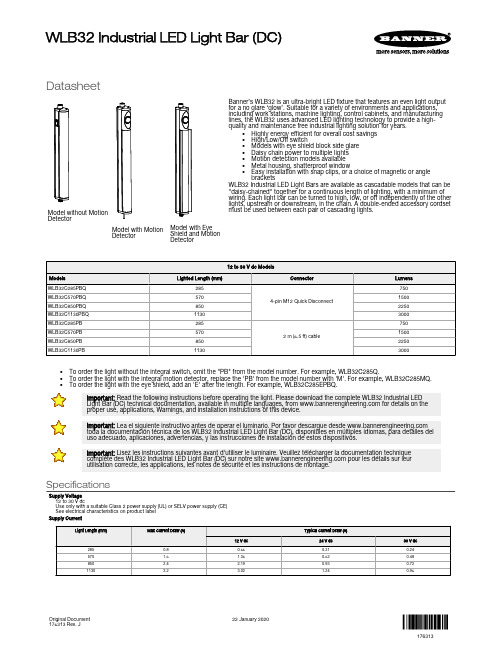
DatasheetModel without MotionDetectorModel with MotionDetectorModel with Eye Shield and Motion DetectorBanner’s WLB32 is an ultra-bright LED fixture that features an even light output for a no glare ‘glow’. Suitable for a variety of environments and applications,including work stations, machine lighting, control cabinets, and manufacturing lines, the WLB32 uses advanced LED lighting technology to provide a high-quality and maintenance free industrial lighting solution for years.•Highly energy efficient for overall cost savings •High/Low/Off switch•Models with eye shield block side glare •Daisy chain power to multiple lights •Motion detection models available •Metal housing, shatterproof window•Easy installation with snap clips, or a choice of magnetic or anglebracketsWLB32 Industrial LED Light Bars are available as cascadable models that can be "daisy-chained" together for a continuous length of lighting, with a minimum of wiring. Each light bar can be turned to high, low, or off independently of the other lights, upstream or downstream, in the chain. A double-ended accessory cordset must be used between each pair of cascading lights.•To order the light without the integral switch, omit the "PB" from the model number. For example, WLB32C285Q.•To order the light with the integral motion detector, replace the 'PB' from the model number with 'M'. For example, WLB32C285MQ.•To order the light with the eye shield, add an 'E' after the length. For example, WLB32C285EPBQ.Important: Read the following instructions before operating the light. Please download the complete WLB32 Industrial LED Light Bar (DC) technical documentation, available in multiple languages, from for details on the proper use, applications, Warnings, and installation instructions of this device.Important: Lea el siguiente instructivo antes de operar el luminario. Por favor descargue desde toda la documentación técnica de los WLB32 Industrial LED Light Bar (DC), disponibles en múltiples idiomas, para detalles deluso adecuado, aplicaciones, advertencias, y las instrucciones de instalación de estos dispositivos.Important: Lisez les instructions suivantes avant d'utiliser le luminaire. Veuillez télécharger la documentation technique complète des WLB32 Industrial LED Light Bar (DC) sur notre site pour les détails sur leur utilisation correcte, les applications, les notes de sécurité et les instructions de montage.SpecificationsSupply Voltage 12 to 30 V dcUse only with a suitable Class 2 power supply (UL) or SELV power supply (CE)See electrical characteristics on product label Supply CurrentWLB32 Industrial LED Light Bar (DC)Original Document 176313 Rev. J22 January 2020176313Supply Protection CircuitryProtected against reverse polarity and transient voltagesLight CharacteristicsColor: Daylight whiteColor temperature (CCT): 5000K (±300K)Lumen output: 750 (±5%) per foot, typical at 25 °C (77 °F)Luminous efficacy: 100 lumens/Watt typical at 24 V dc at 25 °C (77 °F)CRI: 85, typicalEye shield reduces lumens by about 25%LED LifetimeLumen Maintenance - L70When operating within specifications, output will decrease less than 30% after 50,000 hours.Push ButtonII = 100% light intensityI = 50% light intensityO = OffModels with Motion DetectionLight turns off after approximately 60 seconds without detecting motion.Range: 12 meters; ±45° field of viewStandby current: 170 µAConstructionAnodized aluminum housing; polycarbonate window and end caps; stainless steel mounting bracketsSpacing CriterionVertical: 1.22Horizontal: 1.32MountingSnap clips; optional magnetic mount or swivel bracket accessories available ConnectionsIntegral 4-pin Euro-style QD (4-pin connecting cordset required for QD models); or 2 m(6.5 ft) integral cable Environmental RatingIEC IP50Vibration and Mechanical ShockVibration 10-55 Hz 1.0 mm p-p amplitude per IEC60068-2-6Shock 15G 11 ms duration, half sine wave per IEC60068-2-27Operating Temperature–40 °C to +70 °C (–40 °F to +158 °F)Light output begins to decrease above 50 °C (122 °F) and will be approximately 65% of max intensity at 60 °C (140 °F) and 30% of max intensity at 70 °C (158 °F)Models with motion detection: –20 °C to +60 °C (–4 °F to +140 °F)Storage Temperature–40 °C to +70 °C (–40 °F to +158 °F)Test DataLM-79, LM-80, TM-21CertificationsE476617UL Recognized for easy installationin control cabinets.Application NoteWhen connecting cascadable lights in series it is important not to exceed themaximum current limitation of 4 AmpsMaximum length of light at 12 V dc: 1.4 m (4.6 ft)Maximum length of light at 24 V dc: 3.0 m (9.8 ft)Maximum length of light at 30 V dc: 3.1 m (10.2 ft)Spacing Criteria (SC)The spacing criteria is the fixture-spacing-to-mounting-height ratio and aids in laying out a pattern of fixtures. Multiply the spacing criteria by the mounting height to get the maximum fixture spacing that still provides even illumination (no shadowing between fixtures).Luminaire Spacing = SC × Height to Illuminated PlaneThe mounting height is the distance from the fixture to the surface you are lighting.Light Characteristics180°CD(candela)23019215311577383877115153192230170°160°150°140°130°120°110°100°90°80°70°60°50°40°30°20°10°0°Polar Candela DistributionIsolux PatternIlluminance at a DistanceVertical Angle:0° Vertical90° Horizontal150 lux125 lux100 lux75 lux50 lux25 lux10 lux5 lux50% max.candelaFigure 1. 285 mm Models - Tel: + 1 888 373 6767P/N 176313 Rev. J180°CD(candela)4603833072301537777153230307383460170°160°150°140°130°120°110°100°90°80°70°60°50°40°30°20°10°0°Vertical Angle:0° Vertical90° Horizontal300 lux250 lux200 lux150 lux100 lux50 lux25 lux10 lux50% max.candelaVertical Spread: 101.5°Horizontal Spread: 128.2°Vert.Horiz.Figure 2. 570 mm ModelsPolar Candela DistributionIlluminance at a DistanceVertical Spread: 102.7°Horizontal Spread: 130.1°Vert.Horiz.180°(candela)650542433325217108108217325433542650170°160°150°140°130°120°110°100°90°80°70°60°50°40°30°20°10°0°Illuminance at a DistanceVertical Angle:0° Vertical90° HorizontalFigure 3. 850 mm ModelsPolar Candela DistributionIsolux PatternIlluminance at a Distance600 lux500 lux400 lux300 lux200 lux100 luxMount height of 1 meter (1 m)50 lux25 lux50% max.candela180°CD(candela)870725580435290145145290435580725870170°160°150°140°130°120°110°100°90°80°70°60°50°40°30°20°10°0°Vertical Angle:0° Vertical90° HorizontalFigure 4. 1130 mm ModelsP/N 176313 Rev. J - Tel: + 1 888 373 67673Vertical Spread: 98.7°Horizontal Spread: 102.8°Vert.Horiz.150 lux 125 lux 100 lux75 lux 50 lux 25 lux10 lux 5 lux 50% max. candela180°C D (c a n d e l a )250208167125834204283125167208250170°160°150°140°130°120°110°100°90°80°70°60°50°40°30°20°10°0°Vertical Angle:0° Vertical 90° HorizontalFigure 5. 285 mm Models with Eye ShieldsPolar Candela DistributionIsolux PatternIlluminance at a DistanceVertical Spread: 83.5°Horizontal Spread: 97.0°Vert.Horiz.2211300 lux 250 lux 200 lux150 lux 100 lux 50 lux25 lux 10 lux 50% max.candela180°C D (c a n d e l a )50041733325016783083167250333417500170°160°150°140°130°120°110°100°90°80°70°60°50°40°30°20°10°0°Vertical Angle:0° Vertical 90° HorizontalFigure 6. 570 mm Models with Eye ShieldsPolar Candela DistributionIsolux PatternIlluminance at a DistanceMount height of 1 meter (1 m)450 lux 375 lux 300 lux225 lux 150 lux 75 lux25 lux 10 lux 50% max.candela180°C D (c a n d e l a )6305254203152101050105210315420525630170°160°150°140°130°120°110°100°90°80°70°60°50°40°30°20°10°0°Vertical Angle:0° Vertical 90° HorizontalFigure 7. 850 mm Models with Eye Shields - Tel: + 1 888 373 6767P/N 176313 Rev. JVertical Spread: 83.8°Horizontal Spread: 124.8°Vert.Horiz.600 lux 500 lux 400 lux300 lux 200 lux 100 lux50 lux 25 lux 50% max. candela180°C D (c a n d e l a )8206835474102731370137273410547683820170°160°150°140°130°120°110°100°90°80°70°60°50°40°30°20°10°0°Vertical Angle:0° Vertical 90° HorizontalFigure 8. 1130 mm Models with Eye ShieldsWiringP/N 176313 Rev. J - Tel: + 1 888 373 67675DimensionsMotion Detector and/or Eye Shield ModelsSpecific to models with shieldAccessories - Tel: + 1 888 373 6767P/N 176313 Rev. JP/N 176313 Rev. J - Tel: + 1 888 373 67677Banner Engineering Corp. Limited WarrantyBanner Engineering Corp. warrants its products to be free from defects in material and workmanship for one year following the date of shipment. Banner Engineering Corp. will repair or replace, free of charge, any product of its manufacture which, at the time it is returned to the factory, is found to have been defective during the warranty period. This warranty does not cover damage or liability for misuse, abuse, or the improper application or installation of the Banner product.THIS LIMITED WARRANTY IS EXCLUSIVE AND IN LIEU OF ALL OTHER WARRANTIES WHETHER EXPRESS OR IMPLIED (INCLUDING, WITHOUT LIMITATION, ANY WARRANTY OF MERCHANTABILITY OR FITNESS FOR A PARTICULAR PURPOSE), AND WHETHER ARISING UNDER COURSE OF PERFORMANCE, COURSE OF DEALING OR TRADE USAGE.This Warranty is exclusive and limited to repair or, at the discretion of Banner Engineering Corp., replacement. IN NO EVENT SHALL BANNER ENGINEERING CORP. BE LIABLE TO BUYER OR ANY OTHER PERSON OR ENTITY FOR ANY EXTRA COSTS, EXPENSES, LOSSES, LOSS OF PROFITS, OR ANY INCIDENTAL, CONSEQUENTIAL OR SPECIAL DAMAGES RESULTING FROM ANY PRODUCT DEFECT OR FROM THE USE OR INABILITY TO USE THE PRODUCT, WHETHER ARISING IN CONTRACT OR WARRANTY, STATUTE, TORT, STRICT LIABILITY, NEGLIGENCE, OR OTHERWISE.Banner Engineering Corp. reserves the right to change, modify or improve the design of the product without assuming any obligations or liabilities relating to any product previously manufactured by Banner Engineering Corp. Any misuse, abuse, or improper application or installation of this product or use of the product for personal protection applications when the product is identified as not intended for such purposes will void the product warranty. Any modifications to this product without prior express approval by Banner Engineering Corp will void the product warranties. All specifications published in this document are subject to change; Banner reserves the right to modify product specifications or update documentation at any time. Specifications and product information in English supersede that which is provided in any other language. For the most recent version of any documentation, refer to: .For patent information, see /patents. - Tel: + 1 888 373 6767P/N 176313 Rev. JFCC Part 15 and CAN ICES-3 (B)/NMB-3(B)This device complies with part 15 of the FCC Rules and CAN ICES-3 (B)/NMB-3(B). Operation is subject to the following two conditions:1.This device may not cause harmful interference, and2.This device must accept any interference received, including interference that may cause undesired operation.This equipment has been tested and found to comply with the limits for a Class B digital device, pursuant to part 15 of the FCC Rules and CAN ICES-3 (B)/NMB-3(B). These limits are designed to provide reasonable protection against harmful interference in a residential installation. This equipment generates, uses and can radiate radio frequency energy and, if not installed and used in accordance with the instructions, may cause harmful interference to radio communications. However, there is no guarantee that interference will not occur in a particular installation. If this equipment does cause harmful interference to radio or television reception, which can be determined by turning the equipment off and on, the user is encouraged to try to correct the interference by one or more of the following measures:•Reorient or relocate the receiving antenna.•Increase the separation between the equipment and receiver.•Connect the equipment into an outlet on a circuit different from that to which the receiver is connected.•Consult the manufacturer.Mexican ImporterBanner Engineering de Mèxico, S. de R.L. de C.V.David Alfaro Siqueiros 103 Piso 2 Valle orienteSan Pedro Garza Garcia Nuevo Leòn, C. P. 6626981 8363.2714© Banner Engineering Corp. All rights reserved。
LED补光灯使用说明

LED 补光灯使用说明
一、 实物连接图
连
接
至
补
光
灯
BNC 三通头连接至识别
器等设备
12V 电源
适配器
连接至220V 电源
连接示意图
实物连接图
二、 各部分名称和功能
1.模式选择按钮
(SW2、SW4)2.显示值改变按钮
(SW1、SW3) 5.显示值改变指示灯(D23~D16)4.模式选择指示灯(D27~D24)3.光感开关调节旋钮
(W1)
如上图所示:
1. 模式选择按钮(SW2、SW4,即上、下箭头键),通过按SW2、SW4,即可选择LED 补光灯工作模式。
2. 显示值改变按钮(SW1、SW3,即+、-键),通过按SW1、SW3,即可调节对应模式下的显示值。
3. 光感开关调节旋钮(W1),通过旋转W1,即可控制LED 补光灯在不同暗度下开、关。
4. 模式选择指示灯(D27~D24)
5. 显示值改变指示灯(D23~D16)
三、 LED 补光灯设置
说明:D27~D16指示灯亮时为1,灭时为0,具体设置如下表所示。
LED灯使用说明书

Agradecemos su compra!Por favor, lea el manual de instrucciones antes de la instalación y consérvelo a mano para consultas futuras.Luminaria con disipador térmico de aluminio fundido de alta pureza, alta luminosidad, chip SMD Nichia, con un driver Sosen de corriente constante. Diseño del PCB LED para media y gran altura en industria: producción, almacenes diáfanos con estanterías a media altura, talleres, gasolineras, centros comerciales, mercados, peajes de autopistas y aplicaciones similares.ProblemaPosible CausaSolucionesLED no funciona El cable de red no está conectado Conecta el cable de red.El enchufe está sueltoConéctelo firmemente a la toma de corriente. El driver del LED tiene una avería Reemplace el driver con uno nuevo.El chip LED está dañado Puede ser reparado sólo por Venalsol. La luz LED se enciende y apaga La salida del driver es anómala Reemplace el driver por uno nuevo.El chip LED tiene una averíaPuede ser reparado sólo por Venalsol.Venalsol garantiza sus productos, dentro de las condiciones generales de suministro, siempre que se trate de un defecto de fabricación o materiales por un período de cinco años a partir de la fecha de compra. La garantía consiste en la reparación/sustitución de las partes o conjuntos que se consideren defectuosos. No se aplicará por lo tanto a los artículos que presenten daños como consecuencia de no haber seguido correctamente las instrucciones de uso, o cuando la instalación haya sido realizada por personal no especializado. Así mismo, quedan excluidos los daños ocasionados por uso indebido del aparato y averías producidas en el transporte.Para realizar una reclamación de garantía, es necesario notificarlo por escrito a su vendedor, aportar factura de compra y cumplir con los demás requisitos de garantía. Siempre será necesario la devolución del producto averiado con su original placa identificativa de Venalsol Smart Light y su número de serie. Los costes de transporte están excluidos.1. La decisión de si el producto es defectuoso será tomada por Venalsol, que comprobará el mal funcionamiento del producto. SiVenalsol comprueba que el producto es defectuoso, decidirá si se ha de reparar o reemplazar por uno nuevo. Venalsol se reserva el derecho de utilizar productos nuevos o reparados en el proceso de reparación o sustitución del producto en garantía. El producto que se haya reparado o reemplazado, se garantizará durante el período de garantía original que le quede. El coste de personal y el coste de la maquinaria necesaria para la sustitución queda excluido. La responsabilidad total de Venalsol respecto al producto defectuoso estará siempre limitada al dinero pagado por el comprador por ese producto originalmente.2. En caso de solicitud de un producto en buen estado, previo al envío del producto defectuoso, con el fin de facilitar las labores de sustitución, Venalsol podrá aceptar suministrarlo y éste será facturado. Esta factura será abonada si procede, una vez sea recibido y verificado el producto supuestamente averiado. De no cumplir los requisitos de garantía, o no recibirse el material averiado, pasados 60 días de la reposición previa, se procederá al cobro de la factura.La garantía no cubrirá las siguientes circunstancias:1. Daños causados por fuerza mayor como guerras, revueltas, sabotajes, ciclones, terremotos, inundaciones explosiones, incendios, etc.2. Daños causados por uso inapropiado durante el período de entrega, defectos causados por su mal uso, tratamiento erróneo o destrucción de la maquinaria.3. Desmontaje, modificación o mantenimiento inapropiado productos reparados sin autorización del proveedor.4. Daños causados por el comprador o instalador usando cableado de baja calidad o otros componentes no compatibles con el producto.5. Esta garantía no es válida si el producto es usado para propósitos diferentes para los que está originalmente diseñado.Lea detenidamente las instrucciones antes de comenzar a utilizar el producto.50W - 100W - 150W – 200WVenalsol Smart Light S.L.C/ Garbí nº15. - Polígono Industrial Palma de Gandía - 46724 - Palma de Gandía Valencia (España) - Atención al cliente: +34 962 808 219 *****************< VER FICHA TÉCNICATodos los derechos reservados - Copyright © 2017Manual de instrucciones1. Desconecte el suministro de energía antes de la instalación o del mantenimiento de la luminaria.2. Es estrictamente obligatorio conectar el cable de tierra (Amarillo/Verde) con el conexionado de tierra de la instalación.3. No toque la fuente de alimentación cuando la lámpara esté en funcionamiento.4. Para evitar daños, descargas eléctricas o incendios, no desmonte o reemplace la lámpara (PCB CHIP LED).5. Para evitar daños, caídas, descargas eléctricas o incendios, por favor no modifique o reemplace los accesorios originales porotros que no lo sean, sin consultar y estar autorizado por Venalsol con anterioridad.6. Sólo personal cualificado puede realizar la sustitución o instalación de la luminaria y asegúrese de que sigue las instruccionesdel manual. Si la instalación no se realiza adecuadamente, puede causar caídas, descargas eléctricas, incendios u otros daños.7. Desconecte el suministro de energía si sale humo o produce olor, ya que podría producirse un incendio o descarga eléctrica.8. Consulte a personal cualificado para la inspección y mantenimiento de la lámpara.9. Si el cableado propio de la luminaria está dañado, sólo puede ser reemplazado por Venalsol.Normativa aplicableHa pasado los test y verificaciones necesarios para la obtención del Marcado CE. Este producto cumplecon los estándares de aplicación sobre Baja Tensión (LVD) 2014/35/EU: EN60598-1:2015, EN60598-2-24:2013, EN60598-2-1:1989, EN62031:2008, EN62471:2008, EN62493:2010 y CompatibilidadElectromagnética (EMC)2014/30/EU: EN61000-3-2:2014, EN61000-3-3:2013, EN61547:2009,EN55015:2013.Este símbolo indica que el producto al final de su vida útil deberá eliminarse por separado de los demásdesechos, puesto que se identifica como un aparato de uso eléctrico o electrodoméstico según el RealDecreto 208/2005. Por lo tanto, al final del uso, deberá hacerse cargo de entregar el producto a uncentro de recogida selectiva o a un gestor de residuos autorizado. Venalsol está registrado en elRegistro Nacional de Aparatos Eléctricos y Electrónicos con número de inscripción registral 3493 y seencuentra adherida a un Sistema de Gestión de Residuos de Aparatos Eléctricos y Electrónicos para losproductos con la categoría de "aparatos de alumbrado".Las luminarias LED Venalsol son respetuosas con el Medio Ambiente. No contienen mercurio y loscomponentes electrónicos utilizados cumplen con lo establecido en la normativa RoHS de transposiciónal Real Decreto 208/2005.Parámetros TécnicosEspecificaciones del producto 50W 100W 150W 200WVoltaje de entrada AC200-277V 50/60Hz Clase I ( Necesita toma de tierra )CRI Ra70Angulo del Haz de Luz 65x120º, 30x60º, 30º, 15º, 120ºClasificación IP IP66Dimensiones 300x240x69mm 335x295x71mm 375x320x75mm 400x345x78Peso neto de la luminaria 2.2 ±0.3kg 3.5 ±0.3kg 4.0 ±0.3kg 5.1 ±0.3kgFactor de potencia >0.90Vida útil ≥50000Hrs (LM70@35°C)Temperatura de funcionamiento -30 ~ +50°CHumedad de funcionamiento 15% ~ 90%RHTemperatura de almacenaje -40 ~ +70°CA. Dimensiones (mm.) e instalación mediante fijación ajustable50W 100W 150W 200WA 300 335 375 400B 240 295 320 345C 69 71 75 78D 215 265 290 320E 90 120 120 120F 120 165 170 180B. Dimensiones e instalación mediante posteDiagrama de cableado。
led 仪器操作规程

led 仪器操作规程LED 仪器操作规程第一章总则第一条为保证 LED 仪器的正常运行和使用安全,规范操作行为,制定本操作规程。
第二章仪器的使用范围与限制第二条 LED 仪器适用于 LED 照明产品的测试、分析和质量控制。
第三条 LED 仪器只能接触到经允许使用的部位,禁止随意拆卸和更换组件。
第四条未经过专业培训人员的授权,禁止擅自操作LED 仪器。
第三章操作准备第五条操作前需仔细阅读相关仪器的操作手册,了解仪器使用的基本原理、功能和操作流程。
第六条在操作前,需要检查仪器是否正常工作,保证仪器的安全可靠性。
第七条操作前,应确保操作场所具备良好的通风条件,确保操作人员的身体健康与安全。
第四章操作程序第八条操作人员应佩戴合适的防护设备,如眼镜、口罩、防静电手套等。
第九条操作人员应按照操作手册的要求,正确设置仪器参数和连接测试设备。
第十条操作人员应根据待测试的 LED 灯具的特性和要求,选择合适的测试方法。
第十一条操作人员应按照操作手册的要求,启动仪器并进行测试。
第十二条操作人员在测试过程中应注意仪器的运行状态,及时处理可能产生的故障。
第十三条操作人员在使用仪器过程中,不得进行任何损坏仪器的行为,保证仪器的完好性和长期使用。
第五章操作事项第十四条操作人员在操作中需保持注意力集中,防止疲劳和粗心大意。
第十五条操作人员在操作过程中,应严格按照操作手册进行操作,不得随意更改参数或程序。
第十六条操作人员在操作过程中,应注意观察仪器的指示灯和显示屏,确保测试结果的准确性。
第十七条操作人员在操作过程中,应注意保持试验样品的干燥、清洁和无污染。
第六章操作结束第十八条操作结束后,应关闭仪器电源,并按照操作手册的要求进行仪器的维护和保养。
第十九条操作结束后,应清理现场,保持仪器和操作台面的清洁和整齐。
第二十条操作人员应做好相关记录,包括实验数据、问题和解决办法等,以备后续分析和总结。
第七章安全注意事项第二十一条使用 LED 仪器时,应确保操作人员具备必要的安全知识和技能。
LED 灯管使用说明
深圳华朗电子有限公司
SHenZHen Hualang Electronics Co. , Ltd.
使用说明书
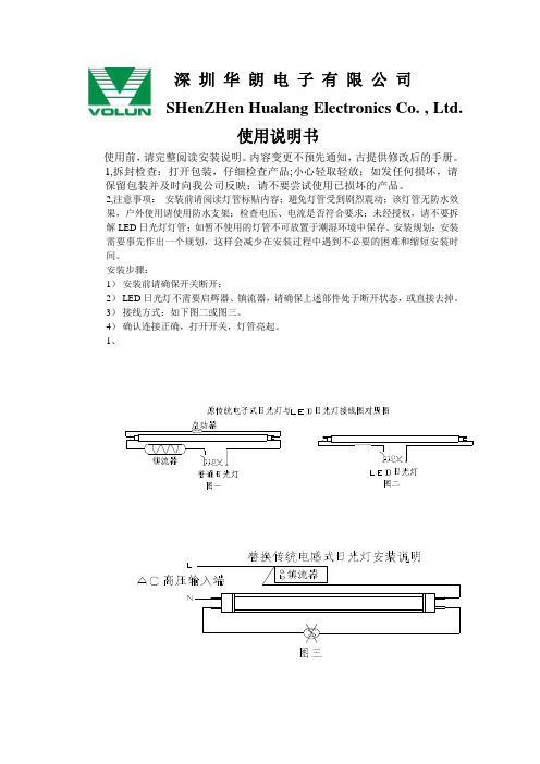
使用前,请完整阅读安装说明。
内容变更不预先通知,古提供修改后的手册。
1,拆封检查:打开包装,仔细检查产品;小心轻取轻放;如发任何损坏,请保留包装并及时向我公司反映;请不要尝试使用已损坏的产品。
2,注意事项:安装前请阅读灯管标贴内容;避免灯管受到剧烈震动;该灯管无防水效果,户外使用请使用防水支架;检查电压、电流是否符合要求;未经授权,请不要拆解LED日光灯灯管;如暂不使用的灯管不可放置于潮湿环境中保存。
安装规划:安装需要事先作出一个规划,这样会减少在安装过程中遇到不必要的困难和缩短安装时间。
安装步骤:
1)安装前请确保开关断开;
2)LED日光灯不需要启辉器、镇流器,请确保上述部件处于断开状态,或直接去掉。
3)接线方式:如下图二或图三。
4)确认连接正确,打开开关,灯管亮起。
1、。
LED图文32双使用说明书
LED图文使用说明一、特点及技术规格●特点1.LED1图文条形屏控制卡是采用单片机控制,有时钟显示,亮度控制,定时开机关机,分时显示节目。
2.可以分区域显示,显示方式有左滚、上滚、上移、下移、左移、右移、左展、右展、立即。
3.可以制作动画,并能对动画速度设置。
4.采用FLASH存储器、不用电池能长时间保持存储内容。
5.通过RS232接口向控制版输入显示内容、校准时间。
6.编辑软件易学易用。
7.采用图形格式保存,能选择文字字体和大小。
8.可以编辑时钟显示内容和显示位置。
●一般技术规格1.电源:控制卡5V。
2.串口形式:RS232,串口波特率为9600,串口数据位为8位,串口校验为无。
3.存储内容:存储器用W29C020,下载地址可以到262,143字节,当选择24号字和字型为规则时保存1800个汉字。
当小于24号字时可以多存。
二、软件使用1.安装:打开安装盘,输入setup启动安装,然后按屏幕提示要求完成安装过程。
2.设置:单击菜单中的(设置)项,密码是168,按显示屏规格输入横向点数和纵向点数,再按确定。
3.新建:单击菜单中的(文件)、(新建)项。
4.添加节目:单击节目管理工具栏中添加节目按钮。
如果长时间显示或这个节目只有时钟窗口时,请选择立即计时播放、输入播放时间。
如果上午或下午显示这个节目,请选择分时允许播放。
显示节目名称栏可以修改节目名称。
5.添加显示窗口:单击节目管理工具栏中添加窗口按钮。
6.设定显示窗口大小和位置:按显示窗口栏中上、下箭头。
7.添加显示内容:单击显示内容工具栏中打开按钮,选择添加文件,这个文件自动分解成页,一页长度是显示窗口栏中长度显示。
如页数大于255时把这个文件分解。
这个文件显示特技在显示方式栏中修改。
最多添加50个文件。
双击这个文本文件就可以显示和修改。
遇到空格符为空半角字宽,遇到回车返回符为结束这行(左滚空2个汉字宽)。
8.亮度控制:单击菜单中的(亮度)项。
按小时输入显示亮度。
GP-2000C 使用说明书
G P-2000C使用说明书一、概述:GP-2000C型LED工业射线底片观片灯是我公司针对JB/T4730-2005《承压设备无损检测》和GB/T 19802-2005《工业射线照相底片观片灯》最新标准研制的新产品。
GP-2000C 观片灯综合了国内外工业观片灯的所有优点,采用了最先进的数字式电子技术和最新的超高亮度大功率LED光源,克服了传统观片灯亮度低、对比度差、均匀度低、衰减快、寿命短等缺点,外形美观大方,人性化操作,必定将成为您评片上的最好帮手。
二、产品特点:1、GP-2000C采用全数字式控制方式,与机械式控制的观片灯相比,工作更可靠,性能更稳定,使用寿命更长;调光更灵活,更便捷,更精确,只需轻轻按几下,就可调出自己所需要的光。
2、GP-2000C可根据光的强弱,显示底片的黑白密度值;调光时也可根据黑白密度值,快捷地跳出底片所需要的光。
这在国内尚属首例。
3、GP-2000C 具有全新的实时温度采集系统,实现了对光源的实时保护。
用户可通过按下“存储”键并保持2秒以上,面板上的数码管将显示出其内部温度。
当观片灯经常触及部位的外壳温度达到60度时,观片灯自动将光的亮度调到最低,同时面板上数码管闪烁“H H”符号。
当观片灯的温度降到正常后,自动恢复到原来的亮度,面板上数码管的显示也自动恢复到原来的黑白密度值。
4、革命性的采用了美国最先进的进口晶架、大晶片等白光光源技术,特身定做的超大功率LED光源,真正的冷光源,超高亮LED,观察屏最高亮度达到125,000cd/m2 (388,000Lux),可清晰地观察到在5.0D以上黑度底片上的微小缺陷,均匀度达到0.9以上。
5、观察屏材料采用日本三凌丽阳株式社生产的亚克力板,具有超越玻璃的透光性,良好的漫散射性能,并且持久耐用,不变形,不变色。
6、根据人眼生理学特点,限定LED的色温在7000K,不刺眼,即使长时间地观看,眼睛也不易疲劳。
7、采用PWM低压数字电子方式连续调光技术,能够在5%-100%超宽范围调节亮度,让您可以根据需要任意调节。
观片灯操作规程

风险提示:
人员风险:操作人员都应经过专业培训,并持有国家主管部门颁发的Ⅱ级或Ⅱ级以上的射线检验人员资格证书。
操作
顺序
操作项目、内容、方法及要求
存在风险
风险控制措施
应用辅助工具用具
1
使用前准备:
1.1
按要求接入电源(220V、50Hz),检查电路是否连接正确、可靠。电网电压是否符合要求。
手动模式:按“向下”和“向上”按钮调节观片灯亮度,亮度完成后自动记忆,不感应胶片的存在。
光亮刺伤眼睛
3
关闭电源
应急处置程序:
人员发生机械伤害,第一发现人员应立即停运致害设备,现场视伤势情况对受伤人员进行紧急包扎处理。如伤势严重,应立即拨打120求救。
人员发生触电事故,第一发现人应立即切断电源,视触电者伤势情况,采取人工呼吸、胸外心脏挤压等方法现场施救。如伤势严重,应立即拨打120求救。
电击风险
电源线路如有破损立即更换
2
打开电源开关
2.1
接通电源后,观片灯正常点亮(出厂时为最低亮度1.0)
2.2
按模式键,可切换自动模式和手动模式。
2.3
当模式灯亮为自动模式,灯灭为手动模式。长按模式键显示仪器内部温度。
2.4
自动模式:放上胶片,按“向下仪器自动降为最低亮度。
- 1、下载文档前请自行甄别文档内容的完整性,平台不提供额外的编辑、内容补充、找答案等附加服务。
- 2、"仅部分预览"的文档,不可在线预览部分如存在完整性等问题,可反馈申请退款(可完整预览的文档不适用该条件!)。
- 3、如文档侵犯您的权益,请联系客服反馈,我们会尽快为您处理(人工客服工作时间:9:00-18:30)。
xxxx检测器材有限公司
地址:
xxxxxx开发区邮编:272071
电话:传真:
一、仪器概述
LK-LED32型高亮度LED观片灯是我公司针对JB/T4730-2005《承压设备无损检测》和GB/T 19802-2005《工业射线照相底片观片灯》最新标准研制的新产品。该观片灯采用了大功率LED光源,具有超强的亮度,满足了用户观察高黑度胶片的需要,而且具有功耗低、重量轻、无辐射等优点。独具匠心的设计使其造型美观、操作更加人性化。铝合金外壳实现了整机散热,使仪器能够长时间稳定工作。独具慧眼的您选择了这款观片灯,肯定会给你的工作带来极大的方便。
二、主要技术参数
1、电源:
AC220V(±10%)/50Hz1
2、最大亮度:3200LUX
3、整机功耗:
约160W
4、观测黑度:
大于
4.5D
5Байду номын сангаас外形尺寸:500×140×
68.4(mm)
6、窗口尺寸:253×68(mm)
7、整机重量:
2.7kg
三、主要构成
LK-LED32型高亮度观片灯主要由光源、散热系统、电源及调光系统、窗口和外壳五部分组成。2四、操作说明
说明书1根1个2个1份用户xx
一、用户购买本公司产品后,先按装箱单核检仪器及配件是否齐全,核对后请认真阅读此使用手册,在了解了该仪器的使用操作后再对该仪器进行实际的应用。5二、本公司产品从用户购买之日起负责保修壹年。若出现质量问题(非保修件除外),请与本公司仪器技术服务中心联系。
三、凡因用户自行拆装本公司产品、因运输、保管不当或未按产品说明书正确操作造成产品损坏,本公司将有权不予以保修。
五、注意事项
1、电源良好接地,以确保使用安全。3
2、请注意保护观片窗口,以免误判评片。
3、仪器若发生故障请勿擅自拆卸并试图维修本产品。请及时与0537—联系,或将仪器发回我公司修理。
六、装箱清单
LK—LED32型xxLED观片灯
脚踏开关
挡光板
放大镜1xx1支1个个4电源线
挡片条
保险丝(2A)
xx合格证
1、使用前首先确认电源开关处于“关”状态,然后连接电源线。
2、打开电源开关,转换开关处于“关”时为手动调光模式;转换开关处于“开”时,接入脚踏开关,为脚踏开关模式。
a)手动调光模式:
旋转亮度调光旋钮,亮度可在10%至100%范围内无级调节。
b)脚踏开关模式:
接入脚踏开关后,踏之可达到调光旋钮预置亮度。如需调整亮度,应踏下脚踏开关并调节调光旋钮。
四、请按照使用说明正确使用,如发现异常,请停止使用并请及时与我公司联系。
谢谢合作!