ALIF两线电子式无触点磁性开关特色说明
磁敏开关的原理和应用场合

磁敏开关的原理和应用场合1. 磁敏开关的原理磁敏开关(Reed开关)是一种基于磁场感应原理的电子开关,由Reed线圈和铁磁性材料组成。
当外部磁场作用于磁敏开关时,铁磁性材料会受到磁场的吸引,导致Reed线圈内的金属片闭合或断开,实现电路的开关。
2. 磁敏开关的工作原理磁敏开关内部包含两个金属片,当金属片被磁场吸引时,会闭合线圈,电路通电;当磁场消失时,金属片会恢复原位,打开线圈,电路断电。
这种开关结构简单且可靠,无接触式操作,因此在许多应用场合中被广泛使用。
3. 磁敏开关的应用场合3.1 安防系统磁敏开关常用于安防系统中,如门窗报警系统。
将磁敏开关连接到门窗等物体上,当门窗关闭时,磁敏开关闭合,电路通电,系统处于正常状态;一旦门窗打开,磁敏开关断开,电路断电,触发报警器发出警报。
3.2 汽车电子磁敏开关广泛应用于汽车电子领域。
例如,用于发动机的点火系统中,磁敏开关监测发动机转速,控制点火时机。
同时,在车辆的防盗系统中,磁敏开关能够检测车窗和车门的状态,一旦检测到异常,会触发报警系统。
3.3 工业自动化在工业自动化领域,磁敏开关也得到广泛应用。
例如,在流水线上用于检测物体的位置和运动状态,通过安装磁敏开关,可以实现精确的物体检测和位置控制。
3.4 电子游戏磁敏开关也常用于电子游戏中的控制设备,如游戏手柄。
通过安装磁敏开关,可以实现游戏手柄上按键的控制和操作。
4. 磁敏开关的优势•简单易用:磁敏开关结构简单,安装方便,可靠性高。
•零接触:磁敏开关无接触式操作,无需担心磨损和寿命问题。
•高灵敏度:磁敏开关对磁场的感应灵敏度高,能够快速响应。
5. 磁敏开关的注意事项•避免过大磁场:长时间暴露在强磁场中会损坏磁敏开关,因此在使用过程中应避免过大的磁场。
•防水防尘设计:根据具体场合的需求,选择合适的磁敏开关进行防水防尘设计,以保证其正常工作。
6. 结论磁敏开关作为一种基于磁场感应原理的电子开关,具有结构简单、可靠易用的特点,在安防系统、汽车电子、工业自动化和电子游戏等领域得到广泛应用。
两线i3感应器及风格D触发循环的2W-MOD2模块说明书

NOTE: If two–wire i3 detectors are used in conjunction with a style D initiating circuit, the 2W–MOD2 must be used to provide that capability. Ground fault on a mod-ule’s two-wire loop can be indicated at a control panel if the control panel is capable of ground fault detection on the power supply to the module and meets NFPA 72 ground fault indication requirements for initiating device circuits. The installer must verify that capability.Figure 3. Module LED modes:Power on. Detectors on loop do not havecommunication capability.Power on. One or more detectors on loop have communication capability.Power not applied or module not operating properly.Detector on loop in alarm.One or more detectors out of sensitivity or in Freeze Trouble.Detectors on loop not in alarm, maintenance or Freeze Trouble.Loop wiring fault.EZ Walk Test mode.Loop wiring normal.ONBlink 1 sec. ON and 1 sec. OFFOFFONBlink 1 sec. ON and 1 sec. OFFOFF ONBlink 0.5 sec. ON and 0.5 sec. OFF OFFGREEN LEDRED LEDYELLOW LEDLED COLORSTATUS CONDITIONThe module has loop trouble restoration detection. If theloop trouble (open loop) doesn’t exist any more, the mod-ule will restore to standby condition with a maximum delay of 1 minute. There is no delay in loop trouble detection.If an alarm occurs while the module is indicating mainte-nance, the alarm will supercede maintenance.If the green LED remains ON (no blinking) three minutes af-ter applying power, it means that the module has determined that no detector on its loop has communication capability. In this condition, the detectors are still capable of initiating alarm and loop trouble at the module. However, maintenance and freeze trouble, will not be indicated at the module, and EZ walk test will not be available. If i 3 detectors are installed on the loop, verify wiring and system operation.Before InstallingThis information is included as a quick reference installa-tion guide. Refer to the control panel installation manual for detailed system information. If the modules will be in-stalled in an existing operational system, inform the opera-tor and local authority that the system will be temporarily out of service. Disconnect power to the control panel before installing the modules.NOTICE: This manual shall be left with the owner/user of this equipment.General DescriptionThe 2W-MOD2 allows a control panel to receive a “need for maintenance” signal from two–wire i3 series smoke detec-tors, model numbers 2W–B, 2WT–B, 2WT A–B, and 2WTR–B. The module uses a form C zone relay to initiate “out of sen-sitivity” and “freeze trouble”, a form A zone alarm relay and a second form A zone relay to indicate loop fault (see Figure 1). An EZ Walk T est puts all detectors on the loop into a Walk T est mode for easy verification of detector loop wiring. Figure 1:Condition Maintenance relay (form C) Alarm relay (form A) Loop trouble relay (form A)Normal OFF Open Close Loop troubleOFF Open Open Maintenance/Freeze trouble ON Open Close Loop trouble andON Open Open Maintenance/Freeze trouble AlarmOFF CloseN/A Alarm and loop troubleOFF Close N/A Alarm and Maintenance/Freeze OFFCloseN/AtroubleTerminal Location Terminal 7 – N.O. Relay connected Relay connected between Terminal 8 – Common between terminals terminals 10 and 12Terminal 9 – N.C.10 and 11S0236-00Figure 2. Module front view:Green LED Red LED Yellow LED EZ Walk-Test PushbuttonS0218-00Three LED’s on the module provide a local visual indica-tion of the module status(es).The maintenance module allows two-wire smoke detectors to be used on any electrically compatible four-wire control panel.D500-46-001I56-2174-003INSTALLATION AND MAINTENANCE INSTRUCTIONS3825 Ohio Avenue, St. Charles, Illinois 601741-800-SENSOR2, FAX: 630-377-6495Loop Test/Maintenance ModuleModel: 2W-MOD2SeriesD500-46-00 4 I56-2174-003©2006 System SensorSystem Sensor warrants its enclosed product to be free from defects in materials and workmanship under normal use and service for a period of three years from date of manufacture. System Sensor makes no other express warranty for the enclosed product. No agent, representative, dealer, or employee of the Company has the authority to increase or alter the obligations or limitations of this Warranty. The Company’s obliga-tion of this Warranty shall be limited to the replacement of any part of the product which is found to be defective in materials or workman-ship under normal use and service during the three year period com-mencing with the date of manufacture. After phoning System Sensor’s toll free number 800-SENSOR2 (736-7672) for a Return Authorization number, send defective units postage prepaid to: System Sensor, Returns Specifications:ElectricalMechanicalSupply Voltage - Min.8.5 Volts (Power limited)Height: 4.5 inches Max. 30 Volts (Power limited) Width: 4.0 inches Max.Ripple Voltage: 30% of applied voltageDepth: 1.25 inches Max. Standby Current: 30mA (12 detectors on loop) Weight: 0.5 poundMax. Alarm Current: 90mA(Includes packaging Alarm Contact Ratings: 0.5 Amp @ 36 V DC, Resistivematerials)Maintenance Contact Ratings: 2 Amp @ 30 V DC, Resistive Min. Reset Voltage: 6 Volts Min. Reset Time:0.3 sec.Operating T emperature Range: 14°F to 122°F (-10°C to 50 °C)Operating Humidity Range: 0 to 95% RH non-condensing Storage T emperature Range: –4°F to 158°F (–20°C to 70 °C)Initial Communication Cycle: 2-6 minutes after power-up or panel reset EZ Walk T est Available: 6 minutes after power-up or panel reset2-wire compatibility Min. loop voltage: 10 Volts Max. loop voltage: 11.5 Volts Max. loop resistance: 50 ohm Max. loop ripple:1 Vpp Max. Loading Capacitance: 0.01 mF Max. Alarm current: 40 mA Max. Reset Voltage: 0.3 V Alarm Delay: NoMin. Alarm reset time: 0.3 sec.Max. normal load current: 1.25 mA Zone T ype: StandardEOL Device: 3.9 K Ω (0.25W , 5%)Loop style:B, D Compatibility/Zone identifier: AMax. detectors per zone: Models 2W–B and 2WT–B: 12 Model 2WTR–B: 1 Model 2WTA–B: 1N OTE: When used with the RRS–MOD reversal relay/synchroniza-tion module and the 2W–MOD2, a maximum of 12 2WTA–B detec-tors are allowed per zone.FCC StatementThis device complies with part 15 of the FCC Rules. Operation is subject to the following two conditions: (1) This device may not cause harmful interference, and (2) this device must accept any interference received, including interference that may cause undesired operation.NOTE: This equipment has been tested and found to comply with the limits for a Class B digital device, pursuant to Part 15 of the FCC Rules. These limits are designed to pro-vide reasonable protection against harmful interference in a residential installation. This equipment generates, uses and can radiate radio frequency energy and, if not installed and used in accordance with the instructions, may cause harmful interference to radio communications. However, there is no guarantee that interference will not occur in a particular installation. If this equipment does cause harmful interference to radio or television reception, which can be determined by turning the equipment off and on, the user is encouraged to try to correct the interference by one or more of the following measures: – Reorient or relocate the receiving antenna. – Increase the separation between the equipment and receiver. – Connect the equipment into an outlet on a circuit different from that to which the receiver is connected. – Consult the dealer or an experienced radio/TV technician for help.Three-Year Limited WarrantyDepartment, RA #__________, 3825 Ohio Avenue, St. Charles, IL 60174. Please include a note describing the malfunction and suspected cause of failure. The Company shall not be obligated to replace units which are found to be defective because of damage, unreasonable use, modi-fications, or alterations occurring after the date of manufacture. In nocase shall the Company be liable for any consequential or incidental damages for breach of this or any other Warranty, expressed or implied whatsoever, even if the loss or damage is caused by the Company’s negligence or fault. Some states do not allow the exclusion or limita-tion of incidental or consequential damages, so the above limitation orexclusion may not apply to you. This Warranty gives you specific legal rights, and you may also have other rights which vary from state to state.I56-2174-003able to detect alarm and wiring fault from the 2-wire loop.NOTE: If an alarm occurs on the 2W-MOD2 zone beforethe 2W–MOD2 has completed its power–up sequence, the module’s green LED will remain on. T o reset this condition, the system must be reset and the module must be allowed to complete its power–up sequence.When using the RRS-MOD with model 2WTA-B, do not mix the 2WTA-B with other model smoke detectors and dry con-tact closure devices, including mechanical heat detectors, manual pull stations and waterflow switches. Such mixing can cause a direct short on the auxiliary power terminals, damaging the control panel’s internal circuitry and/or dam-age devices connected to the initiating device circuit.EZ Walk TestThe 2W-MOD2 has a push button for EZ Walk T est mode (see Figure 2.). The EZ Walk T est feature is available 6 min-utes after power-up or panel reset. If the push button is pressed momentarily the module will activate EZ Walk T est for five minutes. All detectors on the loop should enter EZ Walk T est mode. See i3 detector manual for detector re-sponse in EZ Walk T est mode.NOTE: EZ Walk T est cannot be initiated if the Green LED is not blinking.If the 2W-MOD2 is in normal condition (Green LED blink-ing) and pressing the push button does not initiate EZ Walk T est, wait one minute and try again.At the end of the five minute period, the module will ter-minate EZ Walk T est and the yellow LED will stop blink-ing. The EZ Walk T est period can be extended by pressing the push button a multiple number of times. For example, pressing the push button N times will result in a Walk T est duration of 5*N minutes.If an alarm occurs during EZ Walk T est, the alarm condition will supercede EZ Walk T est (alarm is the highest priority).ing (alarm, trouble and other functional tests) of the system.If a module or detector fails the test, its wiring should be checked. If the module still fails, it should be replaced.Notify the proper authorities when the system is back in service.Wiring DiagramInstall module wiring in accordance with appropriate wir-ing diagrams (Figures 5 - 7). Reset is performed through power inputs 1 and 2.Figure 5. The Module Wiring: maintenance signal is sent to a separate zone.Control PanelALL CIRCUITS ARE SUPERVISED AND MUST BE POWER LIMITED.S0232-00Figure 6. The Module Wiring: maintenance signal is indicated at the panel as a fire trouble.Control PanelALL CIRCUITS ARE SUPERVISED AND MUST BE POWER LIMITED.S0233-00Figure 7. The Module Wiring: two-wire detectors tofour-wire panel conversion.Control PanelALL CIRCUITS ARE SUPERVISED AND MUST BE POWER LIMITED.S0234-00For NFPA loop Style D wiring the EOL resistor is provided internal to the module. An external EOL resistor must not be connected at the last detector on the loop (see Fig-ures 5 – 7).Compatibility RequirementsThe 2W-MOD2 is marked with a compatibility/zone identi-fier as the last digit of a 5 digit code on the back of the unit. T o ensure proper operation, this module shall be connected to compatible two-wire smoke detectors or the alarm con-tacts of four–wire i3 series detectors only. (Consult SystemSensor’s 2-wire compatibility guide).Figure 4. Mounting moduleMountingInstall in a dry indoor location. The 2W-MOD2 Mainte-nance Module mounts directly to 4 inch square electrical boxes (supplied by installer). The box must have a mini-mum depth of 2 1/8 inches. Secure module to box as shown in Figure 4.D500-46-00 2 I56-2174-003D500-46-00 3 I56-2174-003Wiring Installation GuidelinesAll wiring must be installed in compliance with the Na-tional Electrical Code, applicable state and local codes, and any special requirements of the local authority having ju-risdiction (AHJ).Proper wire gauges should be used. The conductors used to connect the module to the alarm control panel, smoke detectors and accessory devices should be color-coded to reduce the likelihood of wiring errors. Improper connec-tions can prevent a system from responding properly in the event of a fire.The screw terminals in the mounting base will accept 14-24 gauge wire. For best system performance, all wiring should be installed in separate grounded conduit; do not mix fire alarm system wiring in the same conduit as any other elec-trical wiring. T wisted pair may be used to provide addi-tional protection against extraneous electrical interference.Wire connections are made by stripping about 1/4 inch of insulation from the end of the feed wire, inserting it into the proper terminal, and tightening the screw to secure the wire in place.circuits before installing modules.After all modules have been installed, notify the proper au-thorities that the system is in operation.TestingNOTE: Before testing, notify the proper authorities that maintenance is being performed and the system will be temporarily out of service. Disable the zone or system un-dergoing maintenance to prevent any unwanted alarms.Modules must be tested after installation and following pe-riodic maintenance. T esting should be performed at least once a year.Timing at Power-Up or ResetT wo minutes after power-up, the module will check for communication, high maintenance, low maintenance, and freeze trouble with each communication spaced 1 minute apart. If a valid response to the communication check is received, the module will check for freeze trouble every 4 hours, low and high maintenance every 24 hours, and will recheck communication every 24 hours. Whenever the module fails to receive a valid response to the communica-tion checks, it will verify the result with another commu-nication check one minute later. If it still fails to receive a valid response, the module will cease to communicate until a valid reset from the panel. In this mode, the module is stillS0235-00S0237-00S0238-00。
电磁式数字流量开关lfef系列使用说明书

文件No.LFE****-OMY0008电磁式数字流量开关LFE####有限公司SMC有限公司安全注意事项 2 型式表示・型号体系 11 产品各部分名称及功能 13 用语说明 14 安装·设置 16 安装方法 18 配管方法 19 配线方法 21 流量设定 24 功能设定 26 出厂时的设定 26 F1 OUT1设定 28 F2 OUT2设定 36 F3响应时间设定 40 F10子画面的显示内容选择 41 F20外部输入设定 45 F22模拟输出设定 46 F30累计保持功能 47 F32流动方向设定功能 48 F33密接安装设定 50 F34复零设定 51 F80省电模式设定 52 F81 密码输入设定 53 F82 生产线名的输入 54 F90 全项目设定 55 F98 输出确认 56 F99 恢复出厂设置 57 其他设定 58 保养 60 故障一览表 61 规格 64 适用流体 66 特性表 67 模拟输出 70 外形尺寸图 71此处所示的注意事项是为了确保您能安全正确地使用本产品,预先防止对您和他人造成危害和损失而制定的。
这些注意事项,按照危害和损伤的大小及紧急程度分为「注意」「警告」「危险」三个等级。
无论哪个都是与安全相关的重要内容,所以除了遵守国际规格(ISO/IEC)、日本工业规格(JIS)※1)以及其他安全法规※2)外,这些内容也请务必遵守。
※1) ISO 4414:Pneumatic fluid power -- General rules relating to systems.ISO 4413:Hydraulic fluid power -- General rules relating to systems.IEC 60204-1:Safety of machinery --Electrical equipment of machines. (Part1:General requirements) ISO 10218-1992:Manipulating industrial robots -Safety JIS B 8370:空气压系统通则 JIS B 8361:油压系统通则JIS B 9960-1:机械类的安全性-机械的电气装置((第1部:一般要求事项) JIS B 8433-1993:工业用操作机器人-安全性等 ※2) 劳动安全卫生法等注意:误操作时,有人员受伤的风险,以及仅有物品破损的风险的事项。
磁性开关有触点和无触点的区别
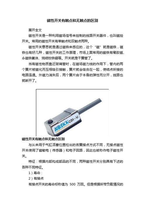
磁性开关有触点和无触点的区别展开全文磁性开关是一种利用磁场信号来控制的线路开关器件,也叫磁控开关。
常用的磁性开关有单触点和双触点两种。
磁性开关意思就是通过磁铁来感应的,这个“磁”就是磁铁,磁铁也有好几种,磁性开关的工作原理,市场上面常用的磁铁有橡胶磁、永磁铁氧体、烧结钕铁硼等。
开关就是干簧管了。
当有磁性物质靠近玻璃管时,在磁场磁力线的作用下,管内的两个簧片被磁化而互相吸引接触,簧片就会吸合在一起,使结点所接的电路连通。
外磁力消失后,两个簧片由于本身的弹性而分开,线路也就断开了。
磁性开关有触点和无触点区别与从来用于气缸活塞位置检出的舌簧接点方式不同,无接点磁性开关使用了磁敏电(传感器)和电子回路,因此也被称作电子磁性开关。
特征:根据内部构成部品的不同,两种磁性开关分别具有下述的各种不同特征。
1)寿命:2)有接点有接点开关的寿命标称值为500万回。
但是根据所带负载情况的不同,其寿命值也会有比较大的区别,一般分布在几百万回~1500万回之间。
b)无接点无接点开关的内部由于没有机械式的接点,因此寿命是半永久*的。
半永久:并不是指没有寿命的限制。
2)振荡现象:a)有接点舌簧接点在开闭时产生的弹动,会造成输出信号有振荡的现象。
b)无接点由于使用三极管进行ON/OFF动作,因此不会使输出信号产生振荡。
3)开闭容量:a)有接点由于对能流过舌簧接点的电流有限制,不能进行大容量的开闭。
b)无接点虽然基于三极管的热损失也有一定的限制,但是比有接点开关的上限容量大。
另外,对于瞬时间的变动(如突入电流等)有一定的余量保证空间。
4)内部电压降:有接点?无接点开关都要满足下述条件:电源(负载)电压-内部电压降>负载工作电压使用PLC时:ON电压)* 如果不能够满足上述条件时,负载不能正常ON(或一直保持OFF的状态)。
a)有接点因为显示灯(LED)串联在回路中,内部电压降也包括其顺方向的电压降。
实力值:2~3Vb)无接点二线式为使电子回路工作,不能将电压设置过低。
常用开关的种类及特点

常用开关的种类及特点电气装置中使用许多开关,开关的作用是断开、接通或转换电路,以控制电气装置的工作或停止。
它们的种类及规格非常多,应用十分广泛。
开关的文字符号用“S”或“xS”表示。
开关的“极”对应于过去所称的“刀”,“位”则对应于过去所称的“掷”,如:双极双位开关就是原称的双刀双掷开关。
开关的极相当于开关的活动触点(触头、触刀),位相当于开关的静止触点。
当技动或拨动开关时,活动触点就与静止触点接通(或断开),从而起到接通或断开电路的作用。
由于单极单位开关只有一个活动触点和一个静止触点,所以只能接通或断开一条电路。
单极双位开关则可选择接通(或断开)两条电路中的一条;双极双位开关可同时接通或断开两条独立的电路,其他极位开关的作用可依次类推。
1.滑动开关滑动开关的内部置有滑块,通过不同的方式驱动滑块,使滑块动作,开关触点接通或断开,从而起到开关作用。
滑动开关有拨动式、杠杆式、旋转式、推动式及软带式等。
(1)拨动式开关。
拨动式开关一般由金属外壳、塑料支架和开关片三部分组成,开关片的绝缘基体一般为玻璃丝板,上面压接有两排切入式固定触点;塑料支架上开有小槽,槽中相应固定咬合式滑动;金属外壳把塑料支架与开关片固定在一起。
当拨动开关时,塑料支架带动在开关片上的固定触片上滑动,定位珠和弹簧使开关动作定位淮确,并能保证在一定震动情况下不致错位常用的拨动式开关有1极2位、1极3位、2极2位、2极3位、4极3位、4极4位、10极3位、4极10位等。
其中大于3极的多极多位开关主要用做波段转换,有些波段开关的位数可多达十几位,可变换十几个挡位。
拨动式转换开关一般是直接焊在印制电路板上的,具有体积小、引线接线短、价格较低的优点,但由于结构上的原因,位数和刀数不可能做得太多,在电路中换接的电压不能太高,电流也不能太大。
拨动开关广泛应用于收音机、收录机、电视机及各种仪器仪表中,用做波段开关、声道转换开关、功能(收录放等)切换开关、磁带选择开关及杜比降噪开关等。
磁感应开关

磁感应开关磁感应开关也叫感应开关,是用来检测磁场的传感器。
在当今电气一体化的设备中,检测气缸活塞运动位置的传感器,磁感应开关无疑是首要选择。
磁感应开关可分为有触点式(机械式)和无触点式(电子式)两种。
一、有触点式磁感应开关有触点式磁感应开关是通过内部机械触点的接通与断开来工作的感应开关。
1、工作原理有触点式磁感应开关内部的主要元件是磁簧管(也叫舌簧管)如图5.4所示。
磁簧管的两块簧片是由软磁金属材料制成。
软磁材料在磁场环境中非常容易被磁化,而离开磁场环境后也非常容易消磁。
磁簧管图 5.4 磁感应开关内部原理图与接线图感应开关安装在带有磁环的气缸上,气缸活塞移动到一定位置,当活塞上的磁铁处在磁簧管正下方时,磁簧管内部的两块弹片分别被磁化成N极与S极,两块弹片因异性相吸而连接在一起,从而使开关导通,如图5.5(a)。
磁簧管图5.5(a)磁铁处于磁簧管正下方(b)磁铁处于磁簧管的某一侧当磁铁处在磁簧管的某一侧时,磁簧管的两块弹片会被磁化成相同的N极或S极,两块弹片因同性相弃而离得更远,如图5.5(b)。
见图5.6,活塞向右运动,当磁环到A位置时,磁簧管被接通,磁环移到B 位置时,磁簧管断开,A—B区间称为动作范围。
活塞向左反向运动,当磁环移到C位置,磁簧管才接通,当继续左行至位置D时,磁簧管才断开,C—D区间也是动作范围。
有触点磁性开关的动作范围一般在5~12mm,与开关型号及气缸缸径有关。
如图中A—D与C—B区间,只有活塞向某一个方向运动才可使开关接通的区间,称为磁滞区间,此区间通常小于2mm。
除去磁滞区间的动作范围为最适合安装位置,其中间位置称为最高灵敏度位置。
图5.6 磁感应开关动作区间图磁环停止在最高灵敏度位置,开关动作稳定,不易受外界干扰。
若磁环停止在磁滞区间,则开关动作不稳定,易受外界干扰。
2、特点磁簧管内部充入惰性气体,触点在开闭时可避免产生火花,同时可减少火花引起的氧化、碳化,触点镀贵金属、耐磨。
磁性开关说明

磁性开关的性能对比
磁性开关的选用
说明 序号 项目 有接点 1 无接点 2 3 用途 使用电压V 使用电压V 漏电流 无 3线式:100µA以下 线式:100 A 线式:1mA以下 2线式:1mA以下 动作时间ms 动作时间ms 1.2 ≤1 寿命 几千万次 半永久 适合高频工作 耐冲击性能m/s 耐冲击性能m/s2 300 500
磁性开关
本章要求掌握的主要内容: 本章要求掌握的主要内容:
1. 磁性开关的工作原理 2. 磁性开关的分类 3. 磁性开关的性能对比 4. 磁性开关的使用注意事项
磁性开关的工作原理
• 磁性开关是用来检测气缸活塞位置的: 磁性开关是用来检测气缸活塞位置的:即检测活塞的 运动行程的。它可分为有接点型和无接点型两种。 运动行程的。它可分为有接点型和无接点型两种。
磁性开关的使用注意事项
• 有接点磁性开关注意事项
ቤተ መጻሕፍቲ ባይዱ
1、安装时,不得让开关受过大的冲击力,如将开关打入、抛扔等, 、安装时,不得让开关受过大的冲击力,如将开关打入、抛扔等, 会损坏开关; 会损坏开关; 2、不能让磁性开关处于水或冷却液中使用; 、不能让磁性开关处于水或冷却液中使用; 3、绝对不要用于有爆炸性、可燃性气体的环境中; 、绝对不要用于有爆炸性、可燃性气体的环境中; 4、周围有强磁场、大电流(如电焊机等)的环境中应选用耐强磁场 、周围有强磁场、大电流(如电焊机等) 的磁性开关; 的磁性开关; 5、不要把连接导线和动力线(如电动机等)、高压线并在一起; 、不要把连接导线和动力线(如电动机等)、高压线并在一起; )、高压线并在一起
无接点电晶体型- 无接点电晶体型-抗强磁型
• 抗交流磁场型
CS1-69AM 磁感 应开关
只能用于直流电源,专用于 系列焊接夹紧缸; 只能用于直流电源,专用于MCK系列焊接夹紧缸; 系列焊接夹紧缸 目前我司暂未有抗直流强磁场型磁性开关。 目前我司暂未有抗直流强磁场型磁性开关。
艾礼富alef常用探测器种类及原理

艾礼富alef常用探测器种类及原理1.探测器的类型探测器类型一般有,红外、微波、震动、烟感、气感、玻璃破碎、压力、超声波等等。
其中红外探测器还可分为主动红外和被动红外,烟感还可分为离子式和光电式。
市面上常见的有红外探测器(被动红外)、对射、栅栏(主动红外)、双鉴探测器、震动探测器、玻璃破碎探测器。
2.开关式探测器开关式报警器开关式报警器是通过各种类型开关的闭合和断开来控制电路产生通、断,从而触发报警。
常见的开关有磁控开关、微动开关、压力垫,或用金属丝、金属条、金属箔等来代用的多种类型开关。
磁控开关又称磁控管或磁簧开关,由永久磁铁及干簧管组成。
磁控开关应该避免直接安装在金属物体上,必须使用时应使用钢门专用型磁控开关或改用微动开关或其它类型开关器件。
3.主动红外探测器主动红外探测器由红外发射器和红外接收器组成。
红外发射器发射一束或多束经过调制过的红外光线投向红外接收器。
发射器与接收器之间没有遮挡物时,探测器不会报警。
有物体遮挡时,接收器输出信号发生变化,探测器报警。
4.被动红外探测器被动红外探测器中有2个关键性元件,一个是菲涅尔透镜,另一个是热释电传感器。
自然界中任何高于绝对温度(-273o)的物体都会产生红外辐射,不同温度的物体释放的红外能量波长也不同。
人体有恒定的体温,与周围环境温度存在差别。
当人体移动时,这种差别的变化通过菲涅尔透镜被热释电传感器检测到,从而输出报警信号。
(菲涅尔透镜的作用:菲涅尔透镜有2个作用。
一个是将热释的红外辐射折射或反射到热释电传感器上,另一个作用是将探测区域分成若干个明区和暗区。
)5.双元四元红外探测器把2个性能相同,极性相反的热释电传感器整合在一起的探测器是双元探测器;把4个性能相同,极性相反的热释电传感器整合在一起的探测器就是四元探测器。
(温度补偿:在一般情况下,人的体温总是比环境温度高得多。
当入侵者运动时,传感器接收到红外的变化信号幅度较大而触发报警。
当附近环境温度升高到与人体温度接近时,入侵者在运动时传感器接收到的红外变化信号幅度就很小,这样有可能由于信号小于触发阀值而不会报警。