EN001说明书
卡西欧 E-XA 电子辞典 英文用户说明书
and then a
scroll key scrolls to the previous or next
screen.
Configuring Initial Settings
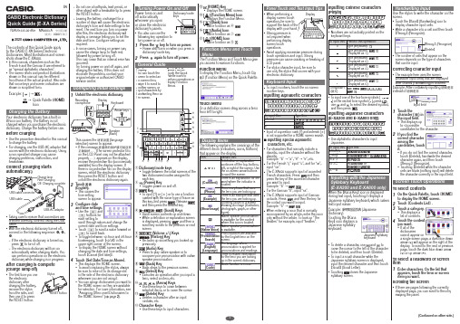
1 Unfold the electronic dictionary.
Recording microphone
Display Keyboard
Arrow keys
Speaker (back)
This causes the 语言设置 (language selection) screen to appear. • If the message 液晶屏的保护膜可能没有
– The electronic dictionary will turn on automatically when charging starts. You
can perform operations on the electronic
dictionary while charging is in progress.
• To display the HOME screen without
changing the date and time settings, touch【Cancel (Set later)】.
4 Touch【Set Date/Time as Above】.
• This displays the HOME screen. • To avoid misplacing the stylus, always
French è and the German ß are referred to as “special alphabetic characters”. • The screen shots and product illustrations shown in this manual may be different from those of the actual product. Also note that some keys and screen indicators are shown in simplified form.
UBS操作手册
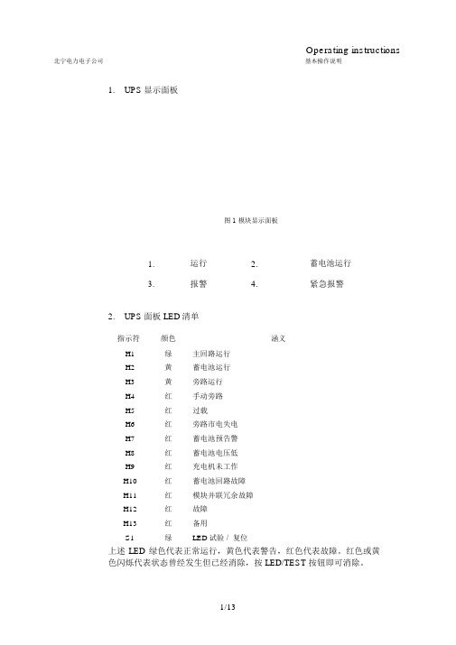
Operating instructions 北宁电力电子公司基本操作说明1.UPS显示面板图 1 模块显示面板1.运行2.蓄电池运行3.报警4.紧急报警2.UPS面板 LED清单指示符颜色涵义H1绿主回路运行H2黄蓄电池运行H3黄旁路运行H4红手动旁路H5红过载H6红旁路市电失电H7红蓄电池预告警H8红蓄电池电压低H9红充电机未工作H10红蓄电池回路故障H11红模块并联冗余故障H12红故障H13红备用S1绿LED试验 / 复位上述 LED 绿色代表正常运行,黄色代表警告,红色代表故障。
红色或黄色闪烁代表状态曾经发生但已经消除,按 LED/TEST 按钮即可消除。
北宁电力电子公司ENERTRONIC 系列模块化UPS 操作说明书3.UPS 模块的面板(3)输出功率(1) 开关 EIN/AUS(2) 模块状态旁路隔离熔断器发光二极管颜色涵义红故障绿输出有电压并连接负载LED 连续 :本模块的逆变器输出电压与系统的其他模块相同绿步,并联运行LED 闪烁 :逆变器是主模块绿输入电压在允许范围内绿逆变器电源开启北宁电力电子公司ENERTRONIC 系列模块化UPS 操作说明书1.UPS的菜单结构以下为第一级菜单,上为屏幕显示,下为中文翻译,分两段列出static conditionVoltage Current Power Main menuInverter Inverter P inverter Bypass mains Bypass mains S inverter Rectifier supply Rectifier supply P rectifier supplyMeasurement block voltage LNMeasurement block currentMeasurement block output active power<PW L1> A <Level 1> password is required for this menu<PW L2> A <Level 2> password is required for this menu<STPW Lx>Service Temporary Password <Level x> required switch to bypass<PW L1>switch to inverterswitch system on<PW L1>switch system off<PW L1>measurement valuesmodule settingssystem settingsclear all messages?service portalgeneral settingssystem logSafety-related operating steps also require a confirmation of the action, e.g."Switch to bypass" is followed by the message "Attempt to switch to bypass?"rollingCancel, BackOK, to sub-menugeneralsettingsdisplay time date clear hold module err PW L1PW L2<PW L1><PW L1><PW L2><STPW Lx><STPW Lx> languagehh:mm:ss tt.mm.jjjj delete to default to defaultengl./germancontrastbrightnessIncrease value (+)Decrease value (-)backlight Canceltimeout Next item, accept valuedisplayselftestpart no. DisplaySWpart no. DisplayHW北宁电力电子公司ENERTRONIC 系列模块化UPS 操作说明书静态条件下电压电流功率Main menu 逆变器逆变器逆变器有功功率切换至旁路<PW L1>旁路市电旁路市电逆变器视在功率切换到逆变器整流器市电整流器市电整流器功率启动系统<PW L1>关闭系统<PW L1>测量值火线和零线间的电压模块设置电流输出功率系统设置清除所有信息?<PW L1>第一级密码维护<PW L2>第二级密码一般设置<STPW Lx>需要临时密码系统日志和安全相关的操作需要确认如 "Switch to bypass"(切换至旁路)有"Attempt to switch to bypass?"(切换到旁路?)提示上下选择取消,后退OK ,到下级菜单北宁电力电子公司主菜单下“ Measurement value/ 测量值“的查看Operating instructionsENERTRONIC modular ENERTRONIC 系列模块化UPS 操作说明书load voltageUL1= (V)UL2= (V)UL3= (V)load currentIL1=...AIL2=...AIL3=...Ameasurement valuesload frequence load powerreal-powerf = ... Hzapparent-powerreactive-powercomplete system usv-module values battery-stringsrectifier ENERT.string 1HP 1(ok) B2loadmains......ENERT.string 3bypass HP 6 (err) m.b.loadmainsronly rec + bypew real-power apparent-power reactive-powerop poweronly rec.met voltage LN voltage LL current power frequence cos Phi sysbattery battery battery batt-chargerryet voltage current temperature charge remain time power tabbatteryinvertervoltagemains currentsystembypass temperaturebatterybattery chargelast cap-testbattery batteryremain timechargerdcdc lastcircuit cap-test北宁电力电子公司ENERTRONIC 系列模块化UPS 操作说明书2.报警和运行状态的图示和状态及故障指示灯表格运行值1234567 94整流器工作开95逆变器工作开92输出接触器闭合开96静态旁路工作开97蓄电池工作开98充电机工作开开99手动旁路闭合开北宁电力电子公司ENERTRONIC 系列模块化UPS 操作说明书1.单台 UPS的正常开机步骤步骤确认操作画√1确认 UPS主进线和旁路进线连接正确,2确认每个模块上的红色按钮在关状态,即按钮处于弹起的状态。
144LD_2MI_A_001_en

05.2003
MI EML0610 A-(en)
144LD Intelligent Buoyancy Transmitter with Torque Tube and Displacer for Level, Interface and Density with Communication HART / FoxCom
remote amplifier mounting kit
Repair and maintenance must be carried out by qualified personnel!
2
1 2 2.1 2.2 3 3.1 3.2 3.3 3.4 3.5 3.6 4 4.1 4.2 4.3 4.4 4.5 5 5.1 5.2 6 7 8 8.1 8.2 8.3 8.3.1 8.3.2 8.3.3 8.3.4 8.3.5 8.3.6 9 9.1
PAGE
DESIGN . . . . . . . . . . . . . . . . . . . . . . . . . . . . . . 3 MAINTENANCE, REPAIR . . . . . . . . . . . . . . . . 25 Visual inspectiont . . . . . . . . . . . . . . . . . . . . . . . 25 Sensor check. . . . . . . . . . . . . . . . . . . . . . . . . . 25 Amplifier check . . . . . . . . . . . . . . . . . . . . . . . . 25 Replacement of amplifier alectronics or sensor . 26 Replacing displacer . . . . . . . . . . . . . . . . . . . . . 28 Dismantling and Mounting of 10.6 10.8 10.10 10.12 10.14 11 12 13 14 14.1 14.2 14.2.1 14.2.2 14.2.3 14.2.4 14.2.5 Sensor section . . . . . . . . . . . . . . . . . . . . . . . 29 Connecting rod of sensor cell . . . . . . . . . . . . 31 Heat sink . . . . . . . . . . . . . . . . . . . . . . . . . . . 32 Torque tube . . . . . . . . . . . . . . . . . . . . . . . . . 32 Wafer body bearing . . . . . . . . . . . . . . . . . . . 33 DIMENSIONING OF DISPLACER. . . . . . . . . . 34 SAFETY REQUIREMENTS . . . . . . . . . . . . . . 36 DIMENSIONS . . . . . . . . . . . . . . . . . . . . . . . . . 37 SUPPLY OF TRANSMITTER . . . . . . . . . . . . . 38 General . . . . . . . . . . . . . . . . . . . . . . . . . . . . . . 38 Overview of application types . . . . . . . . . . . . . . 38 Supply via power supply unit . . . . . . . . . . . . . . 38 Direct supply . . . . . . . . . . . . . . . . . . . . . . . . . . 38 Communication . . . . . . . . . . . . . . . . . . . . . . . . 39 Operating via I/A-System . . . . . . . . . . . . . . . . . 39 Intrinsically-safe application . . . . . . . . . . . . . . . 39 10.1 10.2 10.3 10.4 10.5
AB品牌的S117-CA001A-EN-P安全开关产品说明书

DescriptionFeaturesSpecificationsSafety Ratings StandardsEN954-1, ISO13849-1, IEC/EN60204-1,NFPA79, EN1088, ISO14119,IEC/EN60947-5-1, ANSI B11.19,AS4024.1Safety ClassificationCat. 1 device per EN 954-1 dual channel interlocks suitable for Cat. 3 or 4systemsFunctional Safety Data (related to Safety Contacts) 1Note : For up-to-date information,visit /Safety/B10d: > 2 x 10⁶operations at min. load PFH D : < 3 x10⁻⁷MTTFd: > 385 yearsMay be suitable for use in performance levels Ple or Pld systems (according to ISO 13849-1:2006) and for use in SIL2or SIL3 systems (according to IEC 62061) depending on the architecture and application characteristics Certifications CE Marked for all applicable directives,cULus, TÜV , and CCCOutputsSafety Contacts (TLS-1 & -2) 3 N.C. direct opening action (TLS-3) 4 N.C. direct opening action Auxiliary Contacts (TLS-1 & -2) 2 N.O. (1 solenoid monitoring)(TLS-3 1 N.O.)Thermal Current I lth 10 A Rated Insulation Voltage (Ui) 500VSwitching Current @ Voltage, Min. 5 mA @ 5V DCUtilization Category A600/AC-15(Ue)600V 500V 240V 120V (le) 1.2 A 1.4 A3.0 A6.0 ADC-13(Ue)24V (le) 2 ASolenoid Characteristics Locking Type TLS-1 & -3 Power-to-Release TLS-2Power-to-Lock Holding Force, Max.2000 N (450 lbf)Releasable Load, Max.100 N (22.5 lbf)Power Supply 24V AC/DC or 110V AC or 230V AC (solenoid)Solenoid Power Typically 7 W 100% ED Escape Release Button Force max.: 50 N (11.25 lbs)Operating Characteristics Break Contact Force, Min.20 N (4.5 lbf)Actuation Speed, Max.160 mm (6.29 in.)/s Actuation Frequency, Max. 1 cycle/sOperating Radius, Min 160 mm (6.3 in.) [80 mm (3.15 in.) with flexible actuator]Operating Life @ 100 mA load 1,000,000 operations Environmental Enclosure Type Rating IP66, IP67 and IP69K Operating Temperature [C (F)]-20…+60° (-4…+140°)Physical Characteristics Housing Material UL Approved glass-filled PBT Actuator MaterialStainless Steel Weight [g (lb)]400 (0.88)ColorRed1Usable for ISO 13849-1:2006 and IEC 62061. Data is based on the B10dvalue given and:- Usage rate of 1op/10mins., 24hrs/day, 360 days/year, representing 51840 operations per year- Mission time/Proof test interval of 38 yearsThe safety contacts are described as normally closed (N.C.) i.e., with the guard closed, actuator in place (where relevant) and the machine able to be started.Power to release or power to lock High locking force ≤2000 N (450 lb)Five contacts: 2 N.C. & 1 N.O. for door position monitoring 1 N.C.& 1 N.O. or 2 N.C. for lock monitoring Rotatable head: 4 possible key entry slots Conforms to EN 1088 & EN 60947-5-1 Escape Release version availableIP69K, suitable for high pressure, high temperature washdownThe TLS-GD2 is a positive mode, tongue operated guard locking interlock switch that locks a machine guard closed until power is isolated and ensures that it remains isolated while the guard is open. It has three safety (N.C.) contacts and two auxiliary (N.O.)contacts. The TLS-GD2 head has two entry slots and it can be rotated to provide four actuator entry points. A blanking plug is provided to seat the unused slot.The guard may only be opened when a signal is applied to the TLS-GD2's internal solenoid which releases the lock mechanism. This signal can be via CU1 electronic timer relays or CU2 stopped motion detectors. Therefore the TLS-GD2 is ideal for machines which do not stop immediately or where premature interruption of the machine could cause damage to tooling and components or cause an additional hazard.The TLS-GD2 is available in three types. The TLS-1 GD2 and TLS-3GD2 incorporate a power-to-release function. Two manual release points with security screws allow the locked TLS-GD2 to bereleased in emergencies. An optional lid-mounted key-release style can also be supplied. The TLS-2 GD2 has a power-to-lock function.Each type of switch has five sets of contacts of various forms and are suitable for use with PLCs.The TLS-1 GD2 and TLS-3 GD2 are both available with escape release options. They are intended for machine guarding with full body access. The switch is installed so that the escape releasepush button on the rear side is accessible from inside the hazardous area. This allows the intentional unlocking of the TLS-GD2 from inside a hazardous area, providing a means of escape for a person who may become trapped.A stainless-steel actuator guide is fitted to protect the unit from actuator damage due to poor guard alignment or guard wear.TLS-GD2 has an ingress protection rating of IP69K making itsuitable for harsh washdown applications as found in the food and beverage, pharmaceutical, solar and semiconductor industries.Product Selection1Replace symbol with 2 (2 m), 5 (5 m), or 10 (10 m) for standard cable lengths.§For connector ratings, see page 3-9.♣With an 8-pin micro connector, not all contacts are connected. See page 3-45 for wiring details.Recommended Logic InterfacesConnection SystemsNote:For additional Safety Relays connectivity, see page 5-12.For additional Safety I/O and Safety PLC connectivity, see page 5-116.For application and wiring diagrams, see page 10-1.1Replace symbol with 2 (2 m), 5 (5 m), or 10 (10 m) for standard cable lengths.Replace symbol with 1 (1 m), 2 (2 m), 3 (3 m), 5 (5 m), or 10 (10 m) for standard cable lengths.‡Replace symbol with 0M3, (0.3 m), 0M6 (0.6 m), 1 (1 m), 2 (2 m) or 3 (3 m) for standard lengths.§The 9-wire cordset can be used only with the TLS3 versions.Note:For additional information, see page 7-1.Accessories5.5 (0.2TLS-GD2 Escape ReleaseIsometric ViewNote : 2D, 3D and electrical drawings are available on .Dimensions are shown in mm (in.). Dimensions are not intended to be used for installation purposes.Approximate DimensionsTypical Wiring Diagrams1Replace symbol with 2 (2 m), 5 (5 m) or 10 (10 m) for standard cable lengths. See WARNING notes on page 3-41.。
LSCg001e_neo_REV_15_Serie_ZH说明书

使用说明目录1.概述 (4)1.1.版权 (4)1.2.安全信息符号 (4)1.3.免责声明 (4)1.4.制造商、适用标准和CE认证 (4)1.5.向制造商和监管机构报告 (7)1.6.用户安全操作说明和用户资质要求 (7)2.产品使用寿命和保修条件 (7)3.交付范围 (8)4.预期用途 (9)4.1.器械的用途 (9)5.设置和调试。
(9)6.电气连接 (10)7.产品描述和控制 (11)7.1.连接 (11)7.1.1.电源连接 (11)7.1.2.开/关和启动开关 (11)7.1.3.电源插座 (12)7.2.头枕和操纵杆盒上的控制装置 (13)7.2.1.取下头枕泡沫垫 (14)7.3.EAZY GO轮(可选件) (14)7.4.更换保险丝 (15)7.5.P ATIENT S UPPORT S YSTEM LSC NEO 上的安全信息和信息标签 (16)8.PATIENT SUPPORT SYSTEM LSCNEO 操作 (21)8.1.设置和(重新)定位P ATIENT S UPPORT S YSTEM LSC NEO (21)8.2.开关开启和参考程序。
(21)8.3.旋转顶部 (22)8.3.1.Patient Support System LSCneo使用激光装置操作。
(23)8.4.调整头枕 (23)8.4.1.电动高度调整 (23)8.4.2.机械头枕腹侧/背侧倾斜 (23)8.4.3.紧急程序、电源故障或其他技术故障。
(24)8.5.操纵杆 (24)8.5.1.操纵杆和电动头枕控制装置可用性 (24)8.5.2.操作模拟操纵杆 (24)8.5.3.控制 Z、Y 和 X 轴 (25)8.5.4.自动运动 (25)8.5.5.反向功能 INV (25)8.6.紧急停止按钮和重启程序。
(26)9.清洁洁洁洁洁护 (27)10.维护 (27)11.产品安全检查 (27)12.器械废弃处置 (27)13.技术数据 (28)14.故障排除 (30)15.电磁兼容性(EMC) (31)15.1.电源电缆简介 (36)1. 概述为了安全操作和控制 Patient Support System LSCneo ,请仔细阅读本用户手册。
EN-SW10m-001 PoE 网络交换机用户手册说明书

Contents1 Introduction (3)2 Hardware Description (3)2.1 Front Panel (3)2.2 LED Indicators (3)2.3 Rear Panel (4)2.4 Specification (4)3 Getting Started (5)3.1 Management Options (5)3.2 Using Web-based Management (5)4.Configuration (6)4.1 Welcome (6)4.2 Administrator (7)4.3 Port Management (11)4.4 VLAN Setting (13)4.5 Per Port Counter (15)Per Port Counter -> Port Counter (15)4.6 QoS Setting (16)4.7 Security (17)4.8 Spanning Tree (19)4.9 DHCP Relay Agent (20)4.10 Backup/Recovery (22)4.11 Miscellaneous (22)4.12 SNMP Settings (23)4.13 Logout (23)4.14 PoE Settings (24)1 IntroductionPower-over-Ethernet (PoE) eliminates the need to run DC power to other devices on a wired LAN. Using a Power-over-Ethernet system, installers need to run only a single Category 5 Ethernet cable that carries both power and data to each device. This allows greater flexibility in the locating of network devices and, in many cases, significantly decreases installation costs.There are two system components in PoE - the PSE (Power Sourcing Equipment) and the PD (Powered Device). The IEEE 802.3af/at specification defines PSE as a device that inserts power onto an Ethernet cable. The PSE may be located at the switch (End-span configuration). or it may be a separate device located between the switch and the PD (Mid-span configuration). The PD is the natural termination of this link, receiving the power, and could be an IP phone, a WLAN access point, or any other IP device that requires power. The current is transmitted over two of the four twisted pairs of wires in a Category-5 cable.Power-over-Ethernet follows the IEEE 802.3af/at specification and is completely compatible with existing Ethernet switches and networked devices. Because the Power Sourcing Equipment (PSE) tests whether a networked device is PoE-capable, power is never transmitted unless a Powered Device is at the other end of the cable. It also continues to monitor the channel. If the Powered Device does not draw a minimum current, because it has been unplugged or physically turned off, the PSE shuts down the power to that port. Optionally, the standard permits Powered Devices to signal t0 the PSEs exactly how much power they need.The PoE switch is a multi-port fast Ethernet switch that can be used to build high-performance switched workgroup networks. This switch is a store-and-forward device that offers low latency for high-speed networking. It also features a ‘store-and-forward switching’ scheme that allows the swi tch to auto-learn and store source addresses in a 8K-entry MAC address table. The switch is targeted at workgroup, department or backbone computing environments.2 Hardware Description2.1 Front PanelThe front panel consists of LED indications, reset button and 8x10/100 PoE ports + TX+1 GigabitCombo+1Gigabit SFP with 8 PoE Ethernet Switch2.2 LED IndicatorsPower LED: The Power LED lights up when the switch is connected to a power source.Link/Act LED:Green (for megabit ports): Indicates that the port is running at 100M.Green (for gigabit ports): Indicates that the port is running at 100M.Blinking: Indicates that the switch is either sending or receiving data to the port.Light off: No link.PoE LED:Green: Indicates the PoE powered device (PD) is connected and the port supplies power successfully.Light off: Indicates no powered device (PD) connected.Reset: By pressing the Reset button for 5 seconds the switch will change back to the default configuration and all changes will be lost.2.3 Rear PanelThe rear panel view of the switch consists of Reset button and DC input plug.2.4 Specification3 Getting StartedThis chapter introduces the management interface of the switch.3.1 Management OptionsThe Switch can be managed through any port on the device by using the Web-based ManagementEach switch must be assigned its own IP Address, which is used for communication with Web-Based Management. The PC’s IP address should be in the same range as the switch. Each switch ca n allow only one user to access the Web-Based Management at a time.Please refer to the following installation instructions for the Web-based Management.3.2 Using Web-based ManagementAfter a successful physical installation, you can configure the switch, monitor the network status, and display statistics using a web browser.Connecting to the SwitchYou will need the following equipment to begin the web configuration of your device:⏹ A PC with a RJ-45 Ethernet connection⏹ A standard Ethernet cableConnect the Ethernet cable to any of the ports on the front panel of the switch and to the Ethernet port on the PC. Login Web-based ManagementIf DHCP is not enabled on the local LAN, the switch will be able to log in to the web page with 192.168.2.1 after 2 minutes. If DHCP is enabled, the DHCP server (router) will assign the address to the switch, and use DHCP to log in to the switch. Login to the switch web page.In case no DHCP server, In order to login and configure the switch via an Ethernet connection, the PC must have an IP address in the same subnet as the switch. For example, if the switch has an IP address of 192.168.2.1, the PC should have an IP address of 192.168.2.x(where x is a number between 2 ~ 254), and a subnet mask of 255.255.255.0. Open the web browser and enter 192.168.2.1 (the factory-default IP address) in the address bar. Then press <Enter>.When the following logon dialog box appears, enter the username and password then click OK. The default username is admin and password is system.Note: If the DHCP server (routing) to the switch assigned address, you can use the Auto Discovery tool to query the switch ip4.ConfigurationThe features and functions of the switch can be configured for optimum use through the Web-based Management.4.1 WelcomeAfter a successful login you will see the screen bellows:4.2 AdministratorAdministrator -> Authentication ConfigurationHere you can enter a new Username/Password and confirm it.The factory defaultIP address: 192.168.2.1Username: adminPassword: systemAdministrator -> System IP ConfigurationThere are two ways for the switch to obtain an IP address: Static and DHCP (Dynamic Host Configuration Protocol).If the switch is used to open the DHCP environment, the switch will automatically obtain an IP address from a DHCP server, the switch for the landing web page, As shown below:When using static mode, the IP address, Subnet Mask and Gateway can be manually configured. When using DHCP mode, the Switch will first look for a DHCP server to provide it with an IP address (including network mask and default gateway) before using the default or previously entered settings. By default the IP setting is static mode with IP address is 192.168.2.1 and subnet mask is 255.255.255.0Administrator -> System StatusComment: By entering a Comment, the device can more easily be recognized on the LAN.Idle Time Security: It controls the idle time-out period for security purposes, when there is no action for a specific time span in the Web-based Management. If the current session times out (expires), the user is required a re-login before using the Web-based Management again. Selective range is from 3 to 30 minute, and the defaultsetting is 5 minutes.Administrator -> Load default settingProvide a safe reset option for the switch. All configuration settings in non-volatile RAM will be reset to factorydefault and then the switch will reboot.Administrator -> Firmware UpdateYou must enter the password of device in order to determine the firmware needs to be updated.After a correct password the switch will erase the old firmware first.After completing the erase you will see the screen bellows. Specify the Firmware Path (or Browse for one) that you are going to use, and then click Update. The state will show ‘OK’ after completion and ‘Fail’ is firmware upgrade fails or cannot be completed for any reason.Administrator -> Reboot DeviceProvide a safe way to reboot the system. Click Reboot to restart the switch.4.3 Port ManagementPort Management -> Port ConfigurationIn this page, the status of all ports can be monitored and adjusted for optimum configuration.Enable: Enable or disable the port’s connectionAuto-Nege: Enable or disable port auto-NDI/MDIXSpeed: Copper connections can operate in Forced Mode settings (1000M Full, 100M Full, 100M Halt, 10M Full,10M Half), Auto, or Disabled. The default setting for all ports is Auto.Duplex: Copper connections can operate in Full-Duplex or Half-Duplex ModeAddr. Learning: Enable or disable port learning MAC address.Port Management -> Port MirroringPort Mirroring is a method of monitoring network traffic that forwards a copy of each incoming and/or outgoing packet from one port of the Switch to another port where the packet can be studied. This enables network managers to better monitor network performances.TX (transmit) mode: Duplicates the data transmitted from the source port and forwards it to the Target Port. Click “all” to include all ports into port mirroring.RX (receive) mode: Duplicates the data that received from the source port and forwards it to the Target Port. Click “all” to include all ports into port mirroring.Both (transmit and receive) mode: Duplicate both the data transmitted from and data sent to the source port, and forwards all the dat a to the assigned Target Port. Click “all” to include all ports into port mirroring.The target ports will stop mirroring packets if there are unknown tags or destination packets sent out by source ports.Port Management -> Bandwidth ControlThe Band width Control page allows network managers to define the bandwidth settings for a specified port’s transmitting and receiving data rates.TX Rate: This allows you to enter data receive rate from 0 to 255 (base on speed base), 0 for full speed.RX Rate: This allows you to enter data transmit rate from 0 to 255 (base on speed base), 0 for full speed. Speed Base:Port Management -> Broadcast Storm ControlThe Broadcast Storm Control feature provides the ability to control the receive rate of broadcast packets. Once a packet storm has been detected, the Switch will drop packets coming into the Switch until the stormhas subsided.4.4 VLAN SettingVLAN Setting -> VLAN ModeA VLAN is a group of ports that can be anywhere in the network, but communicate as though they were in thesame area. VLANs can be easily organized to reflect department groups (such as R&D, Marketing), usagegroups (such as e-mail), or multicast groups (multimedia applications such as video conferencing), andtherefore help to simplify network management by allowing users to move devices to a new VLAN without having to change any physical connections.Prot Based VLAN: Port-Based VLANs are the simplest and most common form of VLAN. It assigns the appliance LAN ports to VLANs, effectively transforming the appliances. You can assign multiple ports to the same VLAN, or each port to a separate VLAN.802.1Q VLAN: By default, 802.1Q VLAN is disabled. With 802.1Q VLAN enabled, the VLAN VID 1 is created by default with an empty VLAN name field and all ports are configur ed as “Untagged” members.VLAN SettingAdd VLAN: Click to create a new VLAN name and to select VLAN ports. The VLAN name should be less than 10 characters. To save the members in a group, click Add.VLAN Setting ->VLAN Setting ->4.5 Per Port CounterPer Port Counter -> Port CounterThe Statistics screen displays the status of each port packet count.QoS Setting -> Priority ModeQoS Setting -> Port, 802.1p ,IP/DS basedQoS Setting -> TCP/UDP Port BasedSecurity -> MAC Address BindingSecurity -> Scan MACSecurity -> TCP/UDP FilterSecurity -> Web Management Filter 4.8 Spanning TreeSpanning Tree -> STP Bridge SettingsSpanning Tree -> STP Port SettingsSpanning Tree -> Loopback DetectionDHCP Relay Agent -> DHCP Relay AgentDHCP Relay Agent -> Relay ServerDHCP Relay Agent -> VLAN MAP Relay Agent4.10 Backup/RecoveryAllow the current configuration settings to be saved to a file (not including the password), and if necessary, you can restore configuration settings from the file.Backup or restore the configuration file to or from your local drive.Click Download to save the current settings to your disk.Click Browse to browse your inventories for a saved backup settings file.Click Update after selecting the backup settings file you want to restore.Switch will reboot after restore and all current configurations will be lost4.11 MiscellaneousMiscellaneous -> Miscellaneous Settings4.12 SNMP Settings4.13 LogoutClick this to end this sessionIf you close the web browser without clicking the Logout button, it will be seen as an abnormal exit and the login session will still be occupied.4.14 PoEPoE -> PoE SettingThis section provides PoE (Power over Ethernet) Configuration and PoE output status of PoE Switch.Main Power consumption:The Statistics screen displays the total Watts usage of PoE Switch.Status: Can enable or disable the PoE function.Class: Class 0 is the default for PDs. However, to improve power management at the PSE, the PD may opt to provide a signature for Class 1 to 4.The PD is classified based on power. The classification of the PD is the maximum power that the PD will draw across all input voltages and operational modes. A PD shall return Class 0 to 4 in accordance with theCurrent (mA): It shows the PoE device current Amp.Current-Limit (mA): It can limit the port PoE supply Amp. Per port maximum value must less 600. Once power overload detected, the port will auto shut down and we should manually enablethe PoE port.PoE -> PoE Power DelayThis section provides PoE Power Delay Configuration.Delay Mode: Enable or disable the port’s PoE Power Delay function.Delay Time: Set PoE power delay time (0~300).PoE -> PoE SchedulingPoE Schedule user can configure a duration time for PoE port as default value does not provide power.: Please enable NTP and correct the System Time first.As default value, all PoE Schedule Profile functions are disabledPlease use mouse to click on the block about what time you want to supply power for PoE port. PoE -> NTP SettingThis section provide the NTP Configuration of PoE SwitchSystem Time: Display current time informationNTP Server: Allow assign #1 or #2 NTP server IP address manuallyTime Zone: Allow select the time zone according to current locationPoE -> PoE Auto-checkThe PoE Switch can be configured to monitor connected PD’s status in real-time via ping action. Once the PD stops working and without response, the PoE Switch is going to restart PoE port power, and bring the PD back to work. It will greatly enhance the reliability and reduces administrator management burden.If you do not fill inautoping address, will have the following tips.If the address is not filled, there will be web tipsSet Port No.: Select the port wich you want to set IP AddressIP Address: Allow assign IP address which you want to monitorChecking Time: Select checking time ping action (1-10Min)Reset Delay Time: Select PD Reset time (1-3Seconds)Enable Checking Port. No: Select the port which you want to enable PoE Auto-check------------------------The end------------------------------------。
时代电子产品TD012030EN产品说明书

ContentsDescriptionPageCatalog Number Selection . . . . . . . . . . . . . . . . . . . . . . . . . . . . . . . . . . . . . . . . . . . . . . . . . . . . . . . . . . . . . . . . . . . . .3Digitrip 310+ Electronic T rip Unit types RGH, RGCLong Delay Response and Short Delay with Flat Response and Override(LSI, LSIG, ALSI, ALSIG) . . . . . . . . . . . . . . . . . . . . . . . . . . . . . . . . . . . . . . . . . . . . . . . . .TC01210020E . . . . . . . .5Long Delay Response and Short Delay with I 2T Response Curve and Override (LS, LSG) TC01210021E . . . . . . . .6Ground Fault Delay Response Curve (LSG, LSIG, ALSIG) . . . . . . . . . . . . . . . . . . . . . . . . .TC01210022E . . . . . . . .7Maintentance Mode / Instantaneous Setting 1600A / 2000A (ALSI, ALSIG) . . . . . . . . . . .TC01210024E . . . . . . . .8Maintentance Mode / Instantaneous Setting 2500A (ALSI, ALSIG) . . . . . . . . . . . . . . . . .TC01210023E . . . . . . . .9Digitrip RMS 310 Electronic T rip Unit typesTypical Instantaneous Time-Phase Current Characteristic Curve Based on I n . . . . . . . . . . .SC-5629-93 . . . . . . . .10Typical Long Delay/Short Delay Time-Phase Current Characteristic Curve Based on I n . . .SC-5630-93 . . . . . . . .11Typical Ground Fault/Protection Time/Current Characteristic Curve Based on I n . . . . . . . . .SC-5631-93 . . . . . . . .12Note:The following curves meet the requirements of UL, CSA, IEC, CCC and CE .The following circuit breakers are derived from Eaton, Westinghouse, or Cutler-Hammer history .Time Current Curves are engineering reference document for application and coordination purposes only .Series G R-Frame800-2500A, 240-690Votee:NUnless noted below, all curves remain unchanged from their prior revision .2Time Current Curves TD012030ENEffective September 2015Series G R-FrameEATON 3Time Current Curves TD012030ENEffective September 2015Series G R-Frame EATON RG H 3 250 39 ZG E CFrameRGAmperes160 = 1600200250= 2000= 2500RatingBlank = 80% rated C = 100% rated (except 2500A)FeatureTerminationsM = Metric tapped line/load conductorsE = Imperial tapped line/load conductorsTrip Unit33323535B223636B22383939B22 = 310+ Electronic LS = 310+ Electronic LSI = 310+ Electronic LSG= 310+ Electronic LS(A), GFA, no trip = 310+ Electronic LSIG= 310+ Electronic LSI(A), GFA, no trip = 310+ Electronic ALSI with Maintenance Mode = 310+ Electronic ALSIGwith Maintenance Mode = 310+ Electronic ALSI(A)with Maintenance Mode and GFA, no tripPoles3 = Three 4= FourBlank B20B21ZG = No feature = High load alarm = Ground fault= Zone selective interlockingPerformance600480415240H C50657012565100100200T able 1. RG Circuit Breaker/FrameCatalog Number SelectionThis information is presented only as an aid to understanding catalog numbers .It is not to be used to build catalog numbers for circuit breakers or trip units .4Time Current Curves TD012030ENEffective September 2015Series G R-Frame EATON Figure 1. Digitrip 310+ Faceplates5Time Current Curves TD012030ENEffective September 2015Series G R-FrameEATON Figure 2. Digitrip 310+ Long Delay Response and Short Delay with Flat Response and Override Curve (LSI, LSIG, ALSI, ALSIG) - Curve Number TC01210020E, September 20176Time Current Curves TD012030ENEffective September 2015Series GR-FrameEATON Figure 3. Digitrip 310+ Long Delay Response and Short delay with I 2T Response Curve (LS, LSG) - Curve Number TC01210021E,September 20177Time Current Curves TD012030ENEffective September 2015Series G R-FrameEATON Figure 4. Ground Fault Delay Response Curve (LSG, LSIG, ALSIG) Curve Number TC01210022E, June 2012Time Current Curves TD012030EN Effective September 2015Series G R-FrameEATON Figure 5. Maintenance Mode/Instantaneous Setting 1600A/2000A (ALSI, ALSIG) - Curve Number TC01210024E, September 201589Time Current Curves TD012030ENEffective September 2015Series G R-FrameEATON Time Current Curves TD012030EN Effective September 2015Series G R-Frame10EATON nAB DE-ION Circuit Breakers11EATON Figure 8. T ypical Long Delay/Short Delay Time-Phase Current Characteristic Curve Based on I n - Curve Number SC-5630-93, October 1997AB DE-ION Circuit BreakersT ypes RD, CRD, RDC, CRDC Equipped With Digitrip RMS 310 T rip UnitsT ypical Long Delay/Short Delay Time-Phase Current Characteristic Curve Based on I12EATON n AB DE-ION Circuit BreakersT ypes RD, CRD, RDC, CRDC Equipped With Digitrip RMS 310 T rip UnitsT ypical Ground Fault/Protection Time/Current Characteristic Curve Based on I n13 EATON 14EATON 15 EATON Eaton1000 Eaton Boulevard Cleveland, OH 44122 United StatesEaton .com© 2017 EatonAll Rights ReservedPrinted in USAPublication No . TD012030EN / TBG 001369 September 2017Eaton is a registered trademark . All other trademarks are property of their respective owners .。
迪伦克(Endress+Hauser)流动度量器系列用户操作手册说明书

Products Solutions Services SD00188F/00/EN/13.1371238762Functional safety manualLiquiphant M/S with FEL56and Nivotester FTL325NLevel Limit Measuring SystemApplicationMinimum detection (also dry running protection) of all types of liquids in tanks to satisfy particular safety systems requirements as per IEC 61508/IEC 61511-1.The measuring device fulfils the requirements concerning •Safety functions up to SIL 2•Explosion protection by intrinsic safety or flameproof enclosure•EMC to EN 61326 and NAMUR RecommendationNE 21.Your benefits•For minimum detection up to SIL 2–Independently assessed (Functional Assessment) by as per IEC 61508/IEC 61511-1•Monitoring for corrosion on the tuning fork of the sensor•No calibration•Fault message for circuit break and short-circuit •Functional test of subsequent devices at the pushof a button•Protected against outside vibration•Easy commissioningLiquiphant M/S with FEL56 and Nivotester FTL325N2Endress+HauserTable of contentsSIL declaration of conformity . . . . . . . . . . . . . . . . . . . . .3Introduction. . . . . . . . . . . . . . . . . . . . . . . . . . . . . . . . . . . .4General depiction of a safety system (protection function) . . . 4Structure of the measuring system . . . . . . . . . . . . . . . .5Level limit measuring system . . . . . . . . . . . . . . . . . . . . . . . . . . . . 5Safety function . . . . . . . . . . . . . . . . . . . . . . . . . . . . . . . . . . . . . . . . 5Permitted device types . . . . . . . . . . . . . . . . . . . . . . . . . . . . . . . . . 6Safety function data . . . . . . . . . . . . . . . . . . . . . . . . . . . . . . . . . . . 7Supplementary device documentation . . . . . . . . . . . . . . . . . . . . 7Settings and installation instructions . . . . . . . . . . . . . .9Installation instructions . . . . . . . . . . . . . . . . . . . . . . . . . . . . . . . . 9Response in operation and failure . . . . . . . . . . . . . . . 10Recurrent function tests of the measuring system . 10Appendix . . . . . . . . . . . . . . . . . . . . . . . . . . . . . . . . . . . . 11Specific values and wiring options for themeasuring system . . . . . . . . . . . . . . . . . . . . . . . . . . . . . . . . . . . . 11Exida Management Summary. . . . . . . . . . . . . . . . . . . 18Supplementary Documentation . . . . . . . . . . . . . . . . . . . . . . . . . 20Liquiphant M/S with FEL56 and Nivotester FTL325NEndress+Hauser 3SIL declaration of conformitySIL-04001B-00-A2Liquiphant M/S with FEL56 and Nivotester FTL325N4Endress+HauserIntroductionGeneral depiction of a safety system(protection function)Parameter tables for determining Safety Integrity Level (SIL)The following tables are used to define the reachable SIL or the requirements pertaining to the“Average Probability of Dangerous Failure on Demand” (PFD av ), the “Hardware Fault Tolerance” (HFT)and the “Safe Failure Fraction” (SFF) of the safety system. The specific values for the Liquiphant M/S +Nivotester FTL325N measuring system can be found in the Appendix.Permitted probabilities of dangerous failures on demand of the complete safety related systemdependent on the SIL (e.g. exceeding a defined MIN level/switch point) (Source: IEC 61508, Part 1):The following table shows the achievable Safety Integrity Level (SIL) as a function of the probability fraction of safety-oriented failures and the "hardware fault tolerance" of the complete safety system for type B systems (complex components, not all faults are known or can be described).For general informationen about SIL please refer to: /silSIL PFD av4≥ 10-5 to < 10-43≥ 10-4 to < 10-32≥ 10-3 to < 10-21≥ 10-2 to < 10-1SFFHFT 01 (0)1)1)In accordance with IEC 61511-1 (FDIS) (chapter 11.4.4), the HFT can be reduced by one (values in brackets) if the devices used fulfil the following conditions:- The device is proven in use,- Only process-relevant parameters can be changed at the device (e.g. measuring range, ...),- Changing the process-relevant parameters is protected (e.g. password, jumper, ...),- The safety function requires less than SIL 4.All conditions apply to Liquiphant M/S + Nivotester FTL325N.2 (1)1< 60%not allowed SIL 1SIL 260% to < 90%SIL 1SIL 2SIL 390% to < 99%SIL 2SIL 3≥ 99%SIL 3Liquiphant M/S with FEL56 and Nivotester FTL325NEndress+Hauser 5Structure of the measuring systemLevel limit measuring systemThe measuring system's devices are displayed in the following diagram (example).1FEL - Electronic insert A Nivotester FTL325N (one-channel)2Liquiphant M/S B Nivotester FTL325N (three-channel)Safety functionThe safety function applies to all settings in MIN safety (monitoring of the covered state) and use of the NO contacts of the level relays.The following settings are permitted for the safety function:The level relay always works in quiescent current safety; i.e. the relay releases when:•The switch point is undershot (level falls below response height)•A detected fault occurs •The mains voltage failsIn addition to the level relay, the alarm relay works in quiescent current safety and releases when:•One of the following faults occurs: –the sensor connection is interrupted –the sensor connection short circuits •The mains voltage failsDevice SettingAs-delivered state Liquiphant•Density switch setting: 0,5•Density switch setting: 0,7Density switch setting: 0,7"MIN" safety"MAX" safetyNivotesterFTL325N-#3#3Error current signal > 2,1 mAError current signal > 2,1 mA All settings except" S function" (see section "Settings and instal-lation instructions")Three-channel operationThe DIL switch for fault messaging(short-circuit-, and circuit break-monitoring)must be set to the ON position.Failure switch "ON"NivotesterFTL325N-#1#1Error current signal > 2,1 mAError current signal > 2,1 mA One-channel operationThe DIL switch for fault messaging(short-circuit-, and circuit break-monitoring)must be set to the ON position.Failure switch "ON"When the alarm relay releases, the level relay also releases.Liquiphant M/S with FEL56 and Nivotester FTL325N6Endress+HauserPermitted device typesThe details pertaining to functional safety in this manual relate to the device versions listed below and are valid as of the specified firmware and hardware version.Unless otherwise specified, all subsequent versions can also be used for safety instrumented systems.A modification process according to IEC 61508 is applied for device changes.Valid device versions for safety-related use:Valid firmware version: as of 01.00.00Valid hardware version (electronics): as of 01.00Valid device versions for safety-related use:Valid firmware version: as of 01.00.00Valid hardware version (electronics): as of 01.00Valid device versions for safety-related use:Liquiphant M FTL50, FTL50H, FTL51, FTL51C, FTL51H+ FEL56Feature Designation Option model 010Approvalall 020Process connection all 030Probe length; Type all 040Electronics; Output 6FEL56; SIL NAMUR (L-H signal)050Housing; Cable Entry all 060Additional optionsallLiquiphant S FTL70, FTL71+ FEL56Feature Designation Option model 010Approvalall 020Process connection all 030Probe length all 040Electronics; Output 6FEL56; SIL NAMUR (L-H signal)050Housing; Cable entry all 060Additional option all 070ApplicationallNivotester FTL325N Feature Designation Option model 010ApprovalG H N P T WATEX II 3(1)G Ex nC/A (ia) IIC T4, SIL, IECEx Zone 2ATEX II (1)GD (Ex ia) IIC, WHG, SIL, IECEx (Ex ia) IIC (Liquiphant M / Liquiphant S)NEPSI (Ex ia) IIC, SIL (Liquiphant M / Liquiphant S)FM IS Cl. I, II, III Div. 1 Gr. A-G, SIL (Liquiphant M / Liquiphant S)CSA IS Cl. I, II, III Div. 1 Gr. A-G, SIL (Liquiphant M / Liquiphant S)TIIS Ex ia IIC, SIL, labeling in Japan020Housing all 030Power Supply all 040Switch outputallLiquiphant M/S with FEL56 and Nivotester FTL325NEndress+Hauser 7Safety function data•The mandatory settings and data for the safety function can be found in chapter "Safety function", →ä5 and chapter "Settings and installation instructions", →ä9.•The measuring system reacts in ≤ 1,4 s.Supplementarydevice documentationMTTR is set at eight hours.Safety systems without a self-locking function must be monitored or set to an otherwise safe state after carrying out the safety function within MTTR.Liquiphant M FTL50, FTL50H, FTL51, FTL51H, FTL51C DocumentationContents CommentTechnical Information•FTL50, FTL50H, FTL51, FTL51H:TI00328F/00/EN •FTL51C:TI00347F/00/EN –Technical data –Accessories–The documentation is available on the Internet:→ .Operating Instructions •FTL50, FTL51:KA00143F/00/A6KA00163F/00/A61)•FTL50H, FTL51H:KA00144F/00/A6KA00164F/00/A61)•FTL51C:KA00162F/00/A6KA00165F/00/A61)1)with aluminium housing / separate terminal compartment.–Installation –Wiring –Operation–Commissioning –Troubleshooting –Repair–Maintenance–The documentation is supplied with the device.–The documentation is also available on the Internet:→ .Safety instructions depending on the selected version"Approval"Safety, installation andoperating instructions for devices, which are suitable for use in potentially explosive atmospheres or as overfillprotection (WHG, German Water Resources Act).Additional safety instructions (XA, ZE) are supplied with certified device versions. Please refer to the nameplate for the rele-vant safety instructions.Liquiphant S FTL70, FTL71Documentation Contents CommentTechnical Information TI00354F/00/EN –Technical data –Accessories –The documentation is available on the Internet:→ .Operating Instructions KA00172F/00/A6KA00173F/00/A61)1)with aluminium housing / separate terminal compartment–Installation –Wiring –Operation–Commissioning –Troubleshooting –Repair–Maintenance–The documentation is supplied with the device.–The documentation is also available on the Internet:→ .Safety instructions depending on the selected version"Approval"Safety, installation andoperating instructions for devices, which are suitable for use in potentially explosive atmospheres or as overfillprotection (WHG, German Water Resources Act).Additional safety instructions (XA, ZE) are supplied with certified device versions. Please refer to the nameplate for the rele-vant safety instructions.Liquiphant M/S with FEL56 and Nivotester FTL325N8Endress+HauserNivotester FTL325N Documentation Contents CommentTechnical Information TI00353F/00/EN –Technical data –Accessories –The documentation is available on the Internet:→ .Operating Instructions •One-channel device:KA00170F/00/A6 •Three-channel device:KA00171F/00/A6–Installation –Wiring –Operation–Commissioning –Troubleshooting –Repair–Maintenance–The documentation is supplied with the device.–The documentation is also available on the Internet:→ .Safety instructions depending on the selected version"Approval"Safety, installation andoperating instructions for devices, which are suitable for use in potentially explosive atmospheres or as overfillprotection (WHG, German Water Resources Act).Additional safety instructions (XA, ZE) are supplied with certified device versions. Please refer to the nameplate for the rele-vant safety instructions.Liquiphant M/S with FEL56 and Nivotester FTL325NEndress+Hauser 9Settings and installation instructionsInstallation instructionsPlease refer to the Compact Instructions (KA) for information regarding the correct installation of Liquiphant M/S + Nivotester FTL325N.Since the application conditions have an effect on the safety of the measurement, pay attention to the notes in the Technical Information (TI) and Compact Instructions (KA).The ambient conditions for the Nivotester FTL325N must correspond to IP54 (in accordance with EN 60529).The manuals on setting the devices can be found in the section "Supplementary device documentation", →ä7.Settings for Liquiphant M/S (FEL56):•The density switch setting must be configured according to the density range of the medium.•The settings of the safety mode has an effect on the function. The DIL switch must be set to MIN for minimum detection in a SIL application.Settings for Nivotester FTL325N-#3#3 (three-channel version):Observe the following for the Nivotester FTL325N-####: The operator must use suitablemeasures (e.g. current limiter, fuse) to ensure the relay contact characteristics are not exceeded:•U ≤ 253 V AC 50/60 Hz , I ≤ 2 A, P ≤ 500 VA at cos ϕ ≥ 0,7 or •U ≤ 40 V DC, I ≤ 2 A, P ≤ 80 WChanges to the measuring system and settings after start-up can impair the protection function!Liquiphant M/S with FEL56 and Nivotester FTL325N10Endress+HauserResponse in operation and failureThe response in operation and failure is descriped in the documentation, which can be found in the section "Supplementary device documentation", ä7.RepairIn the event of failure of a SIL-labeled Endress+Hauser device, which has been operated in a protection function, the "Declaration of Contamination and Cleaning" with the corresponding note "Used as SIL device in protection system" must be enclosed when the defective device is returnedRecurrent function tests of the measuring systemThe operativeness of the minimum detection must be checked annually if the PFD av values given in the Appendix are used.The check must be carried out in such a way that it is proven that the minimum detection functions perfectly in interaction with all components. This is guaranteed when the response height is lowered in an emptying process. If it is not practical to empty to the response height, suitable simulation of the level or of the physical measuring effect must be used to make the level sensor respond.If the operativeness of the level sensor/transmitter can be determined otherwise (exclusion of faults that impair function), the check can also be completed by simulating the corresponding output signal.In the case of recurrent tests, each permitted setting must be checked, especially whether all the alarm switches are set to ON.Note the following points for the function test:•Each individual channel must be checked e.g. by lowering the level.•Relay contact switching can be checked by using a hand multimeter at the terminals or by observing the minimum detection components (e.g. horn, adjuster).•In multi-channel devices, all channels which do not carry out a safety function must beincluded in the recurrent function tests if faulty functioning cannot be detected by any other means.•As a positive test result, an uncovered tuning fork must be detected and trigger the alarm for minimum detection.•If fork uncovering is not detected during the recurrent test, the monitored process must be set to a safe state by means of additional or other measures and/or kept in the safe state until the safety system is repaired.AppendixSpecific values and wiring options for the measuring system The tables show the specific values and wiring options for the measuring system.Note the following points on the tables below:•The PFD av values for multichannel systems already contain common cause failures for theassociated wiring scheme.•The PFD av values are only valid for the associated wiring scheme. Wiring schemes other than those shown in the Appendix were not assessed and thus do not bear any information relevant to safety. Using NC contacts instead of NO contacts requires further consideration of theinstallation means.•The wiring scheme shows the number of devices (Liquiphant and Nivotester) and the limitrelay contact circuits (open, when the sensor signals uncovering).•Fault messaging (circuit break/short-circuit) must be switched on for each channel thatperforms a safety function.•With several devices in a wiring scheme, they all indicate the same displayed settings.For safety related use of the Liquiphant M/S for MIN detection, the following application errors must be excluded:•Permanent and/or heavy build-up or "non-Newtonian media"•Solid proportions of the medium with a diameter > 5,0 mm (0.2in)•Corrosion: The Liquiphant may only be used in media to which the process-wetted parts are resistant. If coated sensors are used, measures must therefore be taken to ensure that there is no damage during installation and operation.The errors may cause that the demand mode of the safety function is not detected and theLiquiphant will not switch as intended.Exida Management SummaryExida Management Summary 2Exida Management Summary 1Exida Management Summary 4 Exida Management Summary 3Supplementary Documentation Safety in the Process Industry - reducing risks with SIL CP01008Z/11/EN.Liquiphant M/S with FEL56 and Nivotester FTL325NEndress+Hauser21Liquiphant M/S with FEL56 and Nivotester FTL325N 22Endress+HauserLiquiphant M/S with FEL56 and Nivotester FTL325NEndress+Hauser2371238762。
- 1、下载文档前请自行甄别文档内容的完整性,平台不提供额外的编辑、内容补充、找答案等附加服务。
- 2、"仅部分预览"的文档,不可在线预览部分如存在完整性等问题,可反馈申请退款(可完整预览的文档不适用该条件!)。
- 3、如文档侵犯您的权益,请联系客服反馈,我们会尽快为您处理(人工客服工作时间:9:00-18:30)。
说明书
太阳能多功能移动电源使用说明书
一、产品概述:
太阳能多功能移动电源是本公司生产的新型移动电源之一,拥有智能调压专利技术,可以调节不同的电压和电流:主要是针对于笔记本电脑开发的一款后备移动电源,三路独立电压输出,同时可以给各类手机数码类电器进行充电,覆盖以上的数码产品,并配备一个超高亮灯,可在夜间当照明使用,适用于出差,旅游,长途乘车船,野外作业作为备用电源。
具有安全保护,兼容性好,大容量,体积小,使用寿命长和性价比高等优点。
二、技术参数:
电池类型:聚合物锂离子电池
电池容量:总容量
额定输入:笔记本配套适配器输入
输出电压:,,,,(可选)
输出电流:
输出功率:(最大)
使用温度:℃℃
体积:**
重量:
三、产品规格:
1.输入接口:Ф。
2.输出接口:两个Ф接口和接口输出。
3.材质:塑料(),防火材料
4.照明灯:高亮灯。
5.控制开关:.
6.显示:背景灯。
7.多路不同电压可以同时输出,以方便多个数码产品同时即使补充电量。
四、应用范围:
适用于给类笔记本电脑充电,以及各类市面上大部分的手机,,随身,数码相机,数码学习机,,数码摄像机,游戏机,移动等。
五、性能特点:
1.稳定性:采用进口优质环保锂离子电芯,≥次循环充放电容量大于。
可持续长时间
充,放电,性能稳定。
2.智能性:智能化设计,具有过充,过放,过流,短路等保护;自动检测电池电量,
安全输出锁定。
3.便携性:个性化设计;显示,单键手动按键大大简化了操作程序,并可防止误按操
作,极大方便使用者。
4.可靠性:使用超声波塑焊工艺,使产品封装牢固可靠,便于野外使用:并配有超高
亮照明灯,在野外作业和活动时,你将不再为手机和数码产品电力不足或黑暗而忧虑。
5.实用性:万能通用套装和组合配置,即使用又方便,降低了各类数码产品对插头配
置的使用要求,使你在操作不同的掌中数码电器时,更加得心应手,同时提高你的数码产品使用效率。
6. 环保型:采用环保节能太阳能板形式给里面的锂电池存电,不但环保节能,而且当
在野外旅游时数码产品最好的备用充电工具。
六、 操作指南
1、 开机:按住“”键开关三秒,显示、背景亮灯。
并显示当前电压和电流储存量。
2、 关机:按住“”键开关三秒,背景灯灭,关机,电路进入休眠。
3、 充电输入:该过程是对充电器内置电池充电。
A 、 使用适配器充电:用适配器连上充电接口(Ф),背景灯亮秒,显示输
入充电状态。
B 、 太阳能电池板充电:打开太阳能板,让太阳能板正面对着太阳光即可
充电,背景灯亮秒,显示输入充电状态。
4、 放电输出:有三路独立输出,一路是独立固定输出给数码类产品,(接口);另
一路为独立固定(Ф)输出;第三路是输出给笔记本电脑,开机时(这一路默认电压),按“”键,选择,, 三档不同的电压,用连接线接笔记本电脑,同时显示输出笔记本供电电压和输出放电状态。
5、 一般手机选择档电压充电,若有部分手机不能使用,请选择档给予充电。
6、 给数码类产品或者笔记本电脑充电后,请拔出充电插头并关机。
7、 照明灯使用:按住“”开关键,灯亮,松开,灯灭。
七、 注意事项
1、 在使用本产品之前,请先用外部电源对本机电池进行充电。
2、 不可超越电压使用范围充电,以免损坏充电器和外接设备。
3、 避免将本机放置在高温,高热(℃以上)、潮湿和有腐蚀性的环境中;不得在
火源附近场所中使用。
4、 表面淋湿时,请用干毛巾擦拭,切勿在高温下烘烤。
5、 切勿进水,粘上油污及用利器拨弄按键和输出入端口。
6、 严禁私自拆卸本产品。
7、 如果开机时指示灯不亮,没有显示,可能是内置电池电量不足,内置电池的保。