凯泉密封选型 (1)
KQWH系列卧式化工泵的技术参数Microsoft Word 文档

KQWH系列卧式化工泵的技术参数1、机构特点:○1:该系列泵为卧式,径向剖分,后开门的单级单吸涡壳式离心泵。
叶轮为封闭式结构,泵的蜗壳为轴向吸入、顶端;排出、地脚支撑结构。
○2:该泵在不移动泵体及进、出口的情况下拆卸转子部分,进行检修。
○3:该系列泵轴封采用内式、单端面、非平衡性机械密封。
2、型号说明:KQWH 100 - 200 A BKQWH :凯泉单级卧式化工泵100 :泵的进出口直径为100mm200 : 泵的叶轮名义直径为200mmA : 泵的叶轮外径经过第一次切割B :泵的叶轮外径经过第二次切割KQWHD :凯泉低转速(相对于高速而言)单级卧式化工泵H: 指过流部分为不锈钢,W: 指卧式泵L :指立式泵3、轴封类型:机械密封可使用M3N或MG1橡胶波纹管机械密封。
4、过流部分材质:铸件材质为ZG1Cr13 或ZG1Cr18Ni9 。
泵轴材质为:2Cr13或1Cr18Ni9 。
5、KQWH 与KQWHD系列卧式化工泵的技术参数如下表:1KQWH系列卧式化工泵的技术参数型号流量(m3/h) 扬程(m)转速转/分功率(KW)KQWH40-1006.312.529600.55KQWH40-100A5.61029600.55KQWH40-1256.32029601.1KQWH40-125A5.61629600.75KQWH40-1606.33229602.2KQWH40-160A5.92829601.5KQWH40-160B5.52429601.1KQWH40-2006.35029604KQWH40-200A5.94429603KQWH40-200B5.33629602.2KQWH40-2506.38029607.5KQWH40-250A5.97029605.5KQWH40-250B5.56029604KQWH50-10012.512.529601.1KQWH50-100A111029600.75KQWH50-12512.52029601.5KQWH50-125A111629601.1KQWH50-16012.532296032KQWH50-160A11.72829602.2KQWH系列卧式化工泵的技术参数型号流量(m3/h) 扬程(m)转速转/分功率(KW)KQWH50-160B10.42229601.5KQWH50-20012.55029605.5KQWH50-200A11.74429604KQWH50-200B10.43629603KQWH50-25012.580296011KQWH50-250A11.67029607.5KQWH50-250B10.86029607.5KQWH65-1002512.529601.5KQWH65-100A22.31029601.1KQWH65-125252029603KQWH65-125A22.31629602.2KQWH65-160253229604KQWH65-160A23.42829604KQWH65-160B21.62429603KQWH65-200255029607.5KQWH65-200A23.44429607.5KQWH65-200B21.83829605.53KQWH65-2502580296015KQWH65-250A23.470296011KQWH系列卧式化工泵的技术参数型号流量(m3/h) 扬程(m)转速转/分功率(KW)KQWH65-250B21.660296011KQWH65-31525125296030KQWH65-315A23.7113296022KQWH65-315B22.5101296018.5KQWH65-315C20.685296015KQWH80-1005012.529603KQWH80-100A44.71029602.2KQWH80-125502029605.5KQWH80-125A451629604KQWH80-160503229607.5KQWH80-160A46.72829607.5KQWH80-160B43.32429605.5KQWH80-200 50 50 296015KQWH80-200A 47 44 296011KQWH80-200B 43.5 38 29607.5KQWH80-250 50 80 296022KQWH80-250A 46.7 70 296018.54KQWH80-250B 43.3 60 296015KQWH80-315 50 125 2960375KQWH系列卧式化工泵的技术参数型号流量(m3/h) 扬程(m)转速转/分功率(KW)KQWH80-315A 46.7 113 296030KQWH80-315B 433.3 101 296030KQWH80-315C 40 85 296022KQWH100-100 100 12.5 2960 5.5KQWH100-100A 89 10 2960 4KQWH100-125 100 20 296011KQWH100-125A 89 16 29607.5KQWH100-160 100 32 296015KQWH100-160A 93.5 28 296011KQWH100-160B 86.6 24 296011KQWH100-200 100 50 296012KQWH100-200A 93.5 44 296018.5KQWH100-200B 87 38 296015KQWH100-250 100 80 296037KQWH100-250A 93.5 70 296030KQWH100-250B 87 60 296030KQWH100-315 100 125 296075KQWH100-315A 95 113 296055KQWH100-315B 90 101 29604567型号流量(m3/h) 扬程(m)转速转/分功率(KW)KQWH100-315C 82 85 296037KQWH100-125(I) 100 5 2960 2.2KQWH100-160(I) 100 8 2960 4KQWH100-160(I)A 87 6.3 2960 3KQWH100-200(I) 100 12.5 2960 5.5KQWH100-200(I)A 86 9.3 2960 4KQWH100-250(I) 100 20 296011KQWH100-250(I)A 93 17.4 29607.5KQWH100-250(I)B 87 15 2960 5.5KQWH100-315(I) 100 32 296015KQWH100-315(I)A 91 27 296011KQWH100-315(I)B 79 20 29607.5KQWH100-400(I) 100 50 296030KQWH100-400(I)A 94 44 296022KQWH100-400(I)B 87 38 296018.5KQWH100-400(I)C 81 32.5 296015KQWH125-100 160 12.5 296011KQWH125-100A 143 10 29607.5KQWH125-125 160 20 2960158型号流量(m3/h) 扬程(m)转速转/分功率(KW)KQWH125-125A 143 16 296011KQWH125-160 160 32 296022KQWH125-160A 150 28 296018.5KQWH125-160B 138 24 296015KQWH125-200 160 50 296037KQWH125-200 150 44 296030KQWH125-200A 138 37.5 296022KQWH125-250 160 80 296055KQWH125-250A 150 70 296045KQWH125-250B 138 60 296037KQWH125-315 160 125 296090KQWH125-315A 150 110 296075KQWH125-315B 143 100 296075KQWH125-315C 134 88 296055KQWH150-200 200 12.5 1480 15KQWH150-200A 179 10 1480 11KQWH150-250 200 20 1480 18.5KQWH150-250A 187 17 1480 15KQWH150-250B 173 14 1480 119型号流量(m3/h) 扬程(m)转速转/分功率(KW)KQWH150-315 200 32 1480 30KQWH150-315A 187 25 1480 22KQWH150-315B 173 24 1480 18.5KQWH150-400 200 50 1480 45KQWH150-400A 187 44 1480 37KQWH150-400B 174 38 1480 30KQWH150-400C 160 32 1480 22KQWH200-200(I) 400 12.5 1480 22KQWH200-200(I)A 358 10 1480 18.5KQWH200-250(I) 400 20 1480 30KQWH200-250(I)A 358 16 1480 22KQWH200-250(I)B 322 13 1480 18.5KQWH200-315(I) 400 32 1480 55KQWH200-315(I)A 374 28 1480 45KQWH200-315(I)B 346 24 1480 37KQWH200-400(I) 400 50 1480 75KQWH200-400(I)A 374 44 1480 75KQWH200-400(I)B 346 38 1480 55KQWH200-400(I)C 320 32 1480 4510型号流量(m3/h) 扬程(m)转速转/分功率(KW)KQWHD40-100 3.2 3 1480 0.55 KQWHD40-125 3.2 5 1480 0.55 KQWHD40-125A 2.8 4 1480 0.55 KQWHD40-160 3.2 8 1480 0.55 KQWHD40-160A 2.8 6.4 1480 0.55 KQWHD40-200 3.2 12.5 1480 0.55 KQWHD40-200A 2.8 10 1480 0.55 KQWHD40-250 3.2 20 1480 1.1 KQWHD40-250A 2.8 16 1480 0.75 KQWHD40-250B 2.3 13 1480 0.55 KQWHD50-100 6.3 3 1480 0.55 KQWHD50-125 6.3 5 1480 0.55 KQWHD50-125A 5.6 4 1480 0.55 KQWHD50-160 6.3 8 1480 0.55 KQWHD50-160A 5.1 5.3 1480 0.55 KQWHD50-200 6.3 12.5 1480 0.75 KQWHD50-200A 5.5 9.5 1480 0.55 KQWHD50-250 6.3 20 1480 1.5 KQWHD50-250A 5.6 16 1480 1.1型号流量(m3/h) 扬程(m)转速转/分功率(KW)KQWHD50-250B 5.1 13 1480 0.75 KQWHD65-100 12.5 3 1480 0.55 KQWHD65-125 12.5 5 1480 0.55 KQWHD65-125A 11 3.8 1480 0.55 KQWHD65-160 12.5 8 1480 0.55 KQWHD65-160A 10.8 6 1480 0.55 KQWHD65-200 12.5 12.5 1480 1.1 KQWHD65-200A 11.3 10.1 1480 0.75 KQWHD65-250 12.5 20 1480 2.2 KQWHD65-250A 11.7 17.6 1480 1.5 KQWHD65-250B 10.2 13.4 1480 1.1 KQWHD65-315 12.5 32 1480 4KQWHD65-315A 11.7 28 1480 3KQWHD65-315B 10.1 21 1480 3KQWHD80-100 25 3 1480 0.55 KQWHD80-125 25 5 1480 0.75 KQWHD80-125A 21.8 3.8 1480 0.55 KQWHD80-160 25 8 1480 1.1 KQWHD80-160A 21.6 6 1480 0.75型号流量(m3/h) 扬程(m)转速转/分功率(KW)KQWHD80-200 25 12.5 1480 2.2 KQWHD80-200A 23.5 10.9 1480 1.5 KQWHD80-250 25 20 1480 3KQWHD80-250A 22.2 15.8 1480 2.2 KQWHD80-250B 19.8 12.6 1480 1.5 KQWHD80-315 25 32 1480 5.5 KQWHD80-315A 23 27.9 1480 4KQWHD80-315B 20.2 21 1480 3KQWHD100-100 50 3 1480 0.75 KQWHD100-125 50 5 1480 1.1 KQWHD100-125A 44.6 4 1480 1.1 KQWHD100-160 50 8 1480 2.2 KQWHD100-160A 44.6 6.3 1480 1.5 KQWHD100-200 50 12.5 1480 3KQWHD100-200A 44.6 9.9 1480 2.2 KQWHD100-250 50 20 1480 5.5 KQWHD100-250A 46.7 17.4 1480 4KQWHD100-250B 40.4 13 1480 3KQWHD100-315 50 32 1480 11型号流量(m3/h) 扬程(m)转速转/分功率(KW)KQWHD100-315A 46.7 27.9 1480 7.5KQWHD100-315B 40.4 21 1480 5.5进出口法兰尺寸公称通径法兰的外径螺孔中心距法兰的厚度孔数及孔径40 150 110 18 4×Ф1850 165 125 20 4×Ф1865 185 145 20 4×Ф1880 200 160 20 8×Ф18100 220 180 22 8×Ф18125 250 210 22 8×Ф18150 285 240 24 8×Ф18200 340 295 24 12×Ф18二〇一二年二月十四日。
凯泉水泵使用说明书

KQW型卧式单级离心泵使用说明书上海凯泉泵业(集团)有限公司安全警示泵不能在易燃、易爆的外部环境中使用,也不能抽送可燃性液体。
选泵时如遇特殊工况或特殊介质,请务必预先向我司咨询。
a. 泵必须配置良好的开关装置,接地必须可靠。
b. 严禁潮手、湿手推拉闸刀或按动按钮。
c. 对泵进行移动、修理前,务必先切断电源。
d. 外皮已损坏的电源线必须更换。
a. 泵的安装、拆卸、检查、维修必须由专业人员在仔细阅读本说明书后进行。
b. 对于安装中、大型泵的场所应具备相应的起吊装置。
起吊移动的过程中应注意人员安全及避免泵与其他设备的碰撞。
c. 泵的工作区周围须设置合适的屏障如护拦等设施,并设置警示牌,避免非工作人员及未成年人的进入。
对于本说明书中使用条件、泵的安装、起动与停车、泵的维护等章节及第23页的特别提示部分,操作人员必须认真阅读并理解。
安全标志意义:如有违反,则有爆炸或燃烧的危险如有违反,则有电击/触电的危险如有违反,则有可能对人员造成危害,或导致机器毁坏如有违反,则有可能导致机器发生故障或功能受损一、产品概述 ···································································1二、主要特点 ·······························································1三、主要用途 ·······························································1四、型号意义 ·······························································1五、使用条件 ·······························································1六、结构图 ···································································2七、泵型谱图 ·······························································3八、性能参数表 ···························································4九、安装尺寸图表 ·······················································9十、泵的安装 (15)十一、泵的安装方式 ·······················································16十二、基础尺寸图表 ·······················································18十三、起动与停车 ················································23十四、泵的维护 ················································23十五、故障原因及排除方法 ···········································24十六、管路损耗参数表 ···················································2526供货范围 ···············································封底目 录第四代KQW 与原型号KQW 、KQWR (D )及KQNW 对照表供货范围 …………………………….....上海凯泉上海凯泉KQW 系列KQW 系列 KQW 80 / 160 – 7.5 / 2 电机极数(2极) 电机功率(7.5kW) 叶轮名义直径(160mm) 泵进出口直径(80mm) 标准卧式单级单吸离心泵保留技术更改权力六、结构图1210643578912310984567KQW40/90-0.37/2 至 KQW400/620-355/6 结构图KQW500/630-200/8 至 KQW500/860-560/8 结构图序 号数 量名 称123456789101111511118底 座泵 体叶 轮机械密封螺 塞挡水圈泵 盖电动机转向牌螺 栓序 号数 量名 称123456789101145113111泵 体叶 轮填料密封螺 塞泵 轴轴 承联轴器支 架挡水圈悬 架上海凯泉上海凯泉KQW 系列KQW 系列保留技术更改权力上海凯泉上海凯泉KQW 系列KQW 系列56保留技术更改权力上海凯泉上海凯泉KQW 系列KQW 系列78保留技术更改权力上海凯泉上海凯泉KQW 系列KQW 系列保留技术更改权力上海凯泉上海凯泉KQW 系列KQW 系列1112保留技术更改权力上海凯泉保留技术更改权力13上海凯泉KQW系列上海凯泉KQW 系列15保留技术更改权力十、泵的安装上海凯泉上海凯泉KQW 系列KQW 系列保留技术更改权力上海凯泉上海凯泉KQW 系列KQW 系列保留技术更改权力上海凯泉上海凯泉KQW 系列KQW 系列2021保留技术更改权力上海凯泉上海凯泉KQW 系列KQW 系列十三、起动与停车十四、泵的维护2223保留技术更改权力十五、故障原因及排除方法上海凯泉保留技术更改权力KQW系列24上海凯泉KQW系列十六、管路损耗参数表26 27供货范围1. 泵机组、底座、安装使用说明书。
凯泉新KQDP2014-01-15印刷版
饱和蒸汽压
m
0.23 0.43 0.76 1.27 2.06 3.25 4.97 6.08 7.4 8.96 10.78 12.9
02
保留技术更改的权利!
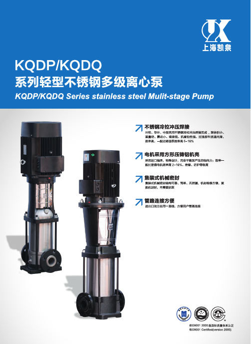
KQDP/KQDQ Series stainless steel Mulit-stage Pump
型号说明
KQDP 65 32 x 6 / 2
KQDQ 65 32 x 6 / 2
安 装 基 础...............................................................................................................50
KQDP、KQDQ系列多级泵型 谱图(50Hz)
H(m) 400 300
KQDP、KQDQ (50Hz)系 列 多 级 泵 型 谱 图...................................................01 产 品 简 介...............................................................................................................02 工 作 条 件...............................................................................................................02 型 号 说 明...............................................................................................................03 水 泵 转 向...............................................................................................................03 电 动 机...................................................................................................................04 轴 封........................................................................................................................04 材 料........................................................................................................................04 性 能 曲 线 说 明......................................................................................................05
上海凯泉水泵选型

上海凯泉水泵选型加工中心和数控机床等设备的大批量生产的过程;产品设计从最初的拿来主义发展为自行开发设计;产品类型也从低温和低压阀门扩展到高温中压、高压和超高压各种专用阀门,以及多种材质、多种驱动方式的各类特殊阀门,具备了相当的配套能力;整个行业的规模逐渐扩大,形成了一个比较健全的阀门制造体系。
但要参与国际市场竞争还要有自己的核心竞争力,既技术、管理、人才、服务与业绩。
前四项是可以通过学习提高的,最后一项业绩是要靠用户支持的,在这方面希望我们的企业家们要有胆识与魄力。
中国的阀门企业要赢得在重大工程中客户的信任一定要有不同于国外企业的营销方式,更要有强大的实力去与之竞争,我相信迅速成长并日益成熟的中国阀门企业会在不远的将来实现令中国人民自豪的这个目标。
本刊记者:知识经济的到来,创新在企业的发展过程中起到什么样的作用?康秘书长:江泽民说过创新是民族进步的灵魂,是国家兴【QW(WQ)系列无堵塞潜水排污泵】产品:【QW(WQ)系列无堵塞潜水排污泵】产品简介:QW(WQ)系列无堵塞潜水排污泵是八十年代引进联邦德国ABS制泵公司先进技术的基础上,在我单位科研人员的共同努力下,同时广泛征求国内水泵专家的意见,经多次改良而研制成功的,经测试各项性能指标均达到国外同类产品先进水平。
本排污泵高效节能,结构新颖。
潜水排污泵投放市场后以其独特地功效,可靠的质量受到广大用户的欢迎和好评。
无堵塞潜水泵被许多单位选为代替进口产品,被国家机械委列为重点引进消化项目。
【QW(WQ)系列无堵塞潜水排污泵】型号意义:【QW(WQ)系列无堵塞潜水排污泵】产品特点:1.采用独特的单片或双叶片时轮结构,大大提高了活物通过能力,能有效的通过泵口径的5倍纤维物质与直径为泵口径约50%的固体颗粒2.机械密封采用新型硬质耐腐的软化钨材料,可使泵安全连续运行8000小时以上。
3.整体结构紧凑、体积小、噪声低、节能效果显著,检修方便,无需建泵房,灌入水中即可工作,大大减少工程造价4.该泵密封油室内设置有高精度抗干扰漏水检测传感器,定子绕组内预埋了热敏元件,对水泵电机自动保护。
凯泉api610 8th 数据表
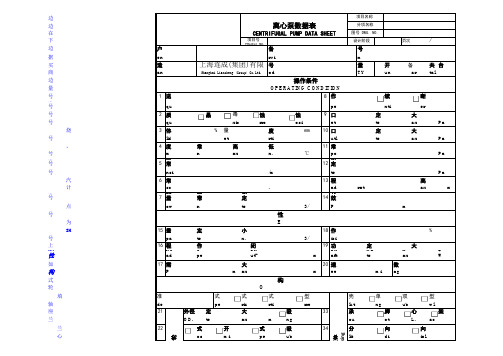
左边是API610第8版的标准数据表,我们现在将两表放在一起进行对比,然后讨论一下如何完成该数据表。
左边很清楚,○此标记表示该项由买方填写根据左边的标识,我们很判断右边哪些内容是买方填写,哪些是卖方填写,哪些是双方协商填写。
右边:序号1输送介质,要写清楚,成分和序号2:介质特性,可重复选项序号3:固体含量(质量含量)序号4:温度一定要准确,影响泵型序号5:密度影响配用电机功率,填得不准小心烧电机序号6:粘度对泵的流量、扬程、效率有影响,具体如何影响,可以查工具书。
序号5、6都是指正常工作温度下的数值。
序号7、8不说了序号9:需要提供,第1要靠这个数值判断泵的汽蚀性能够不够,第2要靠这个数据计算泵最大承压多少序号10、12、13:扬程是等于压差÷密度的这点大家要注意!!序号11:汽化压力,影响汽蚀余量的确定,因为进口压力-汽化压力-安全余量>NPSHr序号14:有效汽蚀余量一般要大于NPSHr 0.5以上操作条件均为买方填写。
泵性能道如何填的或者不知道数据的问技术支持结构里的内容:型式:买方或者卖方填写,双方均须认可。
叶轮、泵体:内容均由卖方提供,不知道怎么填的问技术支持联轴器:可由买方提出要求底座、转向:由买方填写法兰标准号:可以根据泵图纸上的尺寸去查法兰标准上对应的标准号,有时候技术中心也不知道按什么标准设计的,要靠自己查了。
法兰标准可以在网上下。
机械密封:(重点)对化工介质,一般人很难确定机械密封及其冲洗方案。
所以我们通常会把相关内容提供给机械密封厂家,让其协助帮忙选型。
举个例子:上海博格曼。
上海博格曼要求选型前先填写“泵用机械密封设计输入数据单”,见左下第2个工作表。
数据单中“泵数据及结构”按前面的资料填写,“轴(轴套)及密封腔尺寸(mm)”由技术中心提供。
完全填好后,将其做为附件发到bingnian.gao@ (上海博格曼销售 高经理,专门负责连成)Jie.gai@ (上海博格曼技术 盖工)盖工负责根据数据单选型和方案,选好后高经理根据选型报价,所以邮件两人都要发,程序也不能颠倒。
机械密封选型
Seal Material and Arrangement GuideARRANGEMENTSeal Material and Arrangement GuideIntroduction a Step by Step GuideSTAGE 1IDENTIFY FLUID DATASTAGE 3CHECK PERFORMANCELIMITSSTAGE 4CHECK SEAL DIMENSIONSCHECK MATERIAL AVAILABILITYREFER TO PRODUCTDATASHEETSTAGE 2IDENTIFY SEAL TYPESELECTED SEALSUITABLE SEALSThis guide is designed as a quick reference Material and Arrangement guide to complement John Crane CSelect ™Selection routine.When used without CSelect ™then it will be necessary to have the relevant Seal data sheets available to complete the Selection.1IntroductionSelection and ReferenceThis guide is designed to complement John Crane CSelect Seal Selection software. Follow the sequence to find the most effective seal for any of the listed fluids.Stage 1Over 500 commonly found fluids are listed alphabetically in the material guide, only the concentration and temperature of the fluid are needed to find the material, seal arrangement and other installation features.Alternative compatible materials are also shown to allow users who, for special technical or commercial reasons, wish to use materials and/or seal families other than the manuals recommendation, to check that their preference is equally suitable.A key to the Seal Selection page headings is provided on the fold-out page at the back. Stage 2The materials recommended in the material selection pages are the most cost-effective for the particular application. However, suitable seal types may have slightly different standard material combinations.By cross-checking recommended materials from the material selection pages with the standard and optional materials in the material availability chart in the seal data sheets, (not included in this document) appropriate material combinations canbe selected.Seal SelectionCheck ListFluid:.................................................sConcentration:..................................sTemperature:.....................................sSealed Pressure:..............................sShaft/Sleeve Size:............................sShaft Speed:.....................................sSeal Standard:..................................sSeal Chamber Depth:.......................sSeal Chamber Bore:.........................sDistance to NearestObstruction:......................................s 23Worked ExampleStage 3 – Seal Type Performance Evaluation for Seal Data SheetsStage 3 InstructionsUse the pressure/velocity graph and the PV multiplier factors to find the performance limits of the recommended seals.If a dual seal is required then a barrier fluid is needed, please consult John Crane for fluid control systems for tandem and dual seals.The choice of barrier fluid is dependent on individual plantoperating conditions and we recommend that you refer to your local John Crane Field Sales Engineer or John Crane office for specific recommendations.General guidance on barrier fluid selection is given on page 12.Stage 3Check Performance Limits from seal data sheetExample:Fluid: Acetic Acid T emperature: 25°C Pressure: 5 bar gShaft/Sleeve Diameter: 60 mm Speed: 2950 rpmFace/Primary Ring Material: CarbonSeat/Mating Ring Material: Aluminium Oxide CeramicFrom the Pressure/Velocity (PV) Limits chart, the maximum operating pressure at the required shaft sizeis 21 bar g. This pressure has to be corrected by the relevant multipliers from the PV Mulitplier Factors table. In this example the maximum pressure is given by:21 x 0.75 x 0.6 x 1.0 x 0.85 = 8.0 bar gTherefore the application pressure is within the pressure limit of the selected seal.T emperature limits for the bellows and any secondary sealing elements should also be checked to see that the application iswithin material limits.4Worked ExampleStage 4 – Seal Type Dimensional Data from Seal Data SheetsStage 4Check Installation DimensionsExample:Fluid: Acetic AcidShaft/Sleeve Diameter: 60 mm Recommended Seal: T ype 502Stage 4 InstructionsRefer to the relevant dimension tables and check the envelope dimensions to confirm that the sealwill fit the installation.5Key to Selection PagesFluid DataFluid Properties Hazard CodesTOXICCORROSIVEFLAMMABLEWATER REACTIONOXIDISINGEXPLOSIVESPONTANEOUSCOMBUSTION6Installation ArrangementsArrangementWherever possible the recommended sealing solution is a single seal, but if a fluidconcentration and temperature band present a significant hazard, the recommended solution will be for a single seal with a containment device, or, in extreme cases, a dual sealarrangement, with either a pressurised or unpressurised barrier fluid. Dual seal arrangements may also be recommended in cases where there are no suitable materials for a single sealsolution.S – Single SealA single seal mounted internallyA single seal mounted in a stationaryposition with the seat/mating ring rotatingD – Dual SealA dual seal installation where the seals are mounted in a back-to-back configurationwith a pressurised barrier fluid between seals A dual seal installation where the seals are mounted in a tandem configuration with a unpressurised barrier fluid between seals7Key to Selection PagesFlush and Neck ArrangementsFlushA flush is usually clean pumped fluid which is injected into the seal chamber. If necessary, the fluid may pass through a cyclone separator or strainer to ensure that it is clean and free from debris or abrasive matter. Certain applications may require a clean compatible fluid injection from an external source. There are five different seal flush configurations or piping plans, and the recommended flush is stated for each fluid concentration and operating temperature band. API Plan numbers are quoted for each flush configuration in the following examples,and more details of API plans are provided on page 44.F5 – Upstream PumpingA non-pressurised buffer fluid from an external source for use with an Upstream Pumping seal installation. The buffer fluid must be clean and compatible with the fluid being pumped.N1No special neck requirementsN3A moderate neck restriction is required in the form of a close clearance neck bushN4A severe neck restriction is required in the form of a lip seal or similar deviceN2An open large bore or open tapered seal housing is recommendedNeckIn certain circumstances a particular neck arrangement at the inboard end of the seal chamber may be recommended to control the fluid flow in or out of the seal chamber.Existing equipment may require modification to achieve the best seal performance.F1 – No FlushNo seal flush to be installed, i.e. dead ended seal chamber with vent.API Plan 02F2 – Product RecirculationRecirculation of the pumped product either from the pump discharge to the seat/face area of the seal, orfrom the seat/face areas of the seal to the pump suction.API Plans 01, 11, 13 and 21F3 – Clean FlushA flow of clean fluid to the seat/face area of the seal.The fluid can be either pumped fluid recirculated through a strainer or cyclone separator, or a clean compatible fluid from an external source.API Plans 12, 22, 31, 32 and 41F4 – Dual Seal, Pressurised BarrierA pressurised and circulated barrier fluid or gas from an external reservoir for use with a dual seal pressurised arrangement. The barrier fluid must be clean and compatible with the fluid being pumped.API Plans 53A, 53B, 53C, 54, 748Secondary ContainmentSecondary ContainmentAn external seal quench arrangement may be recommended for reasons of either safety, in the form of secondary containment, or to achieve optimum seal performance by use of a liquid or steam quench.The selection pages refer to seven different secondary containment arrangements, and explanations of these are given below.Q1No external quench facility requiredQ2 – Leakage ContainmentA quench gland which is designed to operate as aseal failure control device, diverting leakage to either a safe area drain or to a flare.The minimum requirement for failure control is afixed throttle bush, but its ability to contain liquid or vapour emissions is relatively poor. Dependingupon the fluid to be sealed, it is common practiceto up-grade the method of containment to ahigher integrity device such as an FS Lip Seal, ora floating or segmented bush. These seals can be installed in conjunction with an alarm or other seal failure indicator.For particularly hazardous fluids, it may bepreferable to up-grade the recommended quench arrangement from Q2 to Q6, a dual unpressurised seal arrangement.API Plan 61Q3 – Static QuenchA quench gland with provision for a static clean liquid quench such as an oil barrier.The quench gland should be sealed with a quench containment seal or lip seal, and the liquid level should be maintained at all times by a device such as a constant level oiler.API Plan 51Q4 – Intermittent QuenchA quench gland with provision for an intermittent clean liquid or steam quench.The quench gland should be sealed with a quenchcontainment seal or a lip seal, and the liquid quench flow automatically regulated by a quench control device to minimise wastage of quench liquid. The outlet from thequench gland should be piped to a safe area drain.API Plan 62Q5 – Continuous QuenchA quench gland which is fed with a continuous flow of liquid or steam.The recommended quench gland sealing device for a continuous flow of liquid is either a quench containment seal or a lip seal. For a continuous flow of steam therecommended quench seal is a segmental carbon bush, a floating bush, or a fixed throttle bush. The outlet from the quench gland should be piped to a safe area drain.API Plan 62Q6 – Unpressurised Dual SealAn arrangement where a non-pressurised buffer fluid from an external source is circulated between the inboard and outboard seals. Alternatively, a dry running mechanical containment seal could be used.The outboard seal materials must be suitable for sealing the pumped fluid.API Plans 51 and 52, 72, 75, 76Q7 – Splash GuardExternally mounted seals should be fitted with a splash guard incorporating a drain connection, in order to pipe any splash leakage to a safe area drain.Q2Q3, Q4 and Q5Q6Q7Note:Liquid quenches Q4 and Q5 must be piped in at bottom dead centre of the quench gland andout at top dead centre.Steam quenches Q4 and Q5 must be piped in at top dead centre of the quench gland and out at bottom dead centre.9Selection CommentsWhere appropriate, comments have been added to the selection pages beside the materials suitability chart. The comments are numbered, and a key to them is included on the fold-out page 44. Most of the comments are self-explanatory, but the descriptions for the most commonly used ones are as follows.1Refer to John Crane where no selection shown2Confirm Selection at Very High TemperaturesCertain fluids/applications may require special treatment at very high temperatures -please consult John Crane.3AbrasiveThe sealed fluid is likely to be of an abrasive nature. This has been taken intoaccount by the preferred sealing solution.4Atmospheric DepositsThe sealed fluid may leave deposits on the atmospheric side of the seal. It isrecommended that a Q3, Q4 or Q5 quench be used with an appropriate quenchmedium to prevent accumulation of these deposits.5CrystallisesIndicates that the fluid to be sealed is likely to crystallise on contact withatmosphere.6CloggingCertain fluids may be of a fibrous or abrasive nature, which may under normalcircumstances result in clogging of the seal. This has been taken into account by the preferred sealing solution.7Heated EnvironmentIndicates that the sealed fluid will solidify at normal temperatures, and therefore the pump/seal must be kept hot during operation and should be pre-heated beforeequipment start-up.8Avoid Springs in ProductCertain fluids may be of a fibrous or abrasive nature, which may under normalcircumstances result in clogging of the seal. A seal design where the springs are notimmersed in the fluid is preferred.9Stationary-Mounted SealA stationary-mounted seal with a rotating seat/mating ring is the preferred installationarrangement.10Vortex BreakerThe pump design should include a vortex breaker in the area of the seal.11Q5 – Steam QuenchA steam quench should be used. If the quench medium is not specified, water atambient temperature is recommended.12Q5 – Hot Water QuenchA hot water quench should be used. If the quench medium is not specified, water atambient temperature is recommended.13FDA Materials AvailableFor food-related or hygienic applications, Food and Drug Administration (FDA)approved materials are available and John Crane should be consulted if theseare required.14Refer Refinery SectionRefer to John Crane hydrocarbon processing brochure.15Refer Pulp & Paper SectionRefer to John Crane pulp and paper processing brochure.10Selection Comments16Refer positive Displacement Pump SectionFor positive displacement equipment solutions please refer to John Crane.17Consider Dry Gas SealDry Gas seals may be a more economic solution on this application.18Check Refrigeration Oil MaterialsRefrigeration oils present material compatibility problems, please check compatibility with the materials selected for this application.19Check Refrigeration Fluid MaterialsRefrigeration fluids present material compatibility problems, please checkcompatibility with the materials selected for this application.20Refer to John Crane for Higher Temperatures and Exceptions21Alloy C-276 Acceptable for SpringsSprings and adaptive hardware in Alloy C-276 can be used if indicated. Thin section components such as the edge welded metal bellows are not suitable and should not be used.22Quench fluid contained by a Mech. Seal above 80ºC Refer to John Crane pulp and paper processing brochure.23Dry = >98%Application is dry if concentration exceeds 98%.24Less than 40% GypsumGypsum content to be less than 40% if above consult John Crane.25From Wet ProcessRefer to pure Phosphoric Acid production.26From Thermal ProcessRefer to pure Phosphoric Acid production.27Pressure Surges C4 StageRefer to John Crane pulp and paper processing brochure.28See Seal Data Sheets for specialised face/primary ring materialsSpecialist materials may be appropriate. Consult relevant seal data sheet orbrochure for available materials.29Dry = No water in fluidWater is not present in fluid.30< 2000ppm H2S. Refer to John Crane for higher levels If application contains greater than 2000ppm H2S consult John Crane.11Dual and Multiple SealsIntroductionSelection of Dual SealsWhere a 'D' dual seal configuration isrecommended, it is necessary to select the seal type and materials for the outboard seal in addition to the inboard seal.Pressurised Dual Seals – F4Cross-Section of Pressurised Dual SealInboard Seal – Sealed Liquid SideThe recommended seal family and group material code for the inboard seal will bespecified in the seal selection pages. However,when selecting a seal type from therecommended family, it should be remembered that the operating pressure of the seal will be the difference between the barrier fluid pressure and the sealed fluid pressure. This barrier fluid pressure should be maintained at a minimum of 1 bar g or 10 per cent above the sealed fluid pressure, whichever is the greater – see Chart 1. Due to this low differential pressure, in normal operating conditions it is unlikely that a balanced seal type will be required. If, however, the pump or equipment to be sealed is likely to run dry with a consequential loss of sealed fluid pressure, it is essential that the pressure capability of the selected inboard seal is greater than the maximum pressure of the seal barrier fluid.For most applications it is necessary to ensure that the sealed fluid is contained and barrier fluid contamination minimised. T o achieve this theinboard seal must have a reverse pressureOutboard Seal – Atmosphere Side Generally, the seal family and materials recommended for the inboard seal are also suitable for the outboard seal. However, the pressure of the barrier fluid must be considered and may affect the outboard seal selection.If the sealed fluid is considered to be only moderately hazardous or corrosive it may be possible to select the outboard seal materials to suit the barrier fluid being used in preference to the sealed fluid. This option should only be considered where any migration of sealed fluid into the barrier fluid presents no hazard. If there is any doubt about this, John Crane should be consulted before the selection and use of alternative outboard seal materials.Unpressurised Dual Seals – Q6In the case of non-pressurised dual seals,generally, both inboard and outboard seals used will be of the same family and material code.Cross-Section of Non-Pressurised T andem Seal.Upstream PumpingAn Upstream Pumping seal, which is supplied as a cartridge, is a multiple seal combining the benefits of both a pressurised and a unpressurised dual seal.The materials selected for the inboard seal and the outboard seal should be suitable for the pumped fluid and the buffer fluid used.Ancillary Fluid Control Equipment Both pressurised and unpressurised dual seals require a fluid control system to manage the seal barrier/buffer fluid supply. The requirements of such a system are frequently tailored to suit the application and the operating plant requirements.John Crane should be consulted before theselection and use of any fluid control equipment intended for use on hazardous applications.Barrier Fluids/BufferSelection of a barrier buffer fluid is important to the safe and reliable operation of all dual and seal arrangements.As the fluid selected will be forming the barrier between the sealed fluid and atmosphere, the fluid must be non-hazardous. The fluid must be clean, i.e. not containing debris or abrasivedeposits. It must also be compatible with and at a temperature appropriate for the selected seal materials.In the case of a pressurised dual andUp-Stream Pumping seals, the fluid must also be fully compatible with the sealed fluid because migration of the barrier fluid will occur.Sealant PressureReverse PressureHydraulic Dia.Hydraulic Dia.Figure 11213Seal Material and Arrangement GuideNote 1: Please refer to fold-out page 44i/ii for keyto column headings, codes and comments.Note 2: q = Acceptable.Note 3: Seal performance limits must also be checked.14Seal Material and Arrangement GuideNote 1: Please refer to fold-out page 44i/ii for keyto column headings, codes and comments.Note 2: q = Acceptable.Note 3: Seal performance limits must also be checked.15Seal Material and Arrangement GuideNote 1: Please refer to fold-out page 44i/ii for keyto column headings, codes and comments.Note 2: q = Acceptable.Note 3: Seal performance limits must also be checked.16Seal Material and Arrangement GuideNote 1: Please refer to fold-out page 44i/ii for keyto column headings, codes and comments.Note 2: q = Acceptable.Note 3: Seal performance limits must also be checked.17Seal Material and Arrangement GuideNote 1: Please refer to fold-out page 44i/ii for keyto column headings, codes and comments.Note 2: q = Acceptable.Note 3: Seal performance limits must also be checked.18Seal Material and Arrangement GuideNote 1: Please refer to fold-out page 44i/ii for keyto column headings, codes and comments.Note 2: q = Acceptable.Note 3: Seal performance limits must also be checked.19Seal Material and Arrangement GuideNote 1: Please refer to fold-out page 44i/ii for keyto column headings, codes and comments.Note 2: q = Acceptable.Note 3: Seal performance limits must also be checked.Seal Material and Arrangement GuideNote 1: Please refer to fold-out page 44i/ii for keyto column headings, codes and comments.Note 2: q = Acceptable.Note 3: Seal performance limits must also be checked.Seal Material and Arrangement GuideNote 1: Please refer to fold-out page 44i/ii for keyto column headings, codes and comments.Note 2: q = Acceptable.Note 3: Seal performance limits must also be checked.Seal Material and Arrangement GuideNote 1: Please refer to fold-out page 44i/ii for keyto column headings, codes and comments.Note 2: q = Acceptable.Note 3: Seal performance limits must also be checked.Seal Material and Arrangement GuideNote 1: Please refer to fold-out page 44i/ii for keyto column headings, codes and comments.Note 2: q = Acceptable.Note 3: Seal performance limits must also be checked.Seal Material and Arrangement GuideNote 1: Please refer to fold-out page 44i/ii for keyto column headings, codes and comments.Note 2: q = Acceptable.Note 3: Seal performance limits must also be checked.30Seal Material and Arrangement GuideNote 1: Please refer to fold-out page 44i/ii for keyto column headings, codes and comments.Note 2: q = Acceptable.Note 3: Seal performance limits must also be checked.32Seal Material and Arrangement GuideNote 1: Please refer to fold-out page 44i/ii for keyto column headings, codes and comments.Note 2: q = Acceptable.Note 3: Seal performance limits must also be checked.34Seal Material and Arrangement GuideNote 1: Please refer to fold-out page 44i/ii for keyto column headings, codes and comments.Note 2: q = Acceptable.Note 3: Seal performance limits must also be checked.36Seal Material and Arrangement GuideNote 1: Please refer to fold-out page 44i/ii for keyto column headings, codes and comments.Note 2: q = Acceptable.Note 3: Seal performance limits must also be checked.38Seal Material and Arrangement GuideNote 1: Please refer to fold-out page 44i/ii for keyto column headings, codes and comments.Note 2: q = Acceptable.Note 3: Seal performance limits must also be checked.40Seal Material and Arrangement GuideNote 1: Please refer to fold-out page 44i/ii for keyto column headings, codes and comments.Note 2: q = Acceptable.Note 3: Seal performance limits must also be checked.41Seal Material and Arrangement GuideNote 1: Please refer to fold-out page 44i/ii for keyto column headings, codes and comments.Note 2: q = Acceptable.Note 3: Seal performance limits must also be checked.42Seal Material and Arrangement GuideNote 1: Please refer to fold-out page 44i/ii for keyto column headings, codes and comments.Note 2: q = Acceptable.Note 3: Seal performance limits must also be checked.43Seal Material and Arrangement GuideNote 1: Please refer to fold-out page 44i/ii for keyto column headings, codes and comments.Note 2: q = Acceptable.Note 3: Seal performance limits must also be checked.44ivFind the temperature you want to convert (°C or °F) in the centre column (heavy type).Temperature Conversion Table45Inch Seal SizesSeal Size CodesMetric Seal Sizes。
凯泉第六代KQL KQW单级泵电机样本
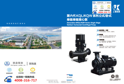
泵与电机直接连接,外形美观,占地面积小
闭式铸铁叶轮,优秀的水力模型保证泵的 高效 和节能,大部分型号泵的配套功率下降一档
SKF 轴承配置合理,叶轮悬臂端,机泵轴完全 同心,泵运行平稳、可靠,噪音低
密封位不锈钢,永不生锈,强制环流冲洗进口 品牌机械密封,免保养、无渗漏、3年免维护
地址:上海市嘉定区曹安公路4255号/4287号 集团呼叫中心:400-002-6600 http: //
型号配置 MODEL 主要部件 MAIN PARTS
电机系列 MOTOR
泵轴材料 SHAFT
轴承 BEARING
机械密封 MECHANCAL
SEAL
铸件 CASTING
表面处理 SURFACE DISPOSE
KQL 或 KQW
YE2系列超高效率三相异步电动机 Three-phase induction motor series
YB/KAIQUAN KQL/KQW 06 20190909
销售热线:4008-316-717
2015
2015
凯泉与SKF战略合作
SKF根植中国,凯泉走向世界!
凯泉成为全球率先允许在设备上使用SKF Equipped商标的企业!
上海凯泉是集设计/生产/销售泵、给水设备及泵用控制设备于一体的大型综合性泵业集团, 是中国泵行业的龙头企业。集团现有员工4500多人,其中工程技术人员750多名,主要由知名 水泵专家教授、博士硕士、中高级工程师构成,形成了具有创新思维的梯队人才结构。在上 海、浙江、河北、辽宁、安徽等省市拥有7家企业,5个工业园区。上海凯泉集团获得了“上海 市科技百强企业”、“上海市名牌产品”、“中国质量信用AAA级”、“全国合同信用等级 AAA级争力的商品商标”等光荣称号,至 今名列泵行业之首。
上海凯泉WFY标准说明书文本
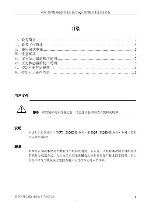
目录一、设备简介 (2)二、设备工作原理 (3)三、使用调试步骤 (6)四、注意事项 (7)五、文本显示器的操作说明 (7)六、压力传感器的使用说明 (10)七、控制柜电气原理图 (11)八、控制柜元器件清单 (15)用户文件———————————————————————————————————警告在安装和调试设备之前,请您务必仔细阅读本使用说明书———————————————————————————————————说明本说明手册仅适用于WFY(KQK500系列)和KQF(KQK600系列)两种电控柜的安装与调试!联系如果您在阅读本说明书时有什么疑问或遇到任何问题,请根据本说明书封面提供的地址及联系方式,与上海凯泉泵业集团供水事业部四分厂技术四室联系。
非工作时间请先与凯泉泵业集团当地分公司技术支持人员联系。
一、设备简介为充分满足不同地区各类客户的不同需求,上海凯泉供水事业部共设计了四大系列共四千多种规格的自动供水设备。
在控制功能上分为二大类:间歇性供水和连续性供水。
间歇性供水设备带有气压罐,出厂设置为能够自动停机,适应于间歇性供水的场合;既满足供水的适时性,又可以最大限度的节能。
连续性供水设备一般不设置自动停机,用水量较小时采用变频低频节能运行,通常适用于供水流量较大或流量较稳定的用户。
WFY、KQF两种新型智能供水设备,是在原KQG供水设备的基础上采用通用控制系统开发而来,所谓“通用”即不依赖变频器的特有功能(可换用任意厂商的变频器)。
其设计完全符合中华人民共和国城镇建设行业标准《管网叠压供水设备》(CJ/T 254-2007)和中国工程建设标准化协会标准《管网叠压供水技术规程》(CECS 221:2007)的相关要求。
该设备能够充分利用市政管网原有压力,采取“差多少补多少”的增压方式,实现节能、环保、卫生等效果,现正式称为“管网叠压供水设备”,早期商品名为“无负压(无吸程)给水设备”。
客户应根据实际需求选用WFY或KQF系列设备。
- 1、下载文档前请自行甄别文档内容的完整性,平台不提供额外的编辑、内容补充、找答案等附加服务。
- 2、"仅部分预览"的文档,不可在线预览部分如存在完整性等问题,可反馈申请退款(可完整预览的文档不适用该条件!)。
- 3、如文档侵犯您的权益,请联系客服反馈,我们会尽快为您处理(人工客服工作时间:9:00-18:30)。
t<80℃ p<2.5MPa 材料 方案 SGV88/2 SGV88/2 SGV88/2 SGV88/2 SGV88/2 SGV88/2 SGV88/2 SGV88/2 SGV88/2 SGV88/2 SGV88/2 SGV88/2 SGV88/2 SGV88/2 SGV88/2 SGV88/2 SGV88/2 SGV88/2 SGV88/2 SGV88/2 SGV88/2 SGV88/2 SGV88/2 SGV88/2 SGV88/2 SGV88/2 SGV88/2
机封型号 C8B-50/TP C8B-50/TP C8B-50/TP C8B-50/TP C8B-50/TP C8B-50/TP C8B-50/TP C8B-50/TP C8B-60/TP C8B-60/TP C8B-60/TP C8B-60/TP C8B-60/TP C8B-85/TP C8B-85/TP C8B-85/TP C8B-85/TP C8B-90/TP C8B-90/TP C8B-90/TP C8B-90/TP C8B-50/TP C8B-50/TP C8B-65/TP C8B-65/TP C8B-75/TP C8B-75/TP
备注 11 11 11 11 11 11 11 11 11 11 11 1 11 11 11 11 11 11 11 11 11 11 11 11 11 11 11
机封型号 C8B-50/TP C8B-50/TP C8B-50/TP C8B-50/TP C8B-50/TP C8B-50/TP C8B-50/TP C8B-50/TP C8B-60/TP C8B-60/TP C8B-60/TP C8B-60/TP C8B-60/TP C8B-85/TP C8B-85/TP C8B-85/TP C8B-85/TP C8B-90/TP C8B-90/TP C8B-90/TP C8B-90/TP C8B-50/TP C8B-50/TP C8B-65/TP C8B-65/TP C8B-75/TP C8B-75/TP
悬臂式 悬臂式 悬臂式 悬臂式 悬臂式 悬臂式 悬臂式 悬臂式 悬臂式 悬臂式 悬臂式 悬臂式 悬臂式 悬臂式 悬臂式 悬臂式 悬臂式 双支撑式 双支撑式 双支撑式 双支撑式 多级泵 多级泵 多级泵 多级泵 多级泵 多级泵
泵型号 40AY40T×2 50AY60T×2 50AY60 65AY60 65AY100 80AY60 80AY100 100AY60 65AY100×2 80AY100×2 100AY120 150AY75 200AY75 100AY120×2 150AY150 200AY150 250AYS80 150AY150×2 200AY150×2 250AYS150 250AYS150×2 40AY35T×3-12 50AY35T×4-12 80AY50×5-12 65AY50×5-12 150AY67×6-9 100AY67×5-9
介质:水,无腐蚀 使用条件 80℃<t<120℃ p<2.5MPa 材料 方案 备注 SGV88/2 21 HR04 SGV88/2 21 HR04 SGV88/2 21 HR04 SGV88/2 21 HR04 SGV88/2 21 HR04 SGV88/2 21 HR04 SGV88/2 21 HR04 SGV88/2 21 HR04 SGV88/2 21 HR04 SGV88/2 21 HR04 SGV88/2 21 HR04 SGV88/2 21 HR04 SGV88/2 21 HR04 SGV88/2 21 HR06 SGV88/2 21 HR06 SGV88/2 21 HR06 SGV88/2 21 HR06 SGV88/2 21 HR06 SGV88/2 21 HR06 SGV88/2 21 HR06 SGV88/2 21 HR06 SGV88/2 21 HR04 SGV88/2 21 HR04 SGV88/2 21 HR04 SGV88/2 21 HR04 SGV88/2 21 HR06 SGV88/2 21 HR06
℃ p<2.5MPa 备注 HR04, HR04, HR04, HR04, HR04, HR04, HR04, HR04, HR04, HR04, HR04, HR04, HR04, HR06,23方案采用HR04 HR06,23方案采用HR04 HR06,23方案采用HR04 HR06,23方案采用HR04 HR06,23方案采用HR04 HR06,23方案采用HR04 HR06,23方案采用HR04 HR06,23方案采用HR04 HR04, HR04, HR04, HR04, HR06,23方案采用HR04 HR06,23方案采用HR04
机封型号 C8BKC-50/TP C8BKC-50/TP C8BKC-50/TP C8BKC-50/TP C8BKC-50/TP C8BKC-50/TP C8BKC-50/TP C8BKC-50/TP C8BKC-60/TP C8BKC-60/TP C8BKC-60/TP C8BKC-60/TP C8BKC-60/TP C8BKC-85/TP C8BKC-85/TP C8BKC-85/TP C8BKC-85/TP C8BKC-90/TP C8BKC-90/TP C8BKC-90/TP C8BKC-90/TP C8BKC-50/TP C8BKC-50/TP C8BKC-65/TP C8BKC-65/TP C8BKC-75/TP C8BKC-75/TP
120℃<t<150℃ p<2.5MPa 材料 方案 SGV88/2 21或23含有泵送环 SGV88/2 21或23含有泵送环 SGV88/2 21或23含有泵送环 SGV88/2 21或23含有泵送环 SGV88/2 21或23含有泵送环 SGV88/2 21或23含有泵送环 SGV88/2 21或23含有泵送环 SGV88/2 21或23含有泵送环 SGV88/2 21或23含有泵送环 SGV88/2 21或23含有泵送环 SGV88/2 21或23含有泵送环 SGV88/2 21或23含有泵送环 SGV88/2 21或23含有泵送环 SGV88/2 21或23含有泵送环 SGV88/2 21或23含有泵送环 SGV88/2 21或23含有泵送环 SGV88/2 21或23含有泵送环 SGV88/2 21或23含有泵送环 SGV88/2 21或23含有泵送环 SGV88/2 21或23含有泵送环 SGV88/2 21或23含有泵送环 SGV88/2 21或23含有泵送环 SGV88/2 21或23含有泵送环 SGV88/2 21或23含有泵送环 SGV88/2 21或23含有泵送环 SGV88/2 21或23含有泵送环 SGV88/2 21或23含有泵送环