Innovation of “Workshop” Mode in Modern Practice Teaching of Environmental Design Major
unable to toggle developer mode on headset -回复

unable to toggle developer mode on headset-回复如何在头戴设备上切换开发者模式开发者模式是一种允许用户自定义设置和进行高级操作的模式,通常在头戴设备(如虚拟现实设备或增强现实设备)上使用。
然而,有时候用户可能会遇到无法切换到开发者模式的问题。
在本篇文章中,我们将一步步回答如何解决头戴设备无法切换开发者模式的问题。
第一步:初步检查首先,我们需要对头戴设备进行初步检查,确保没有硬件问题。
请检查以下几点:1. 确保头戴设备的电源已经打开,充足的电量可以确保设备正常运行。
2. 检查连接头戴设备的电缆是否牢固连接。
有时候,松动的连接可能导致开发者模式无法切换。
3. 检查设备的固件版本。
某些旧版本的固件可能没有开发者模式选项或在使用上有限制。
如果需要更新固件,请参考设备的制造商手册或官方网站的说明。
第二步:检查设备设置如果头戴设备已经通过初步检查,接下来我们需要检查设备的设置。
根据设备的型号和品牌,步骤可能会略有不同。
下面是一些常见的设置检查点:1. 打开设备的设置菜单,查找开发者选项。
在某些设备上,开发者选项可能需要手动启用。
通常,您可以在“关于设备”或“设备信息”菜单中找到该选项。
2. 在开发者选项菜单中,查找“USB调试”选项。
开启USB调试可以使设备与开发者工具(如计算机中的Android开发工具)进行通信。
确保此选项已启用。
3. 检查其他与开发者模式相关的选项,如“模拟位置”或“不锁定屏幕”。
启用这些选项可以提供更多的自定义设置和功能。
第三步:重启设备和开发者工具如果您仍然无法在头戴设备上切换到开发者模式,下一步是尝试重新启动设备和相关的开发者工具。
请按照以下步骤进行操作:1. 关闭头戴设备并将其与计算机或其他设备断开连接。
2. 关闭任何与设备相关的开发者工具,如Android开发工具(ADB)或虚拟机软件。
3. 重新启动设备和开发者工具。
首先启动头戴设备,然后重新连接到计算机或其他设备上。
SINUMERIK 828D 多触屏操作手册说明书

SINUMERIK SINUMERIK 828D MillingOperating ManualValid for:SINUMERIK 828DSoftware versionCNC system software for 828D V4.95 SINUMERIK Operate for PCU/PC V4.9507/20216FC5398-7CP41-0BA1Legal information Warning notice systemThis manual contains notices you have to observe in order to ensure your personal safety, as well as to prevent damage to property. The notices referring to your personal safety are highlighted in the manual by a safety alert symbol, notices referring only to property damage have no safety alert symbol. These notices shown below are graded according tothe degree of danger.DANGERindicates that death or severe personal injury will result if proper precautions are not taken.WARNINGindicates that death or severe personal injury may result if proper precautions are not taken.CAUTIONindicates that minor personal injury can result if proper precautions are not taken.NOTICEindicates that property damage can result if proper precautions are not taken.If more than one degree of danger is present, the warning notice representing the highest degree of danger will be used. A notice warning of injury to persons with a safety alert symbol may also include a warning relating to property damage.Qualified PersonnelThe product/system described in this documentation may be operated only bypersonnel qualified for the specific task in accordance with the relevant documentation, in particular its warning notices and safety instructions. Qualified personnel are those who, based on their training and experience, are capable of identifying risks and avoiding potential hazards when working with these products/systems.Proper use of Siemens productsNote the following:WARNINGSiemens products may only be used for the applications described in the catalog and in the relevant technical documentation. If products and components from other manufacturers are used, these must be recommended or approved by Siemens. Proper transport, storage, installation, assembly, commissioning, operation and maintenance are required to ensure that the products operate safely and without any problems. The permissible ambient conditions must be complied with. The information in the relevant documentation must be observed.TrademarksAll names identified by ® are registered trademarks of Siemens AG. The remaining trademarks in this publication may be trademarks whose use by third parties for their own purposes could violate the rights of the owner.Disclaimer of LiabilityWe have reviewed the contents of this publication to ensure consistency with the hardware and software described. Since variance cannot be precluded entirely, we cannot guarantee full consistency. However, the information in this publication is reviewed regularly and any necessary corrections are included in subsequent editions.Siemens AGDigital Industries Postfach 48 4890026 NÜRNBERG GERMANYDocument order number: 6FC5398-7CP41-0BA1Ⓟ 06/2021 Subject to change Copyright © Siemens AG 2008 - 2021.All rights reservedTable of contents1Introduction (19)1.1About SINUMERIK (19)1.2About this documentation (20)1.3Documentation on the internet (22)1.3.1Documentation overview SINUMERIK 828D (22)1.3.2Documentation overview SINUMERIK operator components (22)1.4Feedback on the technical documentation (24)1.5mySupport documentation (25)1.6Service and Support (26)1.7Important product information (28)2Fundamental safety instructions (29)2.1General safety instructions (29)2.2Warranty and liability for application examples (30)2.3Security information (31)3Fundamentals (33)3.1Product overview (33)3.2Operator panel fronts (34)3.2.1Overview (34)3.2.2Keys of the operator panel (36)3.3Machine control panels (44)3.3.1Overview (44)3.3.2Controls on the machine control panel (44)3.4User interface (48)3.4.1Screen layout (48)3.4.2Status display (49)3.4.3Actual value window (51)3.4.4T,F,S window (53)3.4.5Operation via softkeys and buttons (55)3.4.6Entering or selecting parameters (56)3.4.7Pocket calculator (58)3.4.8Pocket calculator functions (59)3.4.9Context menu (61)3.4.10Changing the user interface language (61)3.4.11Entering Chinese characters (62)3.4.11.1Function - input editor (62)3.4.11.2Entering Asian characters (64)3.4.11.3Editing the dictionary (65)3.4.12Entering Korean characters (66)MillingOperating Manual, 07/2021, 6FC5398-7CP41-0BA13Table of contents3.4.13Protection levels (69)3.4.14Work station safety (71)3.4.15Cleaning mode (71)3.4.16Online help in SINUMERIK Operate (71)4Multitouch operation with SINUMERIK Operate (75)4.1Multitouch panels (75)4.2Touch-sensitive user interface (76)4.3Finger gestures (77)4.4Multitouch user interface (80)4.4.1Screen layout (80)4.4.2Function key block (81)4.4.3Further operator touch controls (81)4.4.4Virtual keyboard (82)4.4.5Special "tilde" character (83)4.5Expansion with side screen (84)4.5.1Overview (84)4.5.2Sidescreen with standard windows (84)4.5.3Standard widgets (86)4.5.4"Actual value" widget (86)4.5.5"Zero point" widget (87)4.5.6"Alarms" widget (87)4.5.7"NC/PLC variables" widget (87)4.5.8"Axle load" widget (88)4.5.9"Tool" widget (88)4.5.10"Service life" widget (89)4.5.11"Program runtime" widget (89)4.5.12Widget "Camera 1" and "Camera 2" (89)4.5.13Sidescreen with pages for the ABC keyboard and/or machine control panel (90)4.5.14Example 1: ABC keyboard in the sidescreen (91)4.5.15Example 2: Machine control panel in the sidescreen (92)5Setting up the machine (93)5.1Switching on and switching off (93)5.2Approaching a reference point (94)5.2.1Referencing axes (94)5.2.2User agreement (95)5.3Operating modes (97)5.3.1General (97)5.3.2Modes groups and channels (99)5.3.3Channel switchover (99)5.4Settings for the machine (101)5.4.1Switching over the coordinate system (MCS/WCS) (101)5.4.2Switching the unit of measurement (101)5.4.3Setting the zero offset (103)5.5Measure tool (105)5.5.1Overview (105)5.5.2Manually measuring drilling and milling tools (105)Milling 4Operating Manual, 07/2021, 6FC5398-7CP41-0BA1Table of contents5.5.3Measuring drilling and milling tools with the workpiece reference point (106)5.5.4Measuring drilling and milling tools with fixed reference point (107)5.5.5Measuring radius or diameter (108)5.5.6Fixed point calibration (109)5.5.7Measuring the drilling and milling tool length with electrical tool probe (109)5.5.8Calibrating the electrical tool probe (112)5.5.9Manually measuring a turning tool (for milling/turning machine) (113)5.5.10Manually measuring a turning tool using a tool probe (for milling/turning machine) (114)5.5.11Logging tool measurement results (116)5.6Measuring the workpiece zero (117)5.6.1Overview (117)5.6.2Sequence of operations (121)5.6.3Examples with manual swiveling (swiveling in JOG mode) (122)5.6.4Setting the edge (123)5.6.5Edge measurement (124)5.6.6Measuring a corner (129)5.6.7Measuring a pocket and hole (132)5.6.8Measuring a spigot (135)5.6.9Aligning the plane (140)5.6.10Defining the measurement function selection (142)5.6.11Logging measurement results for the workpiece zero (143)5.6.12Calibrating the electronic workpiece probe (144)5.6.12.1Calibration of length and radius or diameter (144)5.6.12.2Calibrate on sphere (146)5.7Settings for the measurement result log (148)5.8Zero offsets (150)5.8.1Overview - work offsets (150)5.8.2Display active zero offset (151)5.8.3Displaying the zero offset "overview" (151)5.8.4Displaying and editing base zero offset (153)5.8.5Displaying and editing settable zero offset (154)5.8.6Displaying and editing details of the zero offsets (154)5.8.7Deleting a zero offset (156)5.8.8Measuring the workpiece zero (157)5.9Monitoring axis and spindle data (158)5.9.1Specify working area limitations (158)5.9.2Editing spindle data (158)5.10Displaying setting data lists (160)5.11Handwheel assignment (161)5.12MDA (163)5.12.1Working in MDA (163)5.12.2Saving an MDA program (163)5.12.3Editing/executing a MDI program (164)5.12.4Deleting an MDA program (165)6Execution in manual mode (167)6.1General (167)6.2Selecting a tool and spindle (168)MillingOperating Manual, 07/2021, 6FC5398-7CP41-0BA15Table of contents6.2.1T, S, M windows (168)6.2.2Selecting a tool (170)6.2.3Starting and stopping a spindle manually (170)6.2.4Position spindle (171)6.3Traversing axes (173)6.3.1Traverse axes by a defined increment (173)6.3.2Traversing axes by a variable increment (174)6.4Positioning axes (175)6.5Swiveling (176)6.6Manual retraction (181)6.7Simple face milling of the workpiece (183)6.8Simple workpiece machining operations with milling/turning machines (186)6.8.1Simple workpiece face milling (milling/turning machine) (186)6.8.2Simple stock removal of workpiece (for milling/turning machine) (188)6.9Default settings for manual mode (192)7Machining the workpiece (193)7.1Starting and stopping machining (193)7.2Selecting a program (195)7.3Testing a program (196)7.4Displaying the current program block (197)7.4.1Displaying a basic block (197)7.4.2Display program level (197)7.5Correcting a program (199)7.6Repositioning axes (200)7.7Starting machining at a specific point (201)7.7.1Use block search (201)7.7.2Continuing program from search target (203)7.7.3Simple search target definition (203)7.7.4Defining an interruption point as search target (204)7.7.5Entering the search target via search pointer (205)7.7.6Parameters for block search in the search pointer (206)7.7.7Block search mode (206)7.7.8Block search for position pattern (208)7.8Controlling the program run (210)7.8.1Program control (210)7.8.2Skip blocks (211)7.9Overstore (213)7.10Editing a program (215)7.10.1Searching in programs (215)7.10.2Replacing program text (217)7.10.3Copying/pasting/deleting a program block (218)7.10.4Renumbering a program (220)7.10.5Creating a program block (220)Milling 6Operating Manual, 07/2021, 6FC5398-7CP41-0BA1Table of contents7.10.6Opening additional programs (222)7.10.7Editor settings (223)7.11Working with DXF files (227)7.11.1Overview (227)7.11.2Displaying CAD drawings (228)7.11.2.1Open a DXF file (228)7.11.2.2Cleaning a DXF file (228)7.11.2.3Enlarging or reducing the CAD drawing (229)7.11.2.4Changing the section (230)7.11.2.5Rotating the view (230)7.11.2.6Displaying/editing information for the geometric data (231)7.11.3Importing and editing a DXF file in the editor (232)7.11.3.1General procedure (232)7.11.3.2Specifying a reference point (232)7.11.3.3Assigning the machining plane (233)7.11.3.4Setting the tolerance (233)7.11.3.5Selecting the machining range / deleting the range and element (233)7.11.3.6Saving the DXF file (235)7.11.3.7Transferring the drilling positions (235)7.11.3.8Accepting contours (238)7.12Importing shapes from CAD programs (241)7.12.1Reading in CAD data into an editor and processing (243)7.12.1.1General procedure (243)7.12.1.2Import from CAD (243)7.12.1.3Defining reference points (244)7.12.1.4Accepting the machining steps (246)7.13Display and edit user variables (248)7.13.1Overview (248)7.13.2Global R parameters (249)7.13.3R parameters (250)7.13.4Displaying global user data (GUD) (252)7.13.5Displaying channel GUDs (253)7.13.6Displaying local user data (LUD) (254)7.13.7Displaying program user data (PUD) (255)7.13.8Searching for user variables (255)7.14Displaying G Functions and Auxiliary Functions (258)7.14.1Selected G functions (258)7.14.2All G functions (260)7.14.3G functions for mold making (260)7.14.4Auxiliary functions (261)7.15Displaying superimpositions (263)7.16Mold making view (266)7.16.1Overview (266)7.16.2Starting the mold making view (268)7.16.3Adapting the mold making view (268)7.16.4Specifically jump to the program block (269)7.16.5Searching for program blocks (270)7.16.6Changing the view (271)7.16.6.1Enlarging or reducing the graphical representation (271)MillingOperating Manual, 07/2021, 6FC5398-7CP41-0BA17Table of contents7.16.6.2Moving and rotating the graphic (272)7.16.6.3Modifying the viewport (272)7.17Displaying the program runtime and counting workpieces (274)7.18Setting for automatic mode (276)8Simulating machining (279)8.1Overview (279)8.2Simulation before machining of the workpiece (287)8.3Simultaneous recording before machining of the workpiece (288)8.4Simultaneous recording during machining of the workpiece (289)8.5Different views of the workpiece (290)8.5.1Plan view (290)8.5.23D view (291)8.5.3Side view (291)8.5.4Turning view (292)8.5.5Half section (292)8.6Editing the simulation display (294)8.6.1Blank display (294)8.6.2Showing and hiding the tool path (294)8.7Program control during the simulation (295)8.7.1Changing the feedrate (295)8.7.2Simulating the program block by block (296)8.8Changing and adapting a simulation graphic (297)8.8.1Enlarging or reducing the graphical representation (297)8.8.2Panning a graphical representation (298)8.8.3Rotating the graphical representation (298)8.8.4Modifying the viewport (299)8.8.5Defining cutting planes (299)8.9Displaying simulation alarms (301)9Generating a G code program (303)9.1Graphical programming (303)9.2Program views (304)9.3Program structure (308)9.4Fundamentals (309)9.4.1Machining planes (309)9.4.2Current planes in cycles and input screens (309)9.4.3Programming a tool (T) (310)9.5Generating a G code program (311)9.6Blank input (312)9.7Machining plane, milling direction, retraction plane, safe clearance and feedrate (PL, RP,SC, F) (314)9.8Selection of the cycles via softkey (315)Milling 8Operating Manual, 07/2021, 6FC5398-7CP41-0BA1Table of contents9.9Calling technology functions (319)9.9.1Hiding cycle parameters (319)9.9.2Setting data for cycles (319)9.9.3Checking cycle parameters (319)9.9.4Programming variables (320)9.9.5Changing a cycle call (320)9.9.6 Compatibility for cycle support (321)9.9.7Additional functions in the input screens (321)9.10Measuring cycle support (322)10Creating a ShopMill program (323)10.1Program views (324)10.2Program structure (329)10.3Fundamentals (330)10.3.1Machining planes (330)10.3.2Polar coordinates (330)10.3.3Absolute and incremental dimensions (331)10.4Creating a ShopMill program (334)10.5Program header (335)10.6Program header (for milling/turning machine) (337)10.7Generating program blocks (340)10.8Tool, offset value, feed and spindle speed (T, D, F, S, V) (341)10.9Defining machine functions (343)10.10Call work offsets (345)10.11Repeating program blocks (346)10.12Specifying the number of workpieces (348)10.13Changing program blocks (349)10.14Changing program settings (350)10.15Selection of the cycles via softkey (352)10.16Calling technology functions (357)10.16.1Additional functions in the input screens (357)10.16.2Checking input parameters (357)10.16.3Setting data for technological functions (357)10.16.4Changing a cycle call (358)10.16.5Programming variables (358)10.16.6 Compatibility for cycle support (359)10.17Measuring cycle support (360)10.18Example, standard machining (361)10.18.1Workpiece drawing (362)10.18.2Programming (362)10.18.3Results/simulation test (373)10.18.4G code machining program (375)MillingOperating Manual, 07/2021, 6FC5398-7CP41-0BA19Table of contents11Programming technological functions (cycles) (379)11.1Know-how protection (379)11.2Drilling (380)11.2.1General (380)11.2.2Centering (CYCLE81) (381)11.2.3Drilling (CYCLE82) (382)11.2.4Reaming (CYCLE85) (386)11.2.5Deep-hole drilling 1 (CYCLE83) (387)11.2.6Deep-hole drilling 2 (CYCLE830) (393)11.2.7Boring (CYCLE86) (403)11.2.8Tapping (CYCLE84, 840) (405)11.2.9Drill and thread milling (CYCLE78) (412)11.2.10Positioning and position patterns (416)11.2.11Arbitrary positions (CYCLE802) (418)11.2.12Row position pattern (HOLES1) (421)11.2.13Grid or frame position pattern (CYCLE801) (422)11.2.14Circle or pitch circle position pattern (HOLES2) (424)11.2.15Displaying and hiding positions (426)11.2.16Repeating positions (428)11.3Milling (429)11.3.1Face milling (CYCLE61) (429)11.3.2Rectangular pocket (POCKET3) (431)11.3.3Circular pocket (POCKET4) (438)11.3.4Rectangular spigot (CYCLE76) (445)11.3.5Circular spigot (CYCLE77) (450)11.3.6Multi-edge (CYCLE79) (454)11.3.7Longitudinal groove (SLOT1) (458)11.3.8Circumferential groove (SLOT2) (464)11.3.9Open groove (CYCLE899) (470)11.3.10Long hole (LONGHOLE) - only for G code programs (479)11.3.11Thread milling (CYCLE70) (481)11.3.12Engraving (CYCLE60) (485)11.4Contour milling (492)11.4.1General (492)11.4.2Representation of the contour (492)11.4.3Creating a new contour (494)11.4.4Creating contour elements (495)11.4.5Changing the contour (500)11.4.6Contour call (CYCLE62) - only for G code program (501)11.4.7Path milling (CYCLE72) (502)11.4.8Contour pocket/contour spigot (CYCLE63/64) (507)11.4.9Predrilling contour pocket (CYCLE64) (509)11.4.10Milling contour pocket (CYCLE63) (512)11.4.11Residual material contour pocket (CYCLE63) (517)11.4.12Milling contour spigot (CYCLE63) (518)11.4.13Residual material contour spigot (CYCLE63) (522)11.5Turning - milling/turning machine (525)11.5.1General (525)11.5.2Stock removal (CYCLE951) (525)Milling 10Operating Manual, 07/2021, 6FC5398-7CP41-0BA1Table of contents 11.5.3Groove (CYCLE930) (529)11.5.4Undercut form E and F (CYCLE940) (533)11.5.5Thread undercut (CYCLE940) (539)11.5.6Thread turning (CYCLE99), only for G code (545)11.5.6.1Special aspects of the selection alternatives for infeed depths (572)11.5.7Thread chain (CYCLE98) (573)11.5.7.1Special aspects of the selection alternatives for infeed depths (582)11.5.8Cut-off (CYCLE92) (583)11.6Contour turning - Milling/turning machine (587)11.6.1General information (587)11.6.2Representation of the contour (588)11.6.3Creating a new contour (589)11.6.4Creating contour elements (591)11.6.5Changing the contour (597)11.6.6Contour call (CYCLE62) (598)11.6.7Stock removal (CYCLE952) (599)11.6.8Stock removal residual (CYCLE952) (614)11.6.9Grooving (CYCLE952) (617)11.6.10Grooving residual material (CYCLE952) (628)11.6.11Plunge turning (CYCLE952) (632)11.6.12Plunge turning residual material (CYCLE952) (642)11.7Further cycles and functions (647)11.7.1Swivel plane (CYCLE800) (647)11.7.1.1Cylinder surface transformation with swivel plane (654)11.7.2Swiveling tool (CYCLE800) (658)11.7.2.1Swiveling tool/preloading milling tools - only for G code program (CYCLE800) (658)11.7.2.2Aligning turning tools (CYCLE800) - millling/turning machine (659)11.7.3High-speed settings (CYCLE832) (664)11.7.4Subroutines (668)11.7.5Surface turning (CYCLE953) (670)11.7.6Adapt to load (CYCLE782) (672)11.7.7Interpolation turning (CYCLE806) (674)11.7.7.1Function (674)11.7.7.2Selecting/deselecting interpolation turning - CYCLE806 (675)11.7.7.3Calling the cycle (676)11.7.7.4Parameter (676)11.8Additional cycles and functions in ShopMill (677)11.8.1Transformations (677)11.8.2Translation (678)11.8.3Rotation (678)11.8.4Scaling (679)11.8.5Mirroring (680)11.8.6Cylinder surface transformation (680)11.8.7Straight or circular machining (683)11.8.8Programming a straight line (685)11.8.9Programming a circle with known center point (686)11.8.10Programming a circle with known radius (687)11.8.11Helix (688)11.8.12Polar coordinates (689)11.8.13Straight polar (690)11.8.14Circle polar (691)Table of contents11.8.15Obstacle (692)12Multi-channel view (695)12.1Multi-channel view (695)12.2Multi-channel view in the "Machine" operating area (696)12.3Multi-channel view for large operator panels (699)12.4Setting the multi-channel view (701)13Collision avoidance (703)13.1Collision avoidance (703)13.2Activate collision avoidance (705)13.3Set collision avoidance (706)14Tool management (709)14.1Lists for the tool management (709)14.2Magazine management (711)14.3Tool types (712)14.4Tool dimensioning (715)14.5Tool list (722)14.5.1Additional data (725)14.5.2Creating a new tool (726)14.5.3Measuring the tool (728)14.5.4Managing several cutting edges (728)14.5.5Delete tool (729)14.5.6Loading and unloading tools (729)14.5.7Selecting a magazine (731)14.5.8Managing a tool in a file (732)14.6Tool wear (735)14.6.1Reactivating a tool (737)14.7Tool data OEM (739)14.8Magazine (740)14.8.1Positioning a magazine (742)14.8.2Relocating a tool (742)14.8.3Deleting / unloading / loading / relocating all tools (743)14.9Tool details (745)14.9.1Displaying tool details (745)14.9.2Tool data (745)14.9.3Cutting edge data (746)14.9.4Monitoring data (748)14.10Changing a tool type (749)14.11Graphic display (750)14.12Sorting tool management lists (752)14.13Filtering the tool management lists (753)Table of contents14.14Specific search in the tool management lists (755)14.15Multiple selection in the tool management lists (757)14.16Settings for tool lists (758)14.17Working with Multitool (759)14.17.1Tool list for multitool (759)14.17.2Create multitool (760)14.17.3Equipping multitool with tools (762)14.17.4Removing a tool from multitool (763)14.17.5Deleting multitool (764)14.17.6Loading and unloading multitool (764)14.17.7Reactivating the multitool (765)14.17.8Relocating a multitool (766)14.17.9Positioning a multitool (767)15Managing programs (769)15.1Overview (769)15.1.1NC memory (772)15.1.2Local drive (772)15.1.3USB drives (774)15.1.4FTP drive (774)15.2Opening and closing the program (776)15.3Executing a program (778)15.4Creating a directory / program / job list / program list (780)15.4.1File and directory names (780)15.4.2Creating a new directory (780)15.4.3Creating a new workpiece (781)15.4.4Creating a new G code program (782)15.4.5Creating a new ShopMill program (782)15.4.6Storing any new file (783)15.4.7Creating a job list (784)15.4.8Creating a program list (786)15.5Creating templates (787)15.6Searching directories and files (788)15.7Displaying the program in the Preview (790)15.8Selecting several directories/programs (791)15.9Copying and pasting a directory/program (793)15.10Deleting a program/directory (795)15.10.1Deleting a program/directory (795)15.11Changing file and directory properties (796)15.12Set up drives (797)15.12.1Overview (797)15.12.2Setting up drives (797)15.13Viewing PDF documents (803)15.14EXTCALL (805)Table of contents15.15Execution from external memory (EES) (807)15.16Backing up data (808)15.16.1Generating an archive in the Program Manager (808)15.16.2Generating an archive via the system data (809)15.16.3Reading in an archive in the Program Manager (811)15.16.4Read in archive from system data (812)15.17Setup data (813)15.17.1Backing up setup data (813)15.17.2Reading-in set-up data (815)15.18Recording tools and determining the demand (817)15.18.1Overview (817)15.18.2Opening tool data (818)15.18.3Checking the loading (818)15.19Backing up parameters (820)15.20RS-232-C (823)15.20.1Reading-in and reading-out archives via a serial interface (823)15.20.2Setting V24 in the program manager (825)15.21Multiple clamping (827)15.21.1Multiple clamping (827)15.21.2Program header setting, "Clamping" (828)15.21.3Creating a multiple clamping program (829)16Alarm, error, and system messages (831)16.1Displaying alarms (831)16.2Displaying an alarm log (834)16.3Displaying messages (835)16.4Sorting, alarms, faults and messages (836)16.5Creating screenshots (837)16.6PLC and NC variables (838)16.6.1Displaying and editing PLC and NC variables (838)16.6.2Saving and loading screen forms (842)16.7Version (843)16.7.1Displaying version data (843)16.7.2Save information (844)16.8Logbook (845)16.8.1Displaying and editing the logbook (845)16.8.2Making a logbook entry (846)16.9Remote diagnostics (848)16.9.1Setting remote access (848)16.9.2Permit modem (849)16.9.3Request remote diagnostics (850)16.9.4Exit remote diagnostics (851)17Working with Manual Machine (853)17.1Manual Machine (853)Table of contents17.2Measuring the tool (855)17.3Measuring the workpiece zero (856)17.4Setting the zero offset (857)17.5Set limit stop (858)17.6Simple workpiece machining (859)17.6.1Traversing axes (859)17.6.2Angular milling (860)17.6.3Straight and circular machining (861)17.6.3.1Straight milling (861)17.6.3.2Circular milling (862)17.7More complex machining (864)17.7.1Drilling with Manual Machine (865)17.7.2Milling with Manual Machine (866)17.7.3Contour milling with manual machine (867)17.7.4Turning with manual machine - milling/turning machine (867)17.8Simulation and simultaneous recording (869)18Teaching in a program (871)18.1Overview (871)18.2Select teach in mode (873)18.3Processing a program (874)18.3.1Inserting a block (874)18.3.2Editing a block (874)18.3.3Selecting a block (875)18.3.4Deleting a block (875)18.4Teach sets (877)18.4.1Input parameters for teach-in blocks (878)18.5Settings for teach-in (880)19Ctrl-Energy (881)19.1Functions (881)19.2Ctrl-E analysis (882)19.2.1Displaying energy consumption (882)19.2.2Displaying the energy analyses (883)19.2.3Measuring and saving the energy consumption (884)19.2.4Tracking measurements (885)19.2.5Tracking usage values (885)19.2.6Comparing usage values (886)19.2.7Long-term measurement of the energy consumption (887)19.3Ctrl-E profiles (888)19.3.1Using the energy-saving profile (888)20Easy Message (891)20.1Overview (891)20.2Activating Easy Message (892)Table of contents20.3Creating/editing a user profile (893)20.4Setting-up events (895)20.5Logging an active user on and off (897)20.6Displaying SMS logs (898)20.7Making settings for Easy Message (899)21Easy Extend (901)21.1Overview (901)21.2Enabling a device (902)21.3Activating and deactivating a device (903)21.4Initial commissioning of additional devices (904)22Service Planner (905)22.1Performing and monitoring maintenance tasks (905)23Editing the PLC user program (907)23.1Introduction (907)23.2Displaying and editing PLC properties (908)23.2.1Displaying PLC properties (908)23.2.2Resetting the processing time (908)23.2.3Loading modified PLC user program (908)23.3Displaying and editing PLC and NC variables (910)23.4Displaying and editing PLC signals in the status list (915)23.5View of the program blocks (916)23.5.1Displaying information on the program blocks (916)23.5.2Structure of the user interface (917)23.5.3Control options (918)23.5.4Displaying the program status (919)23.5.5Changing the address display (920)23.5.6Enlarging/reducing the ladder diagram (920)23.5.7Program block (921)23.5.7.1Displaying and editing the program block (921)23.5.7.2Displaying local variable table (922)23.5.7.3Creating a program block (922)23.5.7.4Opening a program block in the window (924)23.5.7.5Displaying/canceling the access protection (924)23.5.7.6Editing block properties subsequently (925)23.5.8Editing a program block (925)23.5.8.1Editing the PLC user program (925)23.5.8.2Editing a program block (926)23.5.8.3Deleting a program block (928)23.5.8.4Inserting and editing networks (928)23.5.8.5Editing network properties (929)23.5.9Displaying the network symbol information table (930)23.6Displaying symbol tables (931)。
Prime Workshop v1.3修改

简介HP Prime 是 Hewlett-Packard 最新推出的一款高级图形计算器。
它采用全彩多点触控屏幕,并且预加载了 18 款 HP 应用。
HP Prime 提供“Home (主页)”视图和 CAS 视图,可分别显示数字计算和符号计算的历史记录。
HP Prime 遵循以下三大设计原则:∙ 利用多种数学表示法提供高等级的数字化保真度∙ 利用显示屏技术采用的数字化方式为学生提供触控体验 ∙ 交付简便无缝的数学探索和问题解决体验主页和 CAS利用 HP Prime ,您可以选择在“Home (主页)”视图中进行数字操作,也可以选择在 CAS 视图中使用 CAS 进行符号操作。
例如,在“Home (主页)”以得到 2.828。
或者,在 CAS 视图中按 K 并输入相同的表达式,您可以得到 22。
您可以在 CAS 视图和“Home (主页)”视图中执行以下操作:∙ 点击以选中某个项目,或点击两次将该项目复制到命令行编辑器 ∙ 点击并上下拖动,可浏览计算历史记录 ∙ 按 Z 可检索上一条目或其他视图中的结果∙ 按“Toolbox (工具箱)”键 (D ),可查看“Math (数学)”和 CAS 菜单以及“Catalog (目录)”∙ 按 F ,可打开易于使用的模板菜单∙按 J ,可在不进行任何选择的情况下退出这些菜单 ∙点击、和菜单按钮一次即可将其激活RPN 注释:HP Prime 支持 RPN 条目。
在“Home Settings (主页设置)”(SH ) 中,导航到 Entry (条目)并选择 RPN 。
在研讨会材料中,我们将使用默认的Textbook (文本)设置。
计算历史记录 • 点击可选择条目 • 点击两次可将条目复制到命令行 命令行编辑器 • 2D 文本格式 菜单按钮 • 点击可激活 •上下文相关CAS 视图“Home (主页)”视图示例:无穷级数 假设我们要计算级数 (16)98745231++++首先,我们可以计算前几个部分的总和。
我想发明人类制造机英语作文250字

我想发明人类制造机英语作文250字Humankind Fabricator: An Exploration into the Realm of Mechanical Creation.In the annals of human ingenuity, the pursuit of innovation has propelled us to unimaginable heights. From the humble beginnings of stone tools to the cutting-edge advancements of artificial intelligence, our ability to shape the world around us has been an unwavering testament to our boundless creativity. Yet, one tantalizing frontier that has long eluded our grasp remains the prospect of creating life itself.Enter the Humankind Fabricator, a hypothetical machine conceived to revolutionize the very essence of human existence. This extraordinary apparatus would possess the astonishing capability of synthesizing living human individuals from scratch, leaving behind the traditional confines of biological reproduction. Its impact would be profound, reshaping the foundations of society, ethics, andour understanding of humanity itself.The Humankind Fabricator would operate on the principles of advanced genetic engineering and cellular manipulation. By carefully selecting and combining genetic material, it could generate unique individuals with predetermined traits and characteristics. The potential applications of such a machine are staggering. It could eliminate genetic diseases and birth defects, ensuring a healthier and more equitable world. It could tailor individuals to specific roles or professions, optimizing human capital and societal efficiency.However, the Humankind Fabricator also raises profound ethical dilemmas that demand careful consideration. Concerns over designer babies, the potential for discrimination based on genetic traits, and the erosion of natural diversity loom large. To navigate these uncharted waters, a robust ethical framework would be essential, ensuring the responsible and equitable use of this unprecedented technology.Moreover, the introduction of the Humankind Fabricator would necessitate a fundamental reassessment of our understanding of humanity. No longer would life be confined to the realm of biological chance; instead, it would become a product of conscious design. This shift would undoubtedly have a profound impact on our perception of identity, individuality, and the very meaning of existence.In the end, the Humankind Fabricator remains a hypothetical concept, a tantalizing glimpse into the boundless possibilities of human ingenuity. While its realization may lie beyond our current technological capabilities, the exploration of its potentialramifications serves as a timely reminder of the profound responsibility we bear as we navigate the uncharted frontiers of science and technology.。
Renesas H8 36079 开发板产品介绍说明书

Renesas - R0K438099S000BE – Evaluation Kit Product Overview:The Renesas Starter Kit for H8/36079 is intended as auser-friendly introductory and evaluation tool for theH8/36079 microcontroller. The board also provides auseful platform for evaluating the Renesas suite ofdevelopment tools for coding and debugging, usingHigh-performance Embedded Workshop as well asprogramming the device using E8a emulator and/orFlash Development Toolkit.The Renesas Starter Kit for H8/36079 may beconnected to the host PC using a simple RS232 serialconnection or via the included USB E8a on chipdebugging interface.The purpose of the board is to enable the user toevaluate the capabilities of the device and its peripherals by giving the user a simple platform on which code can be run only minutes from opening box. It can also prove an invaluable tool in development by providing a useful test platform for code already debugged using one of our more powerful emulation tools.Kit Content:∙ CPU Board∙Detachable LCD Display Module∙Detachable AD Adjustment Shaft∙ E8a Emulator∙Connection Cable (USB Cable, User Interface Cable)∙Quick Start Guide∙ CD-ROM- Documents: User Manual, Tutorial and more- IDE: High-performance Embedded Workshop- C/C++ Compiler: C/C++ Compiler Package for H8SX, H8S, H8 Families Evaluation Version- Debugger: E8a Emulator Debugger- Flash Programmer: Flash Development Toolkit Evaluation VersionKey Features:∙High-speed H8/300H central processing unit with the internal 16-bit architecture∙Upward-compatible with H8/300 CPU on the object level∙Sixteen 16-bit general registers∙62 basic instructions∙ Peripheral functions∙RTC (can be used as a free running counter)∙Timer B1 (8-bit timer)∙Timer V (8-bit timer)∙Timer Z (16-bit timer)∙ 14-bit PWM∙ Watchdog timer∙SCI (asynchronous or clocked synchronous serial communication interface) × 2 channels∙I2C bus Interface (conforms to the I2C bus interface format advocated by Philips Electronics)∙ 10-bitA/D converter∙POR/LVD (Power-on reset and low-voltage detection circuits) (optional)∙ On-chip oscillatorOrdering Information:Products:Part Number Manufacturer Farnell P/N Newark P/NR0K436079S000BE Renesas 1677732 40P3212 Associated Products:Part Number Manufacturer Description SupportDeviceFarnellP/NNewarkP/NRAPC712X Switchcraft DC Power Jack JACKSOCKET, DC1608726 65K77853386F-1-103TLF Bourns TRIMMER, 10KPotentiometer9354565 62J20933-338168-2TycoElectronics /AMPPLUG, D, 40-40UNC, 9WAYConnector 3417128 60H6369Similar Products:Part NumberManufacturerDescriptionSupport Device Farnell P/N Newark P/N R0K561648S000BE RenesasStarter Kit for H8SX/1648F R5F61648N50FPV167774040P3220R0K561664S001BE RenesasStarter Kit forH8SX/1664F R5F61664N50FPV1677741 40P3221 R0K571242S001BE RenesasStarter Kit forSH7124 R5F71242D50FP1677744 40P3223 R0K572011S001BE RenesasKIT, STARTER,SH7201 R5S72011B120FP1677745 40P3224 R0K570865S001BE RenesasStarter Kit forSH7086 R5F70865AD80FPV1677742 40P3222 R0K572115S001BE RenesasStarter Kit forSH7211R5F72115D160FPV 167774740P3226C8051F060DKSilicon LaboratoriesDEVELOPMENT KIT, 16-BIT, 100TQFP C8051F060, C8051F061, C8051F062 and more 1291469 24M1204 DM240311 Microchip BOARD, DEV,16BIT,NANOWATT XLP1761254 34R3422 DM300027 Microchip DEVELOPMENTBOARD KIT,16-BIT, 28-PINPIC24 1367272 39M8082APS12DT256SLKFreescaleSemiconductor16-BIT HCS12DT256 STUDENT LEARNING KIT HCS12DT256 1718220 27M3586EVB9S12XEP100FreescaleSemiconductorEvaluation Board for the 16-bit MC9S12XE and XS-Families MC9S12XEP1001437330 01M5533LFEBS12UBLAB.FreescaleSemiconductor 16-bit HCS12 DG128 LearningKitMC9S12DG1281535874 01M5577Document List:Datasheets:Part Number Description SizeHD64F36079GFZ H8/36079 Group H8/36077 Group Hardware Manual 6256KBREG99J0019-0100 Renesas Starter Kit for H8/36079 CPU Board Schematics 87KBREG10J0078-0100 Renesas Starter Kit for H8/36079 Quick Start Guide 235KBREG10J0077-0100 Renesas Starter Kit for H8/36079 Tutorial Manual 248KBApplication Notes:File Name SizeSelf Test Sample Code for Renesas Microcontrollers 339H8/300H Series On-Chip Supporting Modules Application Note 2026Stepper Motor Using 1-2 Phase Excitation 759 Stepper Motor Using Two-Phase Excitation 773 Brush-Type DC Motor590Monitoring Software3224Transmission/Reception with Terminal Software (H8/3664) 1826Transmission/Reception with Terminal Software (H8/3687) 1823Control of a Brushless DC Motor (H8/3664) 131 Control of a Brushless DC Motor (H8/3687) 1431-2 Phase Excitation Control for a Stepping Motor 141Two-Phase Excitation Control for a Stepping Motor 153Using Timer V Output to Drive a Buzzer 67 Hardware & Software:File Name SizeSingle Power Supply F-ZTAT On-Board Programming Application Note 1398M3S-T2-Tiny: Ultracompact TCP/IP Protocol Stack Software 342335Compiler Package Application NoteCall WalkerH8S H8/300 Series C/C++ Compiler Package Application Note 5449HI Series RTOS Application Note3079M3S-TFS-Tiny: Original File System Software for Microcontrollers 428H8/300H Tiny Series E8 Emulator Application Note Programming of On-Chip Flash 1806MemoryH8/300H Tiny Compact Emulator Operating Back Trace ([Trace] Window) 1141H8/300H Tiny Compact Emulator Using GUI I/O Functions 987E8 Emulator Application Notes Introductory Guide for H8/300H Tiny 1525Flash Development Toolkit Application Note (Introduction) 2746H836079 Renesas Starter Kit Sample Code 47。
ESI[tronic] 2.0 多功能车辆诊断软件说明书
![ESI[tronic] 2.0 多功能车辆诊断软件说明书](https://img.taocdn.com/s3/m/18726f92c0c708a1284ac850ad02de80d4d80608.png)
Diagnostic SolutionsESI[tronic] 2.0ESI[TRONIC] 2.0 SOFTWARE SOLUTION:MULTIFUNCTIONALITY FOR VEHICLE DIAGNOSISThe multi-brand vehicle diagnostic software provides easy usage, fast access and broad vehicle coverage – this makes ESI[tronic] 2.0 a user-friendly, multifunctional information tool.Today one expects more than just control unit diagnostics from workshop software, no matter if it concerns passenger or commercial vehicles. Intelligent troubleshooting, support for rapid repair and maintenance according to manufacturer specifications are the new standard in the diagnostics segment. All these requirements can be met with the ESI[tronic] 2.0. The efficient control unit diagnosis from Bosch guides you through the troubleshooting process step-by-step. With ESI[tronic] 2.0, all the necessary information on the vehicle regarding maintenance and service is provided instantly. ESI[tronic] 2.0 contains the newest data on all standard vehicle types thanks to regular patches and thus allows you to stay up-to-date with regular Bosch-validated software updates.The integrated solution Experience-based repair – Known Fixes allows quick access to known faults and proposed solutions at the same time repair solutions are required. Fast and reliable repairs are the basis for excellent results and high customer satisfaction.④Multibrand vehicle control unit diagnostic software: ESI[tronic] 2.0 is already used in every third independentworkshop in Europe④Worldwide great coverage for passenger cars, bikes, LCVs, trucks, buses and trailers in breadth and depth④Over 90.000 vehicles from more than 150 brands covered④Advance adjustment and programming functionalities④Vehicle identification through KBA key or VIN enables efficient analysis on the average in 20 seconds④All necessary data for repair and maintenance according to manufacturer specifications presentedin a convenient, easy and understandable manner④Supports the workshop networking concept Connected Repair (CoRe) for higher efficiency and effectiveness④Always up-to-date with regular online updates:takes place in the background, workshops can use the software simultaneously without limitation④High value and benefit: additional licenses for little money on multiple devicesDiagnostic software for maintenance and repair withcomprehensive vehicle coverage: with its modular structure, ESI[tronic] 2.0 ensures that you can always find the best repair solution for your daily business.Must-have for every professional in the workshop:SD ④ Vehicle diagnosisSIS④Vehicle troubleshooting instructions EBR ④Experience-based repair – Known Fixes M ④Vehicle mechanics and maintenance schedules P ④ Comfort systems wiring diagrams④ Technical hotline / car repair hotlineCore ModulesUse the latest diagnostic data for passenger car, bike, van and truck systems for all necessary service tasks.►Service task menu for time-saving experts:you can find shortcuts to all service-relevant operations►Flight recorder function to detect and analyze complexintermittent faults►Protocols for documentation and handing informationabout the vehicle provided to customers►Advanced coding and adjustment functionalities►Worldwide greatest coverage for all control units:from identification to reading / deleting error memory,actual values, actuators, function tests, adjustments /settings and some special functions for individual andprofessional service proceduresThe troubleshooting instructions reliably guide you step-by-step to the cause of the fault. All of the information required for maintenance and service is available at the vehicle immediately.► A system-based troubleshooting database hand-crafted by Bosch experts►SIS/CAS complete system description and step-by-step testing including OE values and real-time comparison with VCI multimeter measurementsTroubleshooting instructions contain the following information:►Installation positions and removal / installation instructions►Overviews for the vehicle such as data bus overviews►System tests of almost any component in the car►Wiring diagram►Control unit terminal assignment►Self-diagnosis overview (including actual value description and fault code tables)►System identification►Service interval resetFind the right solution within seconds, even for challenging troubleshooting cases. EBR includes data on specific errors repeatedly occurring on certain vehicle models.In case a known error is detected during the diagnosis, ESI[tronic] 2.0 recommends the technician a repair solution which has already been proven to be a good remedy.►Contains repair instructions for frequently occurring faults;even faster and easier solutions compared to classicaltroubleshooting►Repair instructions generated by the experienced Boschauthoring team and validated thanks to the expertise of theworldwide Bosch diagnostic community.►First online information type which requires an internetaccess to ensure that the workshop is always provided withthe latest content.►Already over 700.000 real-life use cases / vehiclecombinations – and the database is growing day by day!►Optimal time savings: The free text search allows you tosearch for error codes, symptoms, and even components, aswell as faults without error codes stored.►Common structure of the repair instructions facilitates the repair process.►The feedback function at the bottom of each repair instruction allows you and other ESI[tronic] 2.0 diagnostic experts to categorize and view the ratings of the selected fix.Maintenance information tabs contain service schedules, needed parts, tire size and pressures, wheel alignment data, key programming information, timing belt change instructions, service lights reset instructions and more, with a direct link to diagnostic functions when required.Maintenance tab contains OE service schedules with specific workflows as well as regular maintenance information. This ensures that vehicle manufacturer warranties are maintained.►Service schedule operations can be filled in directlyvia the tool and the reports edited or initially printed► A vast majority of the day-to-day operations iscontained in a single tab►Maintenance also contains instructions with thefollowing information:►Service Illustrations►Service Indicator►Exhaust Gas Treatment, Diesel Engine►VIN Plate Location►Technical Data►Timing Gears►Auxiliary Drive BeltsGiant data base including wiring diagrams for all important systems such as engine management, comfort systems and bus systems for optimal efficiency.►Positions and designations of each item areclearly referenced. They are selectable from boththe component list and directly from the diagramitself.►The last selected diagram remains stored. It isautomatically recalled when the end user performsother functions and returns to the Circuit Diagramstab.►Integrated search and automated highlighting►General Features:ground points, full screen mode button andshortcut to line colorsOur technical hotline has many years of experience in the workshop daily business and can help you in the diagnosis and repair of cars and commercial vehicles. Thanks to the comprehensive expertise in automotive engineering, even complex system problems can be solved quickly and competently. In case you do not have any solution, our experts will be able to perform remote diagnostics on your computer and solve the problem together with you.►Benefits for your workshop:►Comprehensive competence of Bosch in automotive systems engineering►Manufacturers and expertise in mechanical, electrical and electronic systems in the automotive sector across all brands►Quick problem solving►Constant availability of the latest information►Advantages of the technical hotline at a glance:►Increased efficiency: service and repair become easier and faster►Reduced total costs of ownership: unnecessary use of personnel and workshop equipment avoided►Customer satisfaction: high due-date reliability and reduced costs can create a positive image and thus increase customer loyalty►Unburden your workshop manager: your workshop staff gets the support they need to run daily operations smoothly, leaving you to focus on more strategic tasks, e.g. customer satisfaction►Employee satisfaction: fast, competent support motivates your employees in their daily workADDITIONAL SOFTWARE MODULES FOR SPECIALISTS IN THE WORKSHOP►Equipment (Module A)►Bosch diesel spare parts (Module D)►Bosch electric spare parts (Module E)►Component repair instructions (Module K)►Injection pump test data (Module W)►Work values (Module B)►Service calculation (Module S)All the vehicle parts-related modules can be found under the Equipment tab,e.g. work units, estimates, parts catalogues.With ESI[tronic] Bike, a professional diagnosis of motor bikes andscooters is possible. ESI[tronic] Bike offers control unit diagnosis for themost common European and Asiatic bikes, with the diagnosis features ofESI[tronic] 2.0.In addition to control unit diagnosis, ESI[tronic] Truck also contains technicalinformation such as circuit diagrams, service and repair information andinformation on commercial vehicles: trucks, light commercial vehicles, busesand trailers. Model series, power output, engine designation as well as axleconfiguration are included as the basis for a sound diagnosis. Other additionalimportant diagnosis functions are available: Reading / deleting error codes,selecting actual values, activating actuators, resetting service intervals, andteaching in components.More and more vehicle manufacturers are using a new diagnostic interface based on Ethernet, also known as DoIP (Diagnostics over Internet Protocol). The advantage of it is up to 100 times faster data transfer compared to previous technologies, which were mostly used for flashing the control unit. In addition to the speed advantage, ethernet-based diagnosis offers a secure and stable data transfer. It is not unlikely that in the near future, more and more manufacturers will use Ethernet for regular vehicle diagnostics as well. Being prepared for this development, the new diagnostic tester from the Bosch KTS series supports Ethernet as well as conventional vehicle interfaces. This means you are ready for the requirements of tomorrow with an intelligent solution from today.Most European vehicle manufacturers have already equipped their currentvehicle models with such new, Ethernet-based diagnostic interfaces. The Volvo XC90 is the first vehicle on the market allowing a complete diagnosis only by means of the Ethernet interface.In the future, basic diagnoses will still be possible via CAN, but comprehensive diagnostics and the flashing of control units will only be done via the Ethernet interface.ESI[tronic] 2.0 always supports the latest technology standards with regard to DoIP and is therefore the promising solution for every workshop in the future. The software automatically detects when to activate the Ethernet interface.Thanks to regular updates, automotive workshops can always be sure to have the latest data for all common vehicle types at their disposal. Whenever a Bosch diagnostic device connects to the internet, all updates will download automatically in the background while the device is still in use.► Full online download option for ESI[tronic] 2.0► High time-saving possibility thanks to easier installation process► Download takes place in the background – ESI[tronic] 2.0 can be used simultaneously without limitation ► Store the ESI[tronic] 2.0 on a USB stick and then simply drag & drop it to an offline PC ► If an internet connection is not available, DVDs will remain as a proven update optionCAS[plus] in ESI[tronic] 2.0 can be used to quickly switch between the information modules for a convenient, fast and efficient daily diagnostic work environment:Additionally, extended CAS[plus] functionality provides a seamless integration of the multimeter and oscilloscope ofKTS.System OverviewTroubleshooting instructions (Module SIS)Vehicle diagnosis (Module SD)Mechanics & maintenance schedules (Module M)In consideration of expanding workshop activities, no additional software licenses are required for the hardware. The KTS can thus be used for several PCs in combination with the installed ESI[tronic] 2.0 software.Your benefit: the comprehensive ESI[tronic] 2.0 solution on several devices for a one-time purchase.The following operating systems are recommended for ESI[tronic] 2.0:► Windows 7 (Home Premium 32+64 bit, Business 32+64 bit) ► Windows 8 (32+64 bit) ► Windows 10 (32+64 bit)ESI[tronic] 2.0 supports the Bosch workshop connection concept known as Connected Repair. Thanks to regular updates, automotive workshops can be sure to always have the latest data of all common vehicles types at their disposal.In other words, the software is linked to almost the entire Bosch Automotive Solutions product portfolio (such as KTS, DCU, FSA, BEA, EPS, DAS, HTD), as well as parts catalogues and repair workflows.ESI[tronic] 2.0 goes hand in hand with our diagnostic hardware for efficiency and effectiveness in your daily work.V 1.0, 19.01.2018, C o n t e n t a n d i m a g e s s u b j e c t t o t e c h n i c a l a n d p r o g r a m c h a n g e s .KTS 560 / 590►Modern electronic control unit diagnosis for the highest level of efficiency:can be used in combination with existing PC in the workshop or in combination withDCU 220 or 100.Order number: 0 684 400 560 / 0 684 400 590KTS 350►Advanced diagnostic technology –KTS and DCU with ESI[tronic] 2.0 in one compact and robust deviceOrder number: 0 684 400 350DCU 100►Rugged tablet PC to be used in combination with a Bosch KTS 560 / 590and ESI[tronic] 2.0Order number: 0 684 400 122DCU 220►Multifunctionality at its best: a robust notebook combined with a tablet PC and state-of-the-art technology – for daily workshop challenges together with the KTS 560 / 590Order number:0 684 400 230KTS 460►Diagnostic starter package: DCU 100 and KTS 560Order number: 0 684 400 460KTS 960 & 980►Complete wireless premium package with measuring technology:DCU 220 and KTS 560 or KTS 590Order number: 0 684 400 960 / 0 684 400 980KTS 995►Premium package with additional professional measurement technologyfor vehicle analysis:DCU 220 + KTS 560 and FSA 500Order number: 0 684 400 995。
《模特法MOD法》课件

模特法mod法的物理原理
系统物理特性分析
分析系统的物理特性,如 力学、热学、电磁学等, 为建立模型提供依据。
物理定律应用
应用基本的物理定律,如 牛顿运动定律、热力学定 律等,构建物理模型。
物理量测量与观测
通过实验和观测,获取系 统的物理量数据,用于验 证模型的准确性和可靠性 。
模特法mod法的名称来源于其 创始人,德国数学家康拉德·沃 尔夫冈·莫德尔。
模特法mod法的起源和发展
模特法mod法的起源可以追溯到20世纪50年代,当时莫德尔在德国汉堡大学开始研 究数学优化问题。
在随后的几十年中,莫德尔及其团队不断发展和完善模特法mod法,使其成为一种 广泛应用于各个领域的优化方法。
模特法mod法的应用领域将进一步扩大,不仅局限于建筑和工
程领域,还将拓展到其他领域,如医学、生物学等。
国际化发展
03
随着全球化和国际合作的不断加强,模特法mod法将逐渐走向
国际化,成为全球范围内通用的方法和技术。
如何结合新技术,推动模特法mod法的创新发展
引入人工智能技术
利用人工智能技术对模特法mod法进行智能化升级,提高其自动化 和智能化水平。
03
模特法mod法的应用实例
模特法mod法在服装设计中的应用
服装版型设计
服装材料选择
模特法mod法能够根据人体形态和尺 寸,设计出符合不同体型需求的服装 版型,提高服装的合体性和舒适性。
利用模特法mod法的模拟结果,可以 更精确地选择适合不同款式和版型的 服装材料,以达到最佳的外观和穿着 效果。
如今,模特法mod法已经应用于许多领域,如交通运输、物流、金融、能源等。
LIFEPAK 15 监测器 定ibrillator 产品说明书
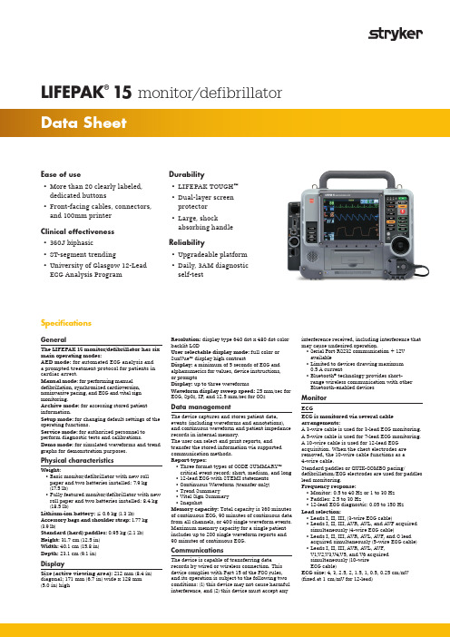
Ease of use• More than 20 clearly labeled, dedicated buttons • Front-facing cables, connectors, and 100mm printer Clinical effectiveness • 360J biphasic • ST-segment trending• University of Glasgow 12-Lead ECG Analysis ProgramLIFEPAK ®15 monitor/defibrillatorSpecificationsGeneralThe LIFEPAK 15 monitor/defibrillator has six main operating modes:AED mode: for automated ECG analysis and a prompted treatment protocol for patients in cardiac arrest.Manual mode: for performing manual defibrillation, synchronized cardioversion, noninvasive pacing, and ECG and vital sign monitoring.Archive mode: for accessing stored patient information.Setup mode: for changing default settings of the operating functions.Service mode: for authorized personnel to perform diagnostic tests and calibrations.Demo mode: for simulated waveforms and trend graphs for demonstration purposes.Physical characteristicsWeight: • B asic monitor/defibrillator with new roll paper and two batteries installed: 7.9 kg (17.5 lb)• F ully featured monitor/defibrillator with new roll paper and two batteries installed: 8.4 kg (18.5 lb)Lithium-ion battery: ≤ 0.6 kg (1.3 lb)Accessory bags and shoulder strap: 1.77 kg (3.9 lb)Standard (hard) paddles: 0.95 kg (2.1 lb)Height: 31.7 cm (12.5 in)Width: 40.1 cm (15.8 in)Depth: 23.1 cm (9.1 in)DisplaySize (active viewing area): 212 mm (8.4 in) diagonal; 171 mm (6.7 in) wide x 128 mm (5.0 in) highResolution: display type 640 dot x 480 dot color backlit LCDUser selectable display mode: full color or SunVue™ display high contrastDisplay: a minimum of 5 seconds of ECG and alphanumerics for values, device instructions, or promptsDisplay: up to three waveformsWaveform display sweep speed: 25 mm/sec for ECG, Sp02, IP, and 12.5 mm/sec for CO 2Data managementThe device captures and stores patient data, events (including waveforms and annotations), and continuous waveform and patient impedance records in internal memory.The user can select and print reports, and transfer the stored information via supported communication methods.Report types:• T hree format types of CODE SUMMARY™ critical event record: short, medium, and long • 12-lead ECG with STEMI statements • Continuous Waveform (transfer only)• Trend Summary • Vital Sign Summary • SnapshotMemory capacity: Total capacity is 360 minutes of continuous ECG, 90 minutes of continuous data from all channels, or 400 single waveform events.Maximum memory capacity for a single patient includes up to 200 single waveform reports and 90 minutes of continuous ECG.CommunicationsThe device is capable of transferring data records by wired or wireless connection. This device complies with Part 15 of the FCC rules, and its operation is subject to the following two conditions: (1) this device may not cause harmful interference, and (2) this device must accept anyinterference received, including interference that may cause undesired operation.• Serial Port RS232 communication + 12V available• Limited to devices drawing maximum 0.5 A current• Bluetooth ® technology provides short-range wireless communication with other Bluetooth-enabled devicesMonitorECGECG is monitored via several cable arrangements:A 3-wire cable is used for 3-lead ECG monitoring.A 5-wire cable is used for 7-lead ECG monitoring.A 10-wire cable is used for 12-lead ECG acquisition. When the chest electrodes are removed, the 10-wire cable functions as a 4-wire cable.Standard paddles or QUIK-COMBO pacing/defibrillation/ECG electrodes are used for paddles lead monitoring.Frequency response:• M onitor: 0.5 to 40 Hz or 1 to 30 Hz • P addles: 2.5 to 30 Hz • 12-lead ECG diagnostic: 0.05 to 150 Hz Lead selection:• Leads I, II, III, (3-wire ECG cable)• Leads I, II, III, AVR, AVL, and AVF acquired simultaneously (4-wire ECG cable)• Leads I, II, III, AVR, AVL, AVF, and C lead acquired simultaneously (5-wire ECG cable)• Leads I, II, III, AVR, AVL, AVF, V1,V2,V3,V4,V5, and V6 acquired simultaneously (10-wire ECG cable)ECG size: 4, 3, 2.5, 2, 1.5, 1, 0.5, 0.25 cm/mV (fixed at 1 cm/mV for 12-lead)Durability• LIFEPAK TOUGH™• Dual-layer screen protector • Large, shock absorbing handle Reliability• Upgradeable platform • Daily, 3AM diagnostic self-testLIFEPAK15 monitor/defibrillatorHeart rate display:• 20–300 bpm digital display• A ccuracy: ±4% or ±3 bpm, whichever is greater • Q RS Detection Range Duration: 40 to 120 msec • A mplitude: 0.5 to 5.0 mCommon mode rejection (CMRR): ECG Leads: 90 dB at 50/60 HzSp02/SpC0/SpMetSensors:• M ASIMO® sensors including RAINBOW®sensors• N ELLCOR® sensors when used with theMASIMO RED™ MNC adapterSp02Displayed saturation range: “<50” for levels below 50%; 50 to 100%Saturation accuracy: 70–100% (0–69% unspecified) Adults/pediatrics:±2 digits (during no motion conditions)±3 digits (during motion conditions)Dynamic signal strength bar graphPulse tone as Sp02 pulsations are detectedSp02 update averaging rate user selectable:4, 8, 12 or 16 secondsSp02 sensitivity user selectable: Normal, High Sp02 measurement: Functional Sp02 values are displayed and storedPulse rate range: 25 to 240 bpmPulse rate accuracy (adults/pediatrics):±3 digits (during no motion conditions)±5 digits (during motion conditions)Optional Sp02 waveform display withautogain controlSpC0®SpC0 concentration display range: 0 to 40% SpC0 accuracy: ±3 digitsSpMET®SpMet saturation range: 0 to 15.0%SpMet display resolution: 0.1% up to 10% SpMet accuracy: ±1 digitNIBPBlood pressure systolic pressure range: 30 to 255 mmHgDiastolic pressure range: 15 to 220 mmHg Mean arterial pressure range: 20 to 235 mmHg Units: mmHgBlood pressure accuracy: ±5 mmHgBlood pressure measurement time: 20 seconds, typical (excluding cuff inflation time)Pulse rate range: 30 to 240 pulses per minute Pulse rate accuracy: ±2 pulses per minute or±2%, whichever is greaterOperation features initial cuff pressure: User selectable, 80 to 180 mmHgAutomatic measurement time interval: User selectable, from 2 min to 60 minAutomatic cuff deflation excessive pressure:If cuff pressure exceeds 290 mmHgExcessive time: If measurement time exceeds 120 secondsCO2CO2 range: 0 to 99 mmHg (0 to 13.2 kPa)Units: mmHg, %, or kPaRespiration rate accuracy:• 0 to 70 bpm: ±1 bpm• 71 to 99 bpm: ±2 bpm Respiration rate range: 0 to 99 breaths/minuteRise time: 190 msecResponse time: 4.3 seconds (includes delay timeand rise time)Initialization time: 30 seconds (typical),10-180 secondsAmbient pressure: automatically compensatedinternallyOptional display: CO2 pressure waveform• S cale factors: Autoscale, 0–20 mmHg (0–4 Vol%),0–50 mmHg (0–7 Vol%), 0–100 mmHg (0–14 Vol%)Invasive pressureTransducer type: Strain-gauge resistive bridgeTransducer Sensitivity: 5µV/V/mmHgExcitation voltage: 5 VdcConnector: Electro Shield: CXS 3102A 14S-6SBandwidth: Digital filtered, DC to 30 Hz (< -3db)Zero drift: 1 mmHg/hr without transducer driftZero adjustment: ±150 mmHg includingtransducer offsetNumeric accuracy: ±1 mmHg or 2% of reading,whichever is greater, plus transducer errorPressure range: -30 to 300 mmHg, in six userselectable rangesInvasive pressure displayDisplay: IP waveform and numericsUnits: mmHgLabels: P1 or P2, ART, PA, CVP, ICP, LAP(user selectable)TemperatureRange: 24.8° to 45.2°C (76.6° to 113.4°F)Resolution: 0.1°CAccuracy: ±0.2°C including sensorReusable temperature cable: 5 foot or 10 footDisposable sensor types: Surface–Skin;Esophageal/RectalTrendTime scale: Auto, 30 minutes, 1, 2, 4, or 8 hoursDuration: Up to 8 hoursST segment: After initial 12-lead ECG analysis,automatically selects and trends ECG lead with thegreatest ST displacementDisplay choice of: HR, PR (SpO2), PR (NIBP),SpO2 (%), SpCO (%), SpMet (%), CO2 (EtCO2/FiCO2),RR (CO2), NIBP, IP1, IP2, STAlarmsQuick set: Activates alarms for all activevital signsVF/VT alarm: Activates continuous (CPSS)monitoring in Manual modeNo breath alarm: Occurs when 30 seconds haselapsed since last detected respirationHeart rate alarm limit range: Upper, 100–250bpm; lower, 30–150 bpmInterpretive algorithm12-Lead interpretive algorithm: University ofGlasgow 12-Lead ECG Analysis Program, includesAMI and STEMI statementsPrinterPrints continuous strip of the displayed patientinformation and reportsPaper size: 3.9 in (100 mm)Print speed: 25 mm/sec or 12.5 mm/sec• O ptional: 50 mm/sec time base for 12-leadECG reportsDelay: 8 secondsAutoprint: Waveform events print automaticallyFrequency response:• D iagnostic: 0.05 to 150 Hz or 0.05 to 40 Hz• M onitor: 0.67 to 40 Hz or 1 to 30 HzDefibrillatorBiphasic waveform: Biphasic TruncatedExponentialThe following specifications apply from 25 to200 ohms, unless otherwise specified:Energy accuracy: ±1 joule or 10% of setting,whichever is greater, into 50 ohms, ±2 joules or 15%of setting, whichever is greater, into 25-175 ohms.Voltage compensation: Active when disposabletherapy electrodes are attached. Energy outputwithin ±5% or ±1 joule, whichever is greater, of50 ohms value, limited to the available energywhich results in the delivery of 360 joules into50 ohms.Paddle options: QUIK-COMBO® pacing/defibrillation/ECG electrodes (standard). CableLength 8 foot long (2.4 m) QUIK-COMBO cable(not including electrode assembly).Standard paddles (optional)Manual modeE nergy select: 2, 3, 4, 5, 6, 7, 8, 9, 10, 15, 20, 30, 50,70, 100, 125, 150, 175, 200, 225, 250, 275, 300, 325,and 360 joulesCharge time: Charge time to 360 joules in lessthan 10 seconds, typicalSynchronous cardioversion: Energy transferbegins within 60 msec of the QRS peakPaddles leads off sensing: When usingQUIK-COMBO electrodes, the device indicatesPaddles Leads Off if the resistive part of the patientimpedance is greater than 300 ±15% ohms, or ifthe magnitude of the patient impedance is greaterthan 440 ±15% ohms.AED ModeShock Advisory System™ (SAS): an ECG analysissystem that advises the operator if the algorithmdetects a shockable or non-shockable ECG rhythm.SAS acquires ECG via therapy electrodes only.Shock ready time: Using a fully charged batteryat normal room temperature, the device is readyto shock within 20 seconds if the initial rhythmfinding is “SHOCK ADVISED”Biphasic output: Energy Shock levels rangingfrom 150–360 joules with same or greater energylevel for each successive shockcprMAX™ Technology: In AED mode, cprMAX™technology provides a method of maximizing theCPR time that a patient receives, with the overallgoal of improving the rate of survival of patientstreated with AEDs.Setup options:• A uto Analyze: Allows for auto analysis. Optionsare OFF, AFTER 1ST SHOCK• I nitial CPR: Allows the user to be prompted forCPR for a period of time prior to other activity.Options are OFF, ANALYZE FIRST, CPR FIRST• I nitial CPR Time: Time interval for Initial CPR.Options are 15, 30, 45, 60, 90, 120, and180 seconds.• P re-Shock CPR: Allows the user to be promptedfor CPR while the device is charging. Optionsare OFF, 15, 30 seconds.• P ulse Check: Allows the user to be promptedfor a pulse check at various times. Options areALWAYS, AFTER EVERY SECOND NSA, AFTEREVERY NSA, NEVERSpecifications cont.• S tacked Shocks: Allows for CPR after 3consecutive shocks or after a single shock.Options are OFF, ON• CPR Time: 1 or 2 User selectable times for CPR.Options are 15, 30, 45, 60, 90, 120, 180 seconds and 30 minutes.PacerPacing mode: Demand or non-demand rate and current defaultsPacing rate: 40 to 170 PPMRate accuracy: ±1.5% over entire rangeOutput waveform: Monophasic, truncated exponential current pulse (20 ± 1 ms)Output current: 0 to 200 mAPause: Pacing pulse frequency reduced by a factor of 4 when activatedRefractory period: 180 to 270 msec (functionof rate)EnvironmentalUnit meets functional requirements during exposure to the following environments unless otherwise stated.Operating temperature: 0° to 45°C (32° to 113°F); -20°C (-4°F) for 1 hour after storage at room temperature; 60°C (140°F) for 1 hour after storage at room temperatureStorage temperature: -20° to 65°C (-4° to 149°F) except therapy electrodes and batteriesRelative humidity, operating: 5 to 95%, non-condensing. NIBP: 15 to 95%, non-condensing Relative humidity, storage: 10 to 95%,non-condensingAtmospheric pressure, operating: -382 to4,572 m (-1,253 to 15,000 ft). NIBP: -152 to 3,048 m (-500 to 10,000 ft)Water resistance, operating: IP44 (dust and splash resistance) per IEC 529 and EN 1789 (without accessories except for 12-lead ECG cable, hard paddles, and battery pack)Vibration: MIL-STD-810E Method 514.4, Propeller Aircraft - category 4 (figure 514.4-7 spectrum a), Helicopter - category 6 (3.75 Grms), Ground Mobile - category 8 (3.14 Grms), EN 1789: Sinusoidal Sweep, 1 octave/min, 10-150 Hz, ±0.15 mm/2 g Shock (drop): 5 drops on each side from 18 inches onto a steel surface EN 1789: 30-inch drop onto each of 6 surfacesShock (functional): Meets IEC 60068-2-27 and MIL-STD-810E shock requirements 3 shocks per face at 40 g, 6 ms half-sine pulsesBump: 1000 bumps at 15 g with pulse duration of 6 msecImpact, non-operating: EN 60601-1 0.5 +0.05 joule impact UL 60601-1 6.78 Nm impactwith 2-inch diameter steel ball. Meets IEC62262 protection level IK 04.EMC: EN 60601-1-2:2006 Medical Equipment-General Requirements for Safety - Collateral Standard: Electromagnetic Compatibility - Requirements and Tests EN 60601-2-4:2003: (Clause 36) Particular Requirements for the Safety of Cardiac Defibrillators and Cardiac Defibrillator-MonitorsCleaning: Cleaning 20 times with the following: Quaternary ammonium, isopropyl alcohol, hydrogen peroxide Chemical resistance: 60 hour exposure to specified chemicals: Betadine (10% Povidone-Iodine solution), Coffee, Cola, Dextrose (5% Glucose solution), Electrode Gel/Paste (98% water, 2% Carbopol 940), HCL (0.5% solution, pH=1), Isopropyl Alcohol, NaCl solution (0.9% solution), Cosmetic discoloration of the paddle well shorting bar shall be allowed following exposure to HCL (0.5% solution).PowerPower adapters: AC or DCPower Adapters provide operation and battery charging from external AC or DC power• F ull functionality with or without batterieswhen connected to external AC/DC• T ypical battery charge time while installed inLIFEPAK 15 device is 190 minutes• I ndicators: external power indicator, batterycharging indicatorDual battery: Capability with automatic switching Low battery indication and message: Low battery fuel gauge indication and low battery message in status area for each batteryReplace battery indication and message: Replace battery fuel gauge indication, audio tones and replace battery message in the status area for each battery. When replace battery is indicated, device auto-switches to second battery. When both batteries reach replace battery condition, a voice prompt instructs user to replace battery.Battery capacityFor two, new fully-charged batteries, 68°F (20°C)OperatingmodeMonitoring(minutes)Pacing(minutes)Defibrillation(360J discharges) Totalcapacityto shutdownTypical360340420Minimum340320400Capacityafter lowbatteryTypical212030Minimum12106 BatteryBattery specificationsBattery type: Lithium-ionWeight: ≤1.3 lb (0.6 kg)Charge time (with fully depleted battery):< 190 minutes (typical)Battery indicators: Each battery has a fuel gauge that indicates its approximate charge. A fuel gauge that shows two or fewer LEDs after a charge cycle indicates that the battery should be replaced. Charging temperature range: 5° to 45°C(41° to 113°F)Operating temperature range: 0° to 45°C (32° to 113°F)Short term (<1 week) storage temperature range: -20° to 60°C (-4° to 140°F)Long term (>1 week) storage temperature range: 20° to 25°C (68° to 77°F)Operating and storage humidity range:5 to 95% relative humidity, non-condensingEmergency CareThis document is intended solely for the use of healthcare professionals. A healthcare professional must always rely on his or her own professional clinical judgment when deciding whether to use a particular product when treating a particular patient. Stryker does not dispense medical advice and recommends that healthcare professionals be trained in the use of any particular product before using it.The information presented is intended to demonstrate Stryker’s product offerings. A healthcare professional must always refer to operating instructions for complete directions for use indications, contraindications, warnings, cautions, and potential adverse events, before using any of Stryker’s products. Products may not be available in all markets because product availability is subject to the regulatory and/or medical practices in individual markets. Please contact your representative if you have questions about the availability of Stryker’s products in your area. Specifications subject to change without notice.Stryker or its affiliated entities own, use, or have applied for the following trademarks or service marks: CODE SUMMARY, LIFEPAK, LIFEPAK TOUGH, QUIK-COMBO, SpC0, SpMET, Stryker. Masimo, the Radical logo, Rainbow and SET are registered trademarks of Masimo Corporation. All other trademarks are trademarks of their respective owners or holders.The absence of a product, feature, or service name, or logo from this list does not constitute a waiver of Stryker’s trademark or other intellectual property rights concerning that name or logo.GDR 3341463_ACopyright © 2019 Stryker Manufactured by:Physio-Control, Inc.11811 Willows Road NERedmond, WA, 98052 U.S.A.Toll free 800 442 1142Stryker EuropeanOperations B.V.Herikerbergweg 1101101 CM AmsterdamNetherlandsfor Physio-Control, Inc.Tel +31 (0)43 3620008Fax +31 (0)43 3632001Distributed by:Stryker UK LtdStryker HouseHambridge RoadNewbury, BerkshireRG14 5AWUnited KingdomDistributed by:Stryker Australia Pty Ltd8 Herbert StreetSt Leonards NSW 2065AustraliaToll Free Tel 1800 987 982Toll Free Fax 1800 890 892For further information, please contact your Stryker representative or visit our website at 。
- 1、下载文档前请自行甄别文档内容的完整性,平台不提供额外的编辑、内容补充、找答案等附加服务。
- 2、"仅部分预览"的文档,不可在线预览部分如存在完整性等问题,可反馈申请退款(可完整预览的文档不适用该条件!)。
- 3、如文档侵犯您的权益,请联系客服反馈,我们会尽快为您处理(人工客服工作时间:9:00-18:30)。
International Journal of Technology Management1 IntroductionEnvironmental art design is a blend of art, architecture, landscape, cultural environment, construction and other fields furnishings comprehensive discipline, but also a highly practical disciplines. At present, many domestic colleges and universities are now offering this course in environmental design practice teaching model also carried out a series of reforms and explore. However, most open environment design professional institutions reform effect is not ideal, the reason is not fully based on reality, built up in favor of the application of talent, more reasonable teaching system, not based on environmental art and design education its own characteristics and the actual needs of the market to develop design talent.Industry trends determine the change in professional colleges and universities teaching mode, environmental design because in recent years in the construction industry, driven, formed a good momentum of development. Therefore, for people entering the industry, environmental design requirements are also increasing, which is mainly reflected in the practice experience. A good designer should not only have profound theoretical knowledge, but also in the signing of the contract, terms of project design, budget and fi nal accounts, construction supervision has a wealth of experience, which requires environmental design major in the teaching process to strengthen the sense of practice teaching.Students are the main environmental design teaching and teachers should subtly guide and inspire students to practice awareness in the teaching process. American educator said: “Just tell students scientific concepts and principle is not efficient.” The study also found that psychological experts, a specifi c scene teaching will increase the enthusiasm of students, the students are familiar with the theory of teaching arrangements in environment which performed so that students can consciously into teaching activities. The door to the ergonomic theory class, for example, teachers in the basic course on to explain, at fi rst, the students set specifi c measurement tasks, then let the students come out from the classroom to the bedroom, dining room, library and so they familiar environment to go to space and materials to conduct site surveys, measurements data is completed, the actual measurement of aggregated. Finally, the size of the control data and indicators provided in ergonomics, and found differences textbook summary of data and the actual space and the size of the object, so that students in the process of teaching theory course through hands-on experience, more deeply grasp textbook knowledge and understanding of real life items placed in different places on the size requirements of the similarities and differences, for the latter case design courses lay a good foundation. Finally realize that the relationship between theory and practice, and to enhance students’ awareness of the practice, so that students in the future be able to take the initiative to put into practice activities to consolidate the theoretical knowledge and theoretical knowledge into practice.Environmental design teaching process focusing on specifi c aspects of teaching practice, requires colleges and universities to further improve the construction of practice base, make the environment design students at the school can accept standard industry training, shorten the adaptation period of graduates entering the workplace, thereby improving environmental designstudents’ employment success rate.Figure.1 Environmental design2 The Proposed Methodology2.1 Based on workshop mode of operationWorkshop mobility is stronger joint working mode and in order to discuss the entire process quickly and find the most suitable site solution we must do a lot of butt in the early stage of coordination work. On the exhibition front, the more the level of the communication to solve problems, practice the process of resistance will be smaller.Art and design education with emphasis on cultivating innovation and creativity of students emotional level ofI nnovation of “Workshop” Mode in Modern PracticeTeaching of Environmental Design MajorFang Tu( Wuhan Donghu University,Wuhan, Hubei Province,430212 China )Abstract. In recent years, colleges and universities of the international cooperation and increase exchange opportunities, new forms of teaching cooperation: Joint workshop interscholastic consequent, is a good way to promote art and design professional domestic and international exchanges. Workshop practice teaching model is increasingly being taken seriously in college teaching design, the paper analyzes the school of design Workshop’s fi rst teaching mode, status of development and systematic investigation of University teaching studio at home and abroad into the details of the Workshop teaching mode in design majors unique advantages, a number of recommendations to build Workshop practice teaching model, in order to improve the artistic design students innovative ability.Keywords: workshop, education, environmental design, professional practice teaching, innovative research.— 69 —Conference Proceedings Citation Indexconsciousness, a strong personality and art students of divergent thinking has certain advantages, but also lead to further academic rigor is not enough, the design works great there is lack of design elements stacked and sense of space extent. So whether it is the school practice or with the outside joint teaching, curriculum teachers and students have to practice the subject of pre-collection, research, discussion, docking and the need to use design software to simulate the scene a sense of space, some consensus in the initial communication. This process enhances the systematic and rigorous practice of teaching and consistent throughout the teaching process, reinforce the spirit of seeking truth and art and design professional teachers.2.2 Workshop backgroundTeaching model Workshop or activity that is the camp for a long time, the earliest dating back to the establishment of the German Bauhaus School of Design in the early 20th century as the 1919 Walter Gropius advocated “art and technology”, “teaching and practice,” a combination of the education system, the “dual system” of teaching, each course by an “art teacher” (form teacher) and a “technology teachers” (studio teacher) together professors, students also received a double education of art and technology. Bauhaus workshops teaching form is actually today’s studio in the form of prototype, it is a completely open, some basic characteristics with enterprise features and design companies.European and American design artistic level has been a world leader, thanks Workshop practice teaching. This form is not only present in the university’s teaching, but also in primary and secondary education, and has become a key Western countries to improve the quality of teaching to inspire students to think independently, cultivate innovation.2.3 Workshop practice teaching mode connotation and featuresWorkshop is hosted by one or several with expertise in a certain fi eld as the core, by the research team of about 10 people at the moderator’s guide for topics to explore research by organizing various activities. Workshop in a foreign country is known as the “creative Workshop”, that is the way multilateral cooperation projects, which vary in size, is used for more intensive stage of the project, and its essence is to use peer pressure and effective guidance to complete some complex and challenging work. Workshop practice teaching model is a comprehensive practice teaching mode, teaching mode is a profession of teaching theory and practice of combining.Workshop practice subject teaching mode of students to train instead of imparting knowledge and abilities in a panel discussion instead of class teaching system and it emphasizes student-centered, teacher guide, student respect and trust of students, for students to be fully developed personality. In the process of teaching exchange, teachers do not give students answers to questions or provide information, but to teach students how to explore the answer to that question, and promote independent learning, through summary evaluation to measure learning outcomes.Workshop teaching model emphasizes learning by doing, training and exercise capacity in practice, through market research, internal and external teaching base practice, social practice and other activities for students out of the textbook, out of the classroom, prompting students to indirect books, system professional knowledge and expand the rapid conversion, which is applied to practical work to enable students to truly step into the actual design phase.Workshop practice teaching mode of teaching respect for the art and design their own special and creative law, a blend of classroom instruction, contests, projects, practices; strengthen the process of teaching, practice teaching, study and research to create a good atmosphere for students with limited innovation culture within the comprehensive capability. It broke the previous traditional teaching mode, the passive acceptance of knowledge into the students active learning, art and design teaching in a very meaningful practice teaching.2.4 Construction Workshop Practice Teaching ModeReform of curriculum, workshop in art and design practice teaching mode, the system is very important to establish a good course. Art and Design is the fundamental goal of professional training courses based system to adjust the capacity necessary for the professional training of decomposition, matching courses and systematize, and establish a modern management education as the guide and many courses were integrated curriculum system. Course Group clearly the respective center of gravity and interrelated, highlight Main Courses, close convergence at all stages and at all levels of the curriculum, as well as contact with the vertical and horizontal curriculum subjects. At the same time, according to the capacity-building to develop a reasonable scientific syllabus, highlighting the theme of the design, the students focus on the overall design thinking to guide and inspire. We need to learn cognitive law gradual completion of the task of teaching, building the foundation to expand the group courses, professional courses group focused practice courses and professional quality of internal and external education programs covering multi-dimensional, three-dimensional curriculum, enable students to master basic At the same time a comprehensive theoretical knowledge of professional practice to master skills and achieve sustainable development of art and design education.2.5 Extended research practice baseArt and design courses are mainly practical courses. Workshop to promote the implementation of practical teaching mode requires multi-level research practice base for students to practice the project, in order to truly implement the teaching practice. We should actively expand research practice base, innovation and research exchange platform, technology, knowledge, talent, information and other resources to the mutual flow. This discipline construction played a direct guiding and promoting the role of students in professional quality of training and training in the real business environment, the ability to expertise courses to learn skills and the actual design combine to enhance students’ practical ability, achieve direct contact with the market, and positions during practice and expand their horizons, to lay a broader foundation for future employment.Perfecting Teaching Management Mechanism. Changes in teaching mode will inevitably lead to changes in management, teaching evaluation and so on, so we need to establish a comprehensive and integrated management of the agency.— 70 —International Journal of Technology ManagementWorkshop teaching activities carried out in the beginning, teachers and workshop instructors teaching must develop a detailed deployment, detailed teaching mission and objectives, methods, themes, organization and other programs and submitted College teaching management mechanism for review to protect the daily teaching and independent studio running smoothly and achieved good teaching results when the development of teaching teachers should grasp the deployment of dynamic design, pay attention to the integration of new knowledge, new technology, new areas, new problems in the course.2.6 Innovation Workshop evaluation systemExamination evaluation system of art design course is to achieve effective support for personnel training objectives. Based on the analysis of art design teaching and assessment on the status of the problem, focus on training objects necessary knowledge, ability and quality structure required to build fl exible assessment methods, assessment comprehensive and scientific evaluation criteria diversifi ed art course evaluation system.2.7 Current Environmental Art College Teaching and Development ProblemsCurrently, due to environmental art and design in China is still an emerging discipline, the relative lack of experience in teaching, teaching system is still not perfect. Especially in the mode of living design education, there are still many problems in terms of how to foster innovative and application-oriented talents.First, because of the control mechanism for the appointment of universities, environmental design professional teachers mainly from related institutions graduate design professionals. Although most of these teachers are more abundant theoretical knowledge, artistic accomplishment is higher. But after entering the system of colleges and universities, teaching is mostly arduous task, not too much time and energy into practice projects. Over time, teachers themselves can easily be separated from social practice, some of the latest and most cutting-edge design concepts and knowledge decorative materials and process technologies are not updated knowledge and practical needs of the community classroom granted a far cry from the situation often appears on paper.Secondly, the traditional teaching mode usually pay attention to the system of teaching theory, ignoring the principle of renewal and development of the theory of the times match. Students are often limited to the classroom. Of course, for schools, classroom teaching really easy assessment and management, but they ignore environmental design disciplines such strong features of its own practice. This mechanical teaching model is likely to cause teachers scripted, students passive learning situation.2.8 Reform practice of innovative teaching modeFirst, we should establish a mechanism for training teachers to encourage teachers to teach in the post apart, rotation learning training, which is not necessarily confined to colleges and universities, teachers should use its own resources, to participate in social practice project. Department can arrange courses, regularly organized teams of teachers out inspection training, teacher training after professional teaching in this report learning experience, to carry out academic exchanges between teachers, teachers to maximize learning, but also conducive to mutual teaching team learn from each other as teachers in the teaching part of the professional practice courses, according to the characteristics and requirements of the curriculum, class time and in the form of job completion and assessment criteria, to take a variety of specifi cations and methods. This fl exible and open form of teaching is actually more conducive to grasp the knowledge students multiple professional disciplines.Environmental art design professional teaching practice should be based on reality, the development of keeping with the times. Only continue to improve their teaching ideas to improve the quality of teaching, in order to cultivate the ability of both innovation and practical ability has excellent design talent3 ConclusionWorkshop is based on exchange, interaction, new research practice teaching mode as the main form, which is the current art and design education tend talents training model innovation is consistent. The development of innovative education, and social standards and international standards, we must build a scientific and rational curriculum, supporting the practice platform, the workshop practice teaching track parallel in art and design education, so that students will course learn professional knowledge, skills and market application of combining the quality of vocational training and training in practice to achieve during the learning market, direct contact with the post, and then train students’ innovation, entrepreneurship, and ultimately achieve the ultimate goal of design education.Reference1. Geist, Valerius. Life strategies, human evolution, environmental design: toward a biological theory of health. Springer Science & Business Media, 2013.2. Marans, Robert W., and Daniel Stokols, eds. Environmental simulation: Research and policy issues. Springer Science & Business Media, 2013.3. Ekblom, Paul, et al. “Crime prevention through environmental design in the United Arab Emirates: a suitable case for reorientation?.” Built Environment 39.1 (2013): 92-113.4. Reniers, Genserik LL, and Amaryllis Audenaert. “Preparing for major terrorist attacks against chemical clusters: Intelligently planning protection measures wrt domino effects.” Process Safety and Environmental Protection 92.6 (2014): 583-589.5. Azari, Rahman. “Integrated energy and environmental life cycle assessment of office building envelopes.” Energy and Buildings 82 (2014): 156-162.6. Hyde, Richard. Climate responsive design: A study of buildings in moderate and hot humid climates. Taylor & Francis, 2013.— 71 —。